Page is loading ...

IA06 Data Sheet (NZ326) Page 1Texmate, Inc. Tel. (760) 598-9899 • www.texmate.com
Interface to Texmate's full
range of modular panel
meters.
Hardware Module Specifications
Fits Lynx, Leopard & Tiger 320 Series
AC VOLTS TRUE RMS 200/600 V
HIGH
ACCURACY
LOAD-CELL
PRESSURE
PROCESS
4 / 20 mA
1 / 5 V
VOLTS
AC / DC
AMPS
AC / DC
WATTS
AC / DC
FREQUENCY
RPM, Pulse, Counter
TEMPERATURE
T/C, RTD
RESISTANCE
INPUTS
Span Potentiometer.
Fine full scale adjustment.
Voltage Input.
Header.
Selectable 200 V or 600 V
input range.
State-of-the-Art
Electromagnetic Noise Suppression.
Circuitry ensures signal integrity
even in harsh EMC environments.
Voltage Range 200 V or 600 V RMS, header selectable 0.02 % linearity
over full scale.
Frequency Range 0 to 6 KHz, independent of input voltage.
Resolution 1 mV RMS over full scale input.
Accuracy
Lynx 0.05% of full scale input ± 2 digit.
Leopard 0.05% of full scale input ± 2 digit.
Tiger 0.05% of full scale input ± 1 digit.
Output Signal Adjustable about 2 V dc for 200 V RMS full scale
using SPAN potentiometer.
Span Drift ± 50 ppm/°C of full scale maximum.
Meter Interface Can be utilized in the full Texmate range of modular
Lynx indicators, Leopard meter relays, and Tiger controllers.
Some Relevant Operating System Features
Direct display of true RMS voltage.
Setpoint control (Tiger & Leopard).
Full scale calibration accurate for any sized signal.
Texmate Proprietary Designed
RMS-to-DC Convertor.
High accuracy, extremely linear.
Differential Voltage Divider.
Safe operation for connection to
high voltages.
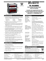
The IA06 true RMS input module provides unprecedented linearity over a choice of 200 or 600 volt RMS
ranges utilizing the Texmate designed ∆∑ RMS-to-DC convertor circuit block. True differential input and
high input impedance 2MΩ improved RFI/EMI rejection and protection at high input voltages. High
linearity means simple system calibration.
True RMS voltage measurements for the AC power industry.
IA06
Input Module
Order Code Suffix

Texmate, Inc. Tel. (760) 598-9899 • www.texmate.comPage 2 IA06 Data Sheet (NZ326)
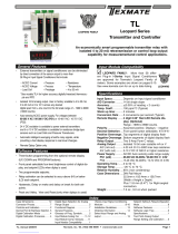
Connector Pinouts
Description
300C
INPUT
Volts RMS
GND
PIN 1
PIN 2
PIN 3
IA06 wired to monitor RMS volts on 200 V full scale
The AC volts true RMS input module is a universal module designed to function with the Lynx, Leopard, and Tiger range of indicators,
meter relays, and programmable meter controllers (PMCs). Commonly used in the 0 to 200 V range, a 0 to 200/600 V range header
provides the option to go to a higher v oltage.
The IA06 has a diff erential input with common mode filter ing and a v oltage divider to atten uate the high input v oltage to safe levels.
Zero input voltage produces a 0 output signal, meaning no z ero adjustment is necessary.
Tiger Controllers and Leopard Meter Relays
The Tiger and Leopard r ange use inter nal software functions to calibr ate the span. However, it may be necessar y to adjust the sp an
potentiometer to bring the maximum input signal within the full scale r ange of the instrument.
Turn span pot counter- clockwise
to decrease reading
300C
When the input signal is be yond the
full scale r ange of a Tiger controller,
the display flashes [OVER]. When the
input signal is be yond the full scale
range of a Leopard meter , the top
segment of each digit of the displa y
flashes.
Figure 2 – Span Potentiometer Adjustment
Lynx Indicators
The span potentiometer is the only means of calibr ating Lynx
indicators. When the input signal is beyond the full scale range
of a Lynx indicator, a 1 is displayed in the most significant digit
(MSD) with all other digits b lank. Turn the 15 tur n span poten-
tiometer counter-clockwise to decrease the signal until a read-
ing appears on the display (See Figure 2).
SPAN Turn clockwise to
increase reading
Viewed from
the right-hand
rear of meter
Span Potentiometer (Pot)
The 15 tur n span potentiometer is located on the r ight-hand
side of the input module (when vie wed from the rear of the
meter). Typical adjustment is 20% of the input signal r ange
(See Figure 3).
Figure 3 – Span Pot
Turn the 15 tur n span potentiometer
counter-clockwise to decrease the
signal until a reading appears on the
display (See Figure 2). Now calibrate
the instr ument using the softw are
calibration method f or y our instr u-
ment.
Figure 1 – IA06 Input Module Component La yout
WARRANTY
Texmate warrants that its products are free from def ects in mater ial and w orkmanship under
normal use and ser vice for a per iod of one y ear from date of shipment. Texmate’s obligations
under this warranty are limited to replacement or repair, at its option, at its factory, of any of the
products which shall, within the applicable period after shipment, be returned to Texmate’s facil-
ity, tr ansportation charges pre-paid, and which are , after e xamination, disclosed to the satis-
faction of Texmate to be thus def ective. The warranty shall not apply to an y equipment which
shall have been repaired or altered, except by Texmate, or which shall have been subjected to
misuse, negligence , or accident. In no case shall Texmate’s liability e xceed the or iginal pur-
chase price. The aforementioned provisions do not e xtend the original warranty period of an y
product which has been either repaired or replaced b y Texmate.
USER’S RESPONSIBILITY
We are pleased to offer suggestions on the use of our v arious products either by way of print-
ed matter or through direct contact with our sales/application engineering staff. However, since
we ha ve no control o ver the use of our products once the y are shipped, NO WARRANTY
WHETHER OF MERCHANT ABILITY, FITNESS FOR PURPOSE, OR O THERWISE is made
beyond the repair, replacement, or refund of purchase pr ice at the sole discretion of Texmate.
Users shall deter mine the suitability of the product f or the intended application bef ore using,
and the users assume all risk and liability whatsoever in connection therewith, regardless of any
of our suggestions or statements as to application or constr uction. In no event shall Texmate’s
liability, in law or otherwise, be in excess of the purchase pr ice of the product.
Texmate cannot assume responsibility for any circuitry described. No circuit patent or software
licenses are implied. Texmate reserves the right to change circuitry, operating software, speci-
fications, and prices without notice at any time.
Tel: 1-760-598-9899 • USA 1-800-839-6283 • That’s 1-800-TEXMATE
1934 Kellogg Ave. • Carlsbad, CA 92008
Fax: 1-760-598-9828 • Email: [email protected] • Web: www.texmate.com
/