Page is loading ...

Issue 1.13
Caresse and Caresse+
Installation and
programming guide

Page 2 of 40
Contents
What’s in the box? ........................................................................................................3
The Caresse...................................................................................................................4
For your safety - installation advice.............................................................................5
How to install the Caresse............................................................................................6
Using the Caresse .........................................................................................................8
Making an alarm call ...............................................................................................................8
Cancelling an alarm call ..........................................................................................................8
Answering calls remotely via the pendant ................................................................................8
Status warnings.............................................................................................................9
Telephone line monitoring .......................................................................................................9
AC Power failure monitoring....................................................................................................9
The LEDs on the Caresse indicate ........................................................................................10
The LED on the pendant indicates.........................................................................................10
Battery information .....................................................................................................11
Caresse ................................................................................................................................11
Replacing the Caresse battery........................................................................................................ 11
Pendant ................................................................................................................................ 11
Programming the Caresse..........................................................................................12
Programming keypad ............................................................................................................12
Frequently used keypad codes.............................................................................................. 13
Locking/Unlocking the keypad ........................................................................................................ 13
Resetting the Caresse.................................................................................................................... 13
Setting the time.............................................................................................................................. 13
Setting the date.............................................................................................................................. 13
Adjusting the speaker volume......................................................................................................... 14
No fault report window.................................................................................................................... 14
Language selection........................................................................................................................ 14
Alarm numbers......................................................................................................................15
Call sequences .....................................................................................................................18
Unit ID number...................................................................................................................... 19
Pendants and telecare sensors .............................................................................................20
Turning features on and off....................................................................................................21
Features list................................................................................................................................... 22
Features explained and configuring settings..........................................................................23
Periodic test calls........................................................................................................................... 23
Away button................................................................................................................................... 23
Inactivity monitoring ....................................................................................................................... 24
Intruder monitoring (Caresse+ only)................................................................................................ 25
Reminder functionality (Caresse+ only)........................................................................................... 26
Critical visits (Caresse+ only) ......................................................................................................... 29
Personal recipient messages.......................................................................................................... 30
Hard wired input/output connection................................................................................................. 30
Contact ID protocol compatibility ..............................................................................31
Contact ID call codes ............................................................................................................32
Operator instructions for controlling speech during a Contact ID call. .....................................32
Contact ID Mode Call Handling Functionality (listen in mode) ................................................33
Contact ID Mode Call Handling Functionality (Call Back mode) .............................................34
List of Contact ID Call codes for Caresse and Caresse +.......................................................35
TT21 Location codes and descriptions......................................................................38
Technical Details.........................................................................................................39
Environmental.......................................................................................................................39
Standards ............................................................................................................................. 39

Page 3 of 40
What’s in the box?
When the box is opened for the first time, please ensure it includes all of the following:
Caresse
Pendants
Gem+ OR Amie+
Wearing options
Gem+ Amie+
Cords and adaptors
ⓐ Telephone cord (10’ (3m) cable)
ⓑ AC power adaptor (10’ (3m) cable)
Installation and User Guide
If any of the above items are missing, please contact your supplier.
Wrist strap
Wrist strap
Neck cord
Neck cord
Belt clip

Page 4 of 40
The Caresse
Front view
Back view
End view
AUX
–
Accessory Jack
AC
–
Power Adaptor Jack
℡
-
Telephone Jack
LINE
–
Telephone Cord Jack
Aerial
Status LED (Red/Yellow)
Status LED (Green)
Cancel Button (Green
)
Away Button
(
Blue
)
Speaker
Alarm Button (Red)
Microphone
Battery
Compartment
Cover
Wall Mounting Points
Programming Keypad
Rubber Feet x 4

Page 5 of 40
For your safety - installation advice
Installation with RJ31x (CA38A in Canada)
The Caresse unit must be able to seize the telephone line and place a call in an
emergency situation. It must be able to do this even if other equipment (telephone,
answering system, computer modem, etc.) already has the telephone line in use. To do
so, the Caresse must be connected to a properly installed RJ31x jack that is electrically
in series with and ahead of all other equipment attached to the same telephone line.
Installation without RJ31x (CA38A in Canada)
Connect the Caresse to the first telephone jack in the
dwelling with all other telephones/extension phones/smart
boxes/modems/TV set top boxes in the home plugged
directly into the Caresse using the jack on the Caresse
labeled ℡ to enable the unit to disconnect extension
telephones when raising an alarm call. A multiple
telephone adaptor may be required to connect more than
one telephone (not supplied).
Cordless phones
Ensure that the main base/charger which is registered to all other handsets in use is
connected directly to the Caresse as above.
Broadband
Please ensure a high quality ADSL filter is in use and the Caresse is connected to the
phone (analogue) socket on the filter. Please contact your supplier for further advice if
necessary.

Page 6 of 40
How to install the Caresse
Dos
• Keep the Caresse connected to the AC power at all times.
• Use an RJ31x jack or connect the Caresse to the first telephone point in the
dwelling with all other extensions wired into the unit to ensure proper operation
even when another telephone is in use or off hook.
Don’ts
• Expose the Caresse to water or other liquids.
• Connect cables other than those supplied with the unit.
• Place your Caresse next to something that makes a lot of noise, such as next to
a television, radio or washing machine.
• Put it right next to your stove or close to any other heat source.
• Set the Caresse in a place where it will get damp, such as a bathroom, or near
house plants that are sprayed at any time.
• Place it very close to any large metal objects, such as microwave ovens, as large
pieces of metal stop the signals from the radio pendant reaching the Caresse.
• Place your Caresse closer than four feet to something that may emit
electromagnetic interference, such as a cordless telephone, CD or video player,
or personal computer.
Step 1 - Connecting the leads and adaptors
Please follow the steps below to plug the cords correctly into the Caresse.
Step A – Plug the telephone cord ⓐ into the
jack on the Caresse labeled LINE and the
first/main telephone wall jack.
Step B – Plug the telephone into the jack on
the Caresse labeled ℡. Plug all required
telephones / equipment into this jack using a
multi socket extension if required (not
supplied). See page 5 for more details.

Page 7 of 40
Step C – Plug the AC adaptor ⓑ into the jack
on the Caresse labeled AC and then connect to
the power receptacle.
Step D – Adjust speaker volume if required
(see page 14 for more details).
Step E – Stand the aerial upright.
Step 2 - Testing
Press the red alarm button on the Caresse and ensure it raises a call through to the
monitoring center/personal recipient. Also remember to test the Amie+ or Gem+ pendant
by pressing its red button and ensuring a call is raised. Do this test at floor level around
the dwelling to confirm the dwelling is covered.
Step 4 – Adding pendants or telecare sensors
For more information on adding pendants and telecare sensors, please see page 21 of
this guide.
Step 5 – Ready to use
Once successfully tested, the Caresse is ready for use.
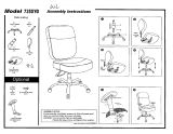
Wall mounting
Decide where you want to situate the Caresse. Remember it should be within 2 meters
of the AC power and main telephone line socket. Then drill 2 holes 149mm apart, firmly
attach screws and then locate the wall mounting points on the Caresse with the screws.
NOTE: The diagram above is for illustrative purposes only and should not be used as a measuring tool i.e. it
is not drawn to scale.
149mm

Page 8 of 40
Using the Caresse
Making an alarm call
Press the red button on pendant or red alarm button on the Caresse.
Cancelling an alarm call
If you raise an alarm call by accident, wait 5 seconds (after the initial alarm button is
pressed) and press the green cancel key. This in-built delay prevents false cancellation
of an alarm call. Alarm calls made from a pendant can be cancelled immediately by
pressing the green cancel key.
Answering calls remotely via the pendant
The Amie+ or Gem+ pendant can be used to answer incoming telephone calls remotely
by pressing its red button while the Caresse or connected telephone is ringing. When
pressed, the Caresse will answer the call and you can speak to and hear the caller
hands free via the Caresse. To revert to handset mode, just pick up the handset of the
connected telephone. Replacing the handset will end the call. To end a hands free call,
press the pendant again.

Page 9 of 40
Status warnings
Telephone line monitoring
If the telephone line is faulty or becomes disconnected, the Caresse will announce
‘WARNING – the telephone line is disconnected’ after 1 minute. This warning will be
repeated every 30 seconds until the telephone line becomes available again.
To silence the warning, re-connect the telephone line. If the telephone line is connected
and the warning continues, press the green cancel key. If the warning continues you
should contact your telephone line supplier as the telephone line may be faulty.
AC Power failure monitoring
If an AC power failure occurs, the Caresse will continue to work using its backup battery,
however, as a warning the green LED will flash once every 4 seconds (see section – the
LEDs on the Caresse indicate). The unit will also announce ‘WARNING – there is no
electrical power’. This warning is repeated every 5 minutes. To silence the warning
reconnect the power cord, or press the green cancel key.
If the power failure lasts for more than 1 hour, during the next hour the unit will
automatically call the monitoring center. A call will then be raised periodically to the
monitoring center until the power is restored. The battery provides 30 hours backup.

Page 10 of 40
The LEDs on the Caresse indicate
Two LEDs on the Caresse provide indications of its status based on the below.
LED lights Home unit status
Green LED on Normal mode
Green LED flash (1 every 4
seconds)
Normal mode running on battery
(mains power off)
Green LED flash (1 every second) Alarm mode
Red LED flash (2 every second) Telephone line disconnected
Red LED on Telephone line in use
Yellow LED on Away button in away mode
Yellow LED off Away button in home mode
Yellow LED flash (2 every second) Intruder entry/exit time period
No LED on
Unit powered down (if power is on
and connected then the unit may be
faulty)
The LED on the pendant indicates
When pressed the red LED on the Amie+ or Gem+ pendant will light up. This is to
indicate that the button has been pressed. If the LED flashes when pressed this
indicates that the pendant battery is low and should be replaced.

Page 11 of 40
Battery information
Caresse
The Caresse contains a Nickel Metal Hydride back-up battery that is user replaceable
and recharges itself when plugged into the AC power. It is recommended that this
battery is replaced after 5 years. The battery provides 30 hours of standby operation (15
hours with one 30 minute alarm call). The battery in the Caresse can be tested by
pressing the TEST button on the programming keypad (3 bleeps = battery ok, 1 long
bleep = fail).
NOTE: If 1 bleep is heard ensure the battery is installed correctly and has been charged for at least 24 hours
then retest. If 1 bleep is heard again the battery should be replaced. A test should be carried out each time a
battery is fitted.
Replacing the Caresse battery
CAUTION! There may be a risk of explosion if the battery is replaced by an incorrect type. Dispose of used
battery in accordance with the latest legislation.
Remove the battery cover and old battery Connect the new battery cords
Insert the new battery Replace the battery compartment cover
Pendant
The Amie+ or Gem+ contains a 3V Lithium battery that is not user replaceable. The
battery has an expected life of 5 years (20,000 operations). All batteries should be
disposed of in accordance with the latest legislation.

Page 12 of 40
Programming the Caresse
Programming of the Caresse and its functions can be achieved using three different
methods:
• Programming Keypad - Basic programming can be achieved by using the
programming keypad on the underside of the Caresse. This includes a simplified
way of programming telephone numbers, call codes and the turning on/off of
functions of the Caresse. Instructions are included within this programming guide.
• Tunstall PNC4 and CMS 4000 – this method allows more in depth remote
programming at the monitoring center using custom designed screens within the
PNC software (depending upon the software version) or via manual entry of
parameters.
• PC Connect Programming Tool - Full programming can be achieved using the
PC Connect programming tool on a PC linked to the Caresse.
Programming keypad
All programming begins and ends with
except for programming of the test alarm to
the monitoring center.
Each time a key is pressed a tone is
sounded indicating that the press is
approved. After each programming
sequence a tone is sounded indicating the
following:
Successful programming = 3 tones
Unsuccessful programming = 1 tone
Explanation
In the following instructions the below keys have the following meanings:
This button press can be 1, 2, 3 or 4 depending upon the position of the
number required to program. For example to program monitoring center
number 2, press 2 when this key is shown.
Monitoring center number 1 (2, 3 and 4 also used)
Personal Recipient number 1 (2 and 3 also used)
Information monitoring center number 1 (2 also used)
NOTE: All programming not listed in this guide must be completed using the PC Connect programming tool
or via the monitoring center.

Page 13 of 40
Frequently used keypad codes
Locking/Unlocking the keypad
To prevent buttons from being pressed accidentally, the keypad can be locked/unlocked.
Each time the Caresse is programmed, the keypad should be unlocked then locked
again after the programming is completed.
To unlock, press:
To lock, press:
Resetting the Caresse
To reset all previous programmed information press:
Resetting erases all programmed telecare sensors and triggers and all functions are
reset to default settings. The date and time will also need to be reset.
Setting the time
There is a real time 24 hour clock in the Caresse which automatically adjusts to Daylight
Saving Time. To set the clock press:
HH MM
HH represents hours 00-23; 24 cannot be programmed
MM represents minutes 00-59; 60 cannot be programmed
NOTE: The automatic Daylight Saving Time update can only be disabled via the PC Connect programming
tool or the monitoring centre.
Setting the date
DDMMYYYY

Page 14 of 40
Adjusting the speaker volume
The Caresse has four volume level settings, which can be adjusted as follows.
To increase volume, press:
Tone sounds for 10 seconds. Press repeatedly until volume is reached.
Then press
before the tone ends to save the new volume setting.
To decrease volume, press:
As above but use
instead of
No fault report window
The speech announcements of fault conditions such as AC power failure can be turned
off during specific time periods e.g. at night. The daily start and end times can be set as
follows.
To set the start time, press:
HHMM
To set the end time, press:
HHMM
The time must be entered in 24 hour format. Please allow 24 hours after setting the
feature for it to become active.
Language selection
The home unit is pre-programmed with three language choices (English, French and
Spanish) for speech announcements. The language can be altered as follows:
X
X represents the language to be used (2 = French, 4 = English, 7 = Spanish)

Page 15 of 40
Alarm numbers
The keypad supports the programming of 9 alarm numbers (10 numbers are supported
via the PC Connect or monitoring center). The Caresse automatically selects a call
sequence depending upon the type of alarm numbers programmed into it, please see
call sequences section for more information.
Monitoring center numbers
Monitoring center numbers are programmed by pressing:
Tel. No. (max 16 digits)
Personal recipient numbers
Personal recipient numbers are programmed by pressing:
Tel. No. (max 16 digits)
Information monitoring center numbers
Information monitoring center numbers are programmed by pressing:
Tel. No. (max 16 digits)
When 1 is used this provides an alternative monitoring center destination for
periodic call events. Using number 2 provides an alternative monitoring center
destination for the following events: AC power fail, AC power restored, system
battery low, auto presence failure, auto low battery, telephone line fail, telephone line
restored, fault – radio system, fault – failed to contact alarm recipient, fault – unit failure
and battery charged.
NOTE: A pause can be entered when programming alarm numbers by pressing as part of the telephone
number. By entering new alarm numbers via the keypad, default factory call sequences and call sequences
previously programmed via the PC Connect programming tool or via the monitoring center will be
overwritten.
Deleting alarm numbers
Alarm numbers can be deleted either one at a time or all at once using the following
sequences:
To erase one monitoring center alarm number, press:
To erase all monitoring center alarm numbers, press:

Page 16 of 40
To erase one personal recipient alarm number, press:
To erase all personal recipient alarm numbers, press:
To erase one information monitoring center number, press:
To erase all information monitoring center numbers, press:
Testing alarm numbers
Tests should always be carried out to ensure that alarm receivers have been
programmed correctly along with the correct codes. These can be carried out as follows:
Monitoring center numbers, press:
Personal recipient alarm numbers, press:
Information monitoring center numbers, press:

Page 17 of 40
Pauses and dialing method
Pauses can be inserted before alarm numbers or where a prefix is used between the
prefix and the alarm number. The length of the pause and the dialing method (DTMF or
pulse) can be set by pressing:
XY
X is the dialling method = 0 (DTMF) or 1 (Pulse) and Y is the length of pause in seconds
= 1 to 9
Prefix numbers
A prefix number can be inserted before all dialed numbers from the Caresse e.g. dialing
9 when using a PBX. This can be achieved by pressing:
Enable
Prefix (max 8 digits)
Disable
Suffix numbers
A # can be inserted after all dialed numbers from the Caresse. This feature can be used
to instance to terminate a call made to a paging service. This can be achieved by
pressing:
Enable
Disable

Page 18 of 40
Call sequences
As it is not possible to program call sequences using the keypad, default call sequences
are used which depend on the mixture of monitoring center, personal recipient and
information numbers programmed into the Caresse. The default call sequences are as
follows:
Only monitoring center numbers programmed
When an alarm is raised, the Caresse firstly calls alarm number 1 twice and thereafter
calls alarm numbers 2, 3 and 4 once each. If there is no answer from any of the four
numbers, the Caresse calls alarm number 1 again, but this time four times, and then
calls the next alarm number etc until the alarm is received. The maximum number of call
attempts is 10 therefore the call sequence used is as follows:
x2 x1 x1 x1 x4 x4 x4 x4 x8 x8
Only personal recipient numbers 1-3 programmed
The following call sequence is used:
x1 x1 x1 x4 x4 x4 x4 x4 x4
Both monitoring center and personal recipient numbers 1-3 programmed
The following call sequence is used:
x1 x1 x1 x2 x1 x1 x8 x8
Information monitoring center number 1 programmed
The following call sequence is used:
repeated 15 times
Information monitoring center number 2 programmed
The following call sequence is used:
x5 x2 x1 x1 x1 x1 x1 x1 x1 x1

Page 19 of 40
Unit ID number
The Caresse sends a unit ID number to the alarm receiver when an alarm is sent. The
number identifies which Caresse is sending the alarm. Unit ID number 1 must be
programmed into the Caresse in order for an alarm to be sent. The unit ID number may
be the same for all monitoring centers and personal recipients. Using the keypad, the
Caresse can be programmed with up to 4 unit IDs (10 ID numbers can be programmed
using the other programming methods) e.g. ID 1 can be used for local alarms to a
recipient in a facility and ID 2 can be used for calls to a monitoring center.
The unit ID can be programmed into the Caresse by pressing:
Unit ID (max 12 digits)
NOTE: If no unit ID is linked to an alarm receiver, the first valid code will be used. The actual number of
digits sent to the alarm receiver depends upon the type of monitoring center being used. Please contact your
monitoring center for more information.
To erase one unit ID number, press:
To erase all unit ID numbers, press:
The Unit ID number is used as follows:
If unit ID 1 is programmed it is used for
If unit ID 2 is programmed it is used for
If unit ID 3 is programmed it is used for
If unit ID 4 is programmed it is used for
NOTE: If no unit ID is linked to an alarm receiver, the first valid code will be used.

Page 20 of 40
Pendants and telecare sensors
Each Caresse can be easily programmed to receive up to 15 (35 for the Caresse+)
pendants and telecare sensors, this can be done by pressing:
then activate the pendant/sensor.
If successful, the Caresse will announce the name of the pendant/sensor programmed. If
unsuccessful, a low pitched tone will be heard (e.g. particular pendant/sensor already
programmed or maximum number of pendants/sensors already programmed).
NOTE: Location codes and individual settings, e.g. setting a PIR as entry/exit, must be done via the PC
Connect programming tool or the monitoring center.
To erase one pendant/sensor, press:
then activate the pendant/sensor to be deleted.
To erase all pendants/sensors, press:
Walk/Range test for pendants/sensors
The range of all programmed pendants/sensors can be tested without actually raising an
alarm call to an alarm recipient. The range of the pendant must always be tested
immediately after installation to ensure correct operation. These tests should be
performed at floor level around the dwelling to confirm coverage. To put the Caresse into
walk/range test mode, press:
Then press the pendant.
Each time the pendant is pressed, the Caresse will bleep to indicate the pendant has
made contact with the Caresse. The Caresse will automatically exit walk/range test
mode after 3 minutes or when the green cancel key is pressed.
NOTE: If the unit is already wall mounted the range test mode can be accessed by pressing and holding the
green cancel button for 5 seconds, the unit will announce ‘Walk Test Mode’.
/