Page is loading ...

ITALIANO
AVVERTENZE PER L’INSTALLATORE
OBBLIGHI GENERALI PER LA SICUREZZA
ATTENZIONE! È importante per la sicurezza delle persone seguire attentamente
tutta l’istruzione. Una errata installazione o un errato uso del prodotto può
portare a gravi danni alle persone.
Leggere attentamente le istruzioni prima di iniziare l’installazione del prodotto.
I materiali dell’imballaggio (plastica, polistirolo, ecc.) non devono essere lasciati
alla portata dei bambini in quanto potenziali fonti di pericolo.
Conservare le istruzioni per riferimenti futuri.
Questo prodotto è stato progettato e costruito esclusivamente per l’utilizzo indicato
in questa documentazione. Qualsiasi altro utilizzo non espressamente indicato po-
trebbe pregiudicare l’integrità del prodotto e/o rappresentare fonte di pericolo.
GENIUS declina qualsiasi responsabilità derivata dall’uso improprio o diverso da
quello per cui l’automatismo è destinato.
Non installare l’apparecchio in atmosfera esplosiva: la presenza di gas o fumi
infiammabili costituisce un grave pericolo per la sicurezza.
Gli elementi costruttivi meccanici devono essere in accordo con quanto stabilito
dalle Norme EN 12604 e EN 12605.
Per i Paesi extra-CEE, oltre ai riferimenti normativi nazionali, per ottenere un livello di
sicurezza adeguato, devono essere seguite le Norme sopra riportate.
GENIUS non è responsabile dell’inosservanza della Buona Tecnica nella costruzione
delle chiusure da motorizzare, nonché delle deformazioni che dovessero intervenire
nell’utilizzo.
L’installazione deve essere effettuata nell’osservanza delle Norme EN 12453 e EN
12445. Il livello di sicurezza dell’automazione deve essere C+D.
Prima di effettuare qualsiasi intervento sull’impianto, togliere l’alimentazione elettrica
e scollegare le batterie.
Prevedere sulla rete di alimentazione dell’automazione un interruttore onnipolare
con distanza d’apertura dei contatti uguale o superiore a 3 mm. È consigliabile
l’uso di un magnetotermico da 6A con interruzione onnipolare.
Verificare che a monte dell’impianto vi sia un interruttore differenziale con soglia
da 0,03 A.
Verificare che l’impianto di terra sia realizzato a regola d’arte e collegarvi le parti
metalliche della chiusura.
L’automazione dispone di una sicurezza intrinseca antischiacciamento costituita
da un controllo di coppia. E’ comunque necessario verificarne la sogli di intervento
secondo quanto previsto dalle Norme indicate al punto 10.
I dispositivi di sicurezza (norma EN 12978) permettono di proteggere eventuali
aree di pericolo da Rischi meccanici di movimento, come ad Es. schiacciamento,
convogliamento, cesoiamento.
Per ogni impianto è consigliato l’utilizzo di almeno una segnalazione luminosa non-
ché di un cartello di segnalazione fissato adeguatamente sulla struttura dell’infisso,
oltre ai dispositivi citati al punto “16”.
GENIUS declina ogni responsabilità ai fini della sicurezza e del buon funzionamento
dell’automazione, in caso vengano utilizzati componenti dell’impianto non di
produzione GENIUS.
Per la manutenzione utilizzare esclusivamente parti originali GENIUS.
Non eseguire alcuna modifica sui componenti facenti parte del sistema d’auto-
mazione.
L’installatore deve fornire tutte le informazioni relative al funzionamento manuale
del sistema in caso di emergenza e consegnare all’Utente utilizzatore dell’impianto
il libretto d’avvertenze allegato al prodotto.
Non permettere ai bambini o persone di sostare nelle vicinanze del prodotto du-
rante il funzionamento.
Tenere fuori dalla portata dei bambini radiocomandi o qualsiasi altro datore di
impulso, per evitare che l’automazione possa essere azionata involontariamente.
Il transito tra le ante deve avvenire solo a cancello completamente aperto.
L’utente utilizzatore deve astenersi da qualsiasi tentativo di riparazione o d’intervento
e deve rivolgersi solo ed esclusivamente a personale qualificato GENIUS o centri
d’assistenza GENIUS.
Tutto quello che non è previsto espressamente in queste istruzioni non è permes-
so.
ENGLISH
IMPORTANT NOTICE FOR THE INSTALLER
GENERAL SAFETY REGULATIONS
ATTENTION! To ensure the safety of people, it is important that you read all the
following instructions. Incorrect installation or incorrect use of the product
could cause serious harm to people.
Carefully read the instructions before beginning to install the product.
Do not leave packing materials (plastic, polystyrene, etc.) within reach of children
as such materials are potential sources of danger.
Store these instructions for future reference.
This product was designed and built strictly for the use indicated in this documen-
tation. Any other use, not expressly indicated here, could compromise the good
condition/operation of the product and/or be a source of danger.
GENIUS declines all liability caused by improper use or use other than that for which
the automated system was intended.
Do not install the equipment in an explosive atmosphere: the presence of inflam-
mable gas or fumes is a serious danger to safety.
The mechanical parts must conform to the provisions of Standards EN 12604 and
EN 12605.
For non-EU countries, to obtain an adequate level of safety, the Standards mentioned
above must be observed, in addition to national legal regulations.
GENIUS is not responsible for failure to observe Good Technique in the construction
of the closing elements to be motorised, or for any deformation that may occur
during use.
The installation must conform to Standards EN 12453 and EN 12445. The safety level
of the automated system must be C+D.
Before attempting any job on the system, cut out electrical power and disconnect
the batteries.
The mains power supply of the automated system must be fitted with an all-pole
switch with contact opening distance of 3mm or greater. Use of a 6A thermal breaker
with all-pole circuit break is recommended.
Make sure that a differential switch with threshold of 0.03 A is fitted upstream of
the system.
Make sure that the earthing system is perfectly constructed, and connect metal
parts of the means of the closure to it.
1.
2.
3.
4.
5.
6.
7.
8.
9.
10.
11.
12.
13.
14.
15.
16.
17.
18.
19.
20.
21.
22.
23.
24.
25.
26.
1.
2.
3.
4.
5.
6.
7.
8.
9.
10.
11.
12.
13.
14.
The automated system is supplied with an intrinsic anti-crushing safety device con-
sisting of a torque control. Nevertheless, its tripping threshold must be checked as
specified in the Standards indicated at point 10.
The safety devices (EN 12978 standard) protect any danger areas against mecha-
nical movement Risks, such as crushing, dragging, and shearing.
Use of at least one indicator-light is recommended for every system, as well as a
warning sign adequately secured to the frame structure, in addition to the devices
mentioned at point “16”.
GENIUS declines all liability as concerns safety and efficient operation of the auto-
mated system, if system components not produced by GENIUS are used.
For maintenance, strictly use original parts by GENIUS.
Do not in any way modify the components of the automated system.
The installer shall supply all information concerning manual operation of the system
in case of an emergency, and shall hand over to the user the warnings handbook
supplied with the product.
Do not allow children or adults to stay near the product while it is operating.
Keep remote controls or other pulse generators away from children, to prevent the
automated system from being activated involuntarily.
Transit through the leaves is allowed only when the gate is fully open.
The User must not in any way attempt to repair or to take direct action and must
solely contact qualified GENIUS personnel or GENIUS service centres.
Anything not expressly specified in these instructions is not permitted.
FRANÇAIS
CONSIGNES POUR L’INSTALLATEUR
RÈGLES DE SÉCURITÉ
ATTENTION! Il est important, pour la sécurité des personnes, de suivre à la lettre
toutes les instructions. Une installation erronée ou un usage erroné du produit
peut entraîner de graves conséquences pour les personnes.
Lire attentivement les instructions avant d’installer le produit.
Les matériaux d’emballage (matière plastique, polystyrène, etc.) ne doivent pas
être laissés à la portée des enfants car ils constituent des sources potentielles de
danger.
Conserver les instructions pour les références futures.
Ce produit a été conçu et construit exclusivement pour l’usage indiqué dans cette
documentation. Toute autre utilisation non expressément indiquée pourrait compro-
mettre l’intégrité du produit et/ou représenter une source de danger.
GENIUS décline toute responsabilité qui dériverait d’usage impropre ou différent de
celui auquel l’automatisme est destiné.
Ne pas installer l’appareil dans une atmosphère explosive: la présence de gaz ou
de fumées inflammables constitue un grave danger pour la sécurité.
Les composants mécaniques doivent répondre aux prescriptions des Normes EN
12604 et EN 12605.
Pour les Pays extra-CEE, l’obtention d’un niveau de sécurité approprié exige non
seulement le respect des normes nationales, mais également le respect des Normes
susmentionnées.
GENIUS n’est pas responsable du non-respect de la Bonne Technique dans la con-
struction des fermetures à motoriser, ni des déformations qui pourraient intervenir
lors de l’utilisation.
L’installation doit être effectuée conformément aux Normes EN 12453 et EN 12445.
Le niveau de sécurité de l’automatisme doit être C+D.
Couper l’alimentation électrique et déconnecter la batterie avant toute interven-
tion sur l’installation.
Prévoir, sur le secteur d’alimentation de l’automatisme, un interrupteur omnipolaire
avec une distance d’ouverture des contacts égale ou supérieure à 3 mm. On re-
commande d’utiliser un magnétothermique de 6A avec interruption omnipolaire.
Vérifier qu’il y ait, en amont de l’installation, un interrupteur différentiel avec un
seuil de 0,03 A.
Vérifier que la mise à terre est réalisée selon les règles de l’art et y connecter les
pièces métalliques de la fermeture.
L’automatisme dispose d’une sécurité intrinsèque anti-écrasement, formée d’un
contrôle du couple. Il est toutefois nécessaire d’en vérifier le seuil d’intervention
suivant les prescriptions des Normes indiquées au point 10.
Les dispositifs de sécurité (norme EN 12978) permettent de protéger des zones éven-
tuellement dangereuses contre les Risques mécaniques du mouvement, comme
l’écrasement, l’acheminement, le cisaillement.
On recommande que toute installation soit doté au moins d’une signalisation lumi-
neuse, d’un panneau de signalisation fixé, de manière appropriée, sur la structure
de la fermeture, ainsi que des dispositifs cités au point “16”.
GENIUS décline toute responsabilité quant à la sécurité et au bon fonctionnement
de l’automatisme si les composants utilisés dans l’installation n’appartiennent pas
à la production GENIUS.
Utiliser exclusivement, pour l’entretien, des pièces GENIUS originales.
Ne jamais modifier les composants faisant partie du système d’automatisme.
L’installateur doit fournir toutes les informations relatives au fonctionnement manuel
du système en cas d’urgence et remettre à l’Usager qui utilise l’installation les “In-
structions pour l’Usager” fournies avec le produit.
Interdire aux enfants ou aux tiers de stationner près du produit durant le fonction-
nement.
Eloigner de la portée des enfants les radiocommandes ou tout autre générateur
d’impulsions, pour éviter tout actionnement involontaire de l’automatisme.
Le transit entre les vantaux ne doit avoir lieu que lorsque le portail est complète-
ment ouvert.
L’utilisateur doit s’abstenir de toute tentative de réparation ou d’intervention et
doit s’adresser uniquement et exclusivement au personnel qualifié GENIUS ou aux
centres d’assistance GENIUS.
Tout ce qui n’est pas prévu expressément dans ces instructions est interdit.
ESPAÑOL
ADVERTENCIAS PARA EL INSTALADOR
REGLAS GENERALES PARA LA SEGURIDAD
ATENCION! Es sumamente importante para la seguridad de las personas seguir
atentamente las presentes instrucciones. Una instalación incorrecta o un uso
impropio del producto puede causar graves daños a las personas.
Lean detenidamente las instrucciones antes de instalar el producto.
Los materiales del embalaje (plástico, poliestireno, etc.) no deben dejarse al alcance
de los niños, ya que constituyen fuentes potenciales de peligro.
Guarden las instrucciones para futuras consultas.
15.
16.
17.
18.
19.
20.
21.
22.
23.
24.
25.
26.
1.
2.
3.
4.
5.
6.
7.
8.
9.
10.
11.
12.
13.
14.
15.
16.
17.
18.
19.
20.
21.
22.
23.
24.
25.
26.
1.
2.
3.

6
ENGLISH
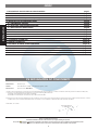
CE DECLARATION OF CONFORMITY
Manufacturer: GENIUS S.p.A.
Address: Via Padre Elzi, 32 - 24050 - Grassobbio- Bergamo - ITALY
Declares that: Operator mod. FALCON M
• is built to be incorporated in a machine or to be assembled with other machinery to create a machine under the provisions of Directive 98/37/EC;
• conforms to the essential safety requirements of the other following EEC directives:
73/23/EEC and subsequent amendment 93/68/EEC.
89/336/EEC and subsequent amendment 92/31/EEC and 93/68/EEC
Furthermore, the manufacturer declares that the machinery must not be put into service until the machine into which it will be incorporated or of which
it will become a part has been identified and its conformity to the conditions of Directive 98/37/EC has been declared.
Grassobbio, 10-11-2006
Managing Director
D. Gianantoni
Notes on reading the instruction
Read this installation manual to the full before you begin installing the product.
The symbol indicates notes that are important for the safety of persons and for the good condition of the automated system.
The symbol draws your attention to the notes on the characteristics and operation of the product.
INDEX
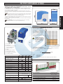
1. DESCRIPTION AND TECHNICAL SPECIFICATIONS page.7
2. DIMENSIONS page.7
3. MAXIMUM USE CURVE page.7
4. ELECTRONIC DEVICES (standard system) page.7
5. INSTALLING THE AUTOMATED SYSTEM page.8
5.1. PRELIMINARY CHECKS page.8
5.2. MASONRY FOR FOUNDATION PLATE page.8
5.3. MECHANICAL INSTALLATION page.8
5.4. INSTALLING THE RACK page.8
6. START-UP page.9
6.1. CONNECTION OF CONTROL BOARD page.9
6.2. POSITIONING THE TRAVEL-LIMIT ELEMENTS page.9
7. AUTOMATED SYSTEM TEST page.10
8. MANUAL OPERATION page.10
9. RESTORING NORMAL OPERATION MODE page.10
10. SPECIAL APPLICATIONS page.10
11. MAINTENANCE page.10
12. REPAIRS page.10
13. ACCESSORIES page.10

7
ENGLISH
2. DIMENSIONS
3. MAXIMUM USE CURVE
The curve makes it possible to
establish maximum work time (T)
according to use frequency (F).
With reference to standard IEC
34-1, the FALCON gearmotor,
with service type S3, can oper-
ate at use frequency of 40%.
To ensure efficient operation,
operate in the work range under
the curve.
Important: The curve is
obtained at a tempera-
ture of 20°C. Exposure to
the direct sun rays can
reduce use frequency
down to 20%.
Calculation of use frequency
The percentage of effective work time (opening + closing) compared to
total time of cycle (opening + closing + pause times).
Calculation formula:
Ta + Tc
% F = X 100
Ta + Tc + Tp + Ti
where:
Ta = opening time
Tc = closing time
Tp = pause time
Ti = interval time between one complete cycle and another
4. ELECTRONIC DEVICES (standard system)
FALCON AUTOMATED SYSTEM
These instructions apply to the following models:
FALCON 14 M - FALCON 14 MC - FALCON 20 M- FALCON 20 MC - FALCON
15 M - FALCON 15 MC - FALCON 20 M 3PH
The FALCON gearmotor for sliding gates is an electro-mechanical opera-
tor which transmits drive to the sliding leaf by a rack and pinion or by a
chain suitably coupled to the gate.
The non-reversing system guarantees mechanical locking of the gate
when the motor is not operating and, therefore, there is no need to install
any lock.
The gearmotor does not have a mechanical clutch and, therefore,
requires a control unit with an adjustable electronic clutch which
guarantees the necessary anti-crushing safety.
A handy manual release with a customised key makes the gate manoeu-
vrable in case of a power cut or trouble.
In the “C” version gearmotors, the electronic control unit is housed inside
the operator.
The FALCON gearmotor was designed and built for controlling
vehicle access. Do not use in any different way.
1. DESCRIPTION AND TECHNICAL SPECIFICATIONS
Foundation plate
Gearmotor
Enclosure and control unit
(In “C” versions only)
Magnetic sensor
Pinion
Release knob with key
Securing slots and nuts
Lateral protective devices
Covering housing
Pos. Description Connection cable
Gearmotor
3x2.5 mm
2
(230/115V~)
4x2.5 mm
2
(400V~)
Photocell transmitter 2x0.5 mm
2
(TX)
Photocell receiver 4x0.5 mm
2
(RX)
Key-operated selector switch 2x0.5 mm
2
Flashing light 2x1.5 mm
2
External receiver (optional) 3x0.5 mm
2
MODEL
14 M
14 MC
20 M
20 MC
15 M
15 MC
20 M
3Ph
Power supply (+6% -10%)
230 V~
50 Hz
115 V~
60 Hz
400 V~
50Hz
Absorbed power (W) 650 800 710 840
Absorbed current (A) 2.8 3.5 6.7 2.2
Electric motor (rpm) 1400 1700 1400
Thrust capacitor (µF) 16 20 60 /
Thrust on pinion (daN) 110 150 130 185
Torque (Nm) 35 45 38 60
Temperature protection (°C) 140 /
Max leaf weight (Kg) 1400 2000 1500 2000
Type of pinion gear Z 16 module 4
Gate speed (m/min) 10 11 10
Max. gate length (m) 20
Type of travel-limit device Magnetic
Type of clutch
Electronic torque control
(See control unit)
Use frequency (see graph) S3 - 40%
S3
50%
Operating ambient temperature (°C) -20 ÷ +55
Weight of gearmotor (Kg) 14 15
Protection class IP 44
Operator dimensions See fig. 2
Fig. 1
Fig. 2
Fig. 3

8
ENGLISH
5. INSTALLING THE AUTOMATED SYSTEM
5.1. PRELIMINARY CHECKS
To ensure safety and an efficiently operating automatic system, make
sure the following conditions are observed:
• The structure of the door must be suitable to be automated. Specifical-
ly, the wheel diameter must be in relation to the weight of the gate to
be automated; an upper guide must be present; travel-limit mechani-
cal stops must be fitted to prevent the gate derailing.
• The soil must permit sufficient stability for the foundation plinth.
• There must be no pipes or electrical cables in the plinth excavation
area.
• If the gearmotor is exposed to passing vehicles, install, if possible, ad-
equate means of protection against accidental impact.
• Check if an efficient earth socket is available for connecting the gear-
motor.
• Make sure that there is sufficient space around the operator to enable
all the installation jobs and subsequent maintenance work to be
smoothly carried out.
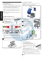
5.2. MASONRY FOR FOUNDATION PLATE
1. Assemble the foundation plate as
in Fig. 4.
2. The foundation plate must be
located as shown in Fig. 5 (right
closing) or Fig. 6 (left closing) to
ensure correct meshing between
rack and pinion.
When positioning the plate,
leave the Ø 80 hole for rout-
ing the sheaths on the left, as
shown in Fig. 5-6 ref. .
5.3. MECHANICAL INSTALLATION
Remove the motor cover, fully unscrewing the 2 upper securing screws
(Fig. 8 ref. ).
Rotate the cover by about 30° and pull upward.
Withdraw the 2 lateral protective devices (Fig.8 ref. ).
Fit the operator on the plate, using
the supplied washers and nuts as
shown in Fig.9.
During this operation, route the
cables through the slot on the
operator’s reduction element .
Adjust the height of the feet and the
distance from the gate - refer
to Fig. 10.
This operation is necessary to
secure the rack correctly and
to enable you, in future, to
make any height adjustments
to the motor.
Tighten the gearmotor securing screws.
Prepare the operator for manual operation as described in chapter 8.
5.4. INSTALLING THE RACK
5.4.1. STEEL RACK TO BE WELDED (FIG.11)
Fit the three threaded pawls on the rack
element, positioning them on the upper
part of the slot. In this way the clearance
on the slot will enable any adjustments
long-term.
Manually move the leaf to its opening
position.
Lay the first piece of rack level on the
pinion and weld the threaded pawl on
the gate as shown in Fig.13.
Manually move the gate, checking if the
rack is resting on the pinion and weld the second and third pawls.
Fit another rack element next to the previous one, using a piece of
rack, as shown in Fig.14 ref. , to synchronise the teeth of the two
elements.
Move the gate manually and weld the three threaded pawls. Carry on
like this until you have fully covered the gate.
Do not allow any superfluous sections of rack to project from the
gate.
3. Make a foundation plinth as in Fig. 7 and wall the foundation plate,
providing one or more sheaths for routing the electrical cables. Using
a spirit level, check if the plate is perfectly level. Wait for the cement
to set.
4. Prepare the electrical cables for connection to the accessories and
the electrical power supply as shown in Fig. 3.
To facilitate making the connections, make the cables come out
by about 40 cm from the foundation plate hole (Fig. 5-6 ref. ).
Fig. 8
Fig. 5
Fig. 6
Fig. 7
Fig. 4
Fig. 9
Fig. 10
Fig. 11

9
ENGLISH
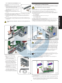
5.4.2. STEEL RACK TO BE SCREWED (FIG. 12)
Manually move the leaf to its opening
position.
Rest the first section of rack on the pinion,
positioning the spacer between the rack
and the edge of the gate. Using
a spirit level, check if the rack is horizontal
and mark the perforation point with a
felt-tipped pen.
Drill with a 6.5 mm diameter bit, and
thread with an M8 male element. Screw
the bolt.
Manually move the gate, checking if the rack is resting on the pinion
and repeat the operations in point .
Fit another rack element next to the previous one, using a piece of
rack, as shown in Fig. 14 ref. , to synchronise the teeth of the two
elements.
Move the gate by hand and perform the securing operations as for
the first element, carrying on like this until you have covered the gate
completely.
Do not allow any superfluous sections of rack to project from the
gate.
Notes on installing the rack
• Make sure that, during gate
travel,
all the rack elements do not
come out of the pinion.
• Do not, on any account, weld
the rack elements either to the
spacers or to each other.
• After you have finished install-
ing the rack, to ensure correct
meshing with the pinion, we
advise you to lower the position
of the gearmotor by about 1.5
mm (Fig.15).
• Manually check if the gate cor-
rectly reaches the travel-limit
mechanical stops and if there is
any friction during travel.
• Do not use grease or other lubri-
cants between rack and pinion.
6. START-UP
6.1. CONNECTION OF CONTROL BOARD
Before attempting any work on the board (connections, program-
ming, maintenance), always turn off power.
Observe points 10, 11, 12, 13 and 14 of the GENERAL SAFETY RULES.
Follow the instructions in Fig. 3, route the cables in the raceways and
make the electrical connections to the selected accessories.
Always separate power cables from control and safety cables (push-but-
ton, receiver, photocells, etc.). To prevent any electric noise whatever,
use separate sheaths.
6.1.1. EARTHING
Connect the earthing cable as shown in Fig. 16.
6.1.2. CONTROL UNIT
In the “C” version gearmotors, the electronic control unit is secured to an
adjustable support with a transparent cover.
The board programming push-buttons are located on the cover - this
enables you to program the board without having to remove the cover.
To connect the control unit correctly, follow the specific instructions.
6.2. POSITIONING THE TRAVEL-LIMIT ELEMENTS
To correctly position the travel-limit magnets, the control unit must
first be installed and correctly connected to all the command and
safety accessories.
The operator has a magnetic limit switch, which commands gate motion
to stop when the magnet, which is secured to the upper part of the rack,
activates the sensor. The magnets supplied with the operator are specifi-
cally polarised and activate only one of the sensor’s contacts: the clos-
ing or opening contact. The magnet activating the open gate contact
bears an open padlock symbol, and, vice versa, the magnet activating
the closed gate contact bears the closed padlock symbol (see Fig. 17).
Procedure for correct positioning of the two travel-limit magnets:
The operations described below refer to an installation with left
side closing (see Fig. 6). For installations with right side closing (see
Fig. 5), change over the two magnets on the rack.
Assemble the two magnets as shown in Figure 17.
Set the operator to manual mode operation - as per paragraph 8
- and power up the system
Manually take the gate to opening position, leaving 4 cm from the travel limit
mechanical stop.
Allow the magnet, with the padlock open, to slide , in opening direction on the
rack - see figure 18. As soon as the LED on the board, referring to the opening
limit-switch, goes OFF, take the magnet forward by another 10 mm and fasten
it with the appropriate screws (Fig. 18 ref. )
.
Fig. 13
Fig. 12
Fig. 14
Fig. 15
Fig. 16
Fig. 17

10
ENGLISH
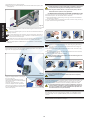
Do likewise for the closing magnet.
Take the gate to about halfway of its travel and relock the system (see
paragraph 9).
Before sending a pulse, make sure that the gate cannot be mo-
ved manually.
Command a complete gate cycle to check if the travel-limit device is
tripping correctly.
To avoid damaging the operator and/or interrupting operation of
the automated system, leave a distance of least 40 mm from the
travel limit mechanical stops.
Make sure that at the end of both the opening and closing ma-
noeuvre, the relevant travel-limit LED stays active (LED OFF).
Make the appropriate modifications to the positions of the travel-limit
magnets.
7. AUTOMATED SYSTEM TEST
Fit the lateral protective devices and re-position the motor cover, secur-
ing it with the appropriate screws (Fig. 19).
Apply the danger sticker on the top of
the cover (Fig. 20).
Check operating efficiency of the
automated system and all accessories
connected to it.
Hand the “Use Instructions” to the
Customer, explain correct operation
and use of the gearmotor, and indicate
the potentially dangerous areas of the
automated system.
8. MANUAL OPERATION
The manual release is a device that makes it possible to disconnect
the operator from the gate, thus enabling manual movement.
Before using the release device, cut power to the system, with the
differential switch upstream of the gearmotor.
THE RELEASE DEVICE MUST NOT BE CONSIDERED AN EMERGENCY STOP
If the gate has to be moved manually due to a power cut or fault of the
automated system, use the release device as follows:
1. Fit the supplied key in the lock, Fig. 21 Ref. , and turn it clockwise as
shown in Fig. 21 Ref. .
2.
Turn the release system clockwise by about 180°, as shown in Fig. 21 Ref. .
3. Open and close the gate manually.
9. RESTORING NORMAL OPERATION MODE
To prevent an involuntary pulse from activating the gate during
the manoeuvre, cut power to the system before re-locking the
operator.
1. Turn the release system anti-clockwise by about 180°, as shown in Fig.
22 ref. .
2. Turn the key anti-clockwise, Fig. 22 ref. , and remove it from the lock,
as shown in Fig. 22 ref. .
3. Move the gate until it meshes to release.
Before powering up the system again, make sure that the gate can-
not be moved manually.
10. SPECIAL APPLICATIONS
There are no special applications.
Anything not expressly specified in these instructions is expressly
prohibited
11. MAINTENANCE
To ensure correct long-term operation and a constant level of safety, we
advise you to generally control the system every 6 months. In the “Use
Instructions” booklet, there is a form for recording maintenance jobs.
The enclosed maintenance form is purely a guideline; it cannot be
ruled out that to guarantee a correctly operating automated sys-
tem and a constant level of safety, maintenance operations not
described in this form may be necessary.
12. REPAIRS
The User must not in any way attempt to repair or to take direct action
and must solely contact qualified GENIUS personnel or GENIUS service
centres.
13. ACCESSORIES
For accessories, see the GENIUS catalogue.
Fig. 18
Fig. 19
Fig. 20
Fig. 21
Fig. 22
Page is loading ...
Page is loading ...
-
 1
1
-
 2
2
-
 3
3
-
 4
4
-
 5
5
-
 6
6
-
 7
7
-
 8
8
-
 9
9


Ask a question and I''ll find the answer in the document
Finding information in a document is now easier with AI
in other languages
- italiano: Genius Falcon 5M
- français: Genius Falcon 5M
- español: Genius Falcon 5M
- Deutsch: Genius Falcon 5M
- Nederlands: Genius Falcon 5M
Related papers
-
Genius SPRINT11SW Operating instructions
-
Genius FALCON 5M 8M 424M Operating instructions
-
-
-
-
-
-
-
-