Page is loading ...

1
MXT Table of Contents
Chapter 1 Assembly...............................................................................2
Assembly Instructions .........................................................................................................................3
Chapter 2 Batteries.................................................................................4
Standard Battery Holder......................................................................................................................4
Using the
Standard Battery Holder...................................................................................................................4
Rechargeable Battery (Opt.)................................................................................................................5
Battery Check ......................................................................................................................................5
Chapter 3 MXT Quick Start ..................................................................6
Chapter 4 Display ..................................................................................8
Coin & Jewelry................................................................................................................................ 8-9
Relic .............................................................................................................................................10-11
Prospecting .................................................................................................................................. 12-13
Chapter 5 Controls...............................................................................14
Mode............................................................................................................................................ 14-15
Trac................................................................................................................................................16-17
Gain............... .............................................................................................................................. 18-19
Dual Control ................................................................................................................................ 20-22
Disc....................................................................................................................................... 20-21
SAT .............................................................................................................................................22
Threshold...........................................................................................................................................23
Chapter 6 Searching.............................................................................24
Pinpoint Technique............................................................................................................................24
Headphones .......................................................................................................................................25
Field Use & Tuning Tips "Coin & Jewelry"................................................................................ 26-27
Field Use & Tuning Tips "Relic" ................................................................................................ 28-29
Field Use & Tuning Tips "Prospecting" ...................................................................................... 30-31
Chapter 7 Information..........................................................................32
Proper Care........................................................................................................................................32
Service ...............................................................................................................................................33
Warranty ............................................................................................................................................34
Warranty Transfer..............................................................................................................................35
Video and Owner Information...........................................................................................................36
MXT Table of Contents

2
Assembly
Chapter 1 MXT Assembly
ELBOW
CUP
STRAP
ELBOW CUP
FOAM PADS
INSIDE ELBOW
CUP
CONTROL BOX
“S” ROD
LOOP CABLE
CAMLOCK
WASHERS
BETWEEN
EACH LOOP
EAR & CLEVIS
DISPLAY
TRIGGER
(behind display)
BATTERY
COMPARTMENT
DOOR
BATTERY
COMPARTMENT
LATCHES
LOOP
CONNECTOR
HEADPHONE
JACK
CLEVIS
LOWER
ROD
BOTTOM OF
CONTROL BOX
Twist and insert each end of
handle (provided) through top
of shipping carton into
second flap.
(CARRY CARTON)
CABLE RETAINER
LOOP OR SEARCH
COIL
Remove decal paper from the two rubber
bumpers. Install on the bottom of the
control box, one in each of the front corners
(shown below by "X"). Press in place and
hold firmly for a few seconds then release.
CABLE
RETAINER
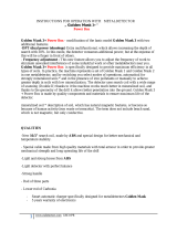
1/ VDI Numbers
2/ Target Identification
3/ Iron Probability
4/ Target Signal Strength
5/ Target Depth
6/ Pinpoint Location
7/ Battery Voltage
Target VDI
reference chart for
all three modes:
/Coin & Jewelry
/Relic
/Prospecting
Trigger behind display has multi-
function capability depending
on which of the three
modes you select

3
Chapter 1 MXT Assembly
Assembly Instructions
1. Remove all parts from shipping carton and
check the assembly page to make sure all parts are
present.
2. There are rubber washers between clevis/lower
rod and loop ears. Use only nonmetallic washers,
fiber bolt, and thumbnut to secure loop/search
coil to clevis/lower rod.
3. Unlock "S" rod camlock and insert clevis/
lower rod into curved "S" rod so that stainless
steel spring clip buttons line up and lock into one
of the adjustment holes in the curved "S" rod.
Turn camlock to secure. The second or third
adjustment holes are suitable for average size
adults. Individuals 6' or taller should use the fully
extended position. Individuals well over 6' tall
should purchase the optional Tall Man Rod.
4. Unravel loop cable and wind the cable around
the clevis and rod assembly, first revolution over
the top of the rod. Wind cable all the way to the
top of the curved "S" rod, about five revolutions.
Use the black cable retainers, one near the loop,
and one near the top of the curved "S" rod, to hold
the loop cable in place.
5. Unlock control box rod camlock and insert
curved "S" rod so that stainless steel spring clip
buttons line up and lock into the rod on top of the
control box. The "S" rod is designed to curve up
toward the display. However, those who prefer to
sweep the loop close to their feet may desire to
assemble the "S" rod to curve down toward the
ground. Turn camlock to secure. Plug loop con-
nector into control box, screw lock ring to secure.
6. Grip the instrument by the handle, with your arm in
the elbow cup with strap secure, and sweep the loop/
search coil over the floor. If the instrument fit feels
uncomfortable, adjust the elbow cup by removing
and repositioning the bolt/thumbnut and installing
in one of the optional positions. If necessary,
readjust clevis/lower rod length with the spring
clip buttons so that the search coil can be held near
the floor without requiring stooping over.
7. Remove the protective paper from the two black
elbow cup foam pads. Carefully align pads on the
inside of the elbow cup, one on each side of the
center rod, and press firmly into place.
8. Adjust the elbow cup strap so that it is loose
enough for you to slide your arm in and out with-
out loosening each time you want to set the detec-
tor down. The elbow cup strap provides extra
leverage and control. However, some prefer not to
use it.
9. Install battery as described in the next section,
decal facing down, with plastic tab and steel contacts
facing toward inside of battery compartment.
10. It should be noted at this point that the detector
may not work as expected indoors due to the high
degree of metals used in modern construction. It is
best to tune and practice out-of-doors to ensure
stable, predictable results. Additionally, freshly-
buried targets will not produce the normal depth
and discrimination results of targets that have been
naturally lost and settled in the ground. Due to the
abnormality caused by digging a hole in the ground
matrix, and the sophistication of the ground rejec-
tion circuitry, it may take a number of years for
freshly-buried targets to respond at true depths and
discrimination accuracy. The best way to deter-
mine true detection depth is in real search condi-
tions.

4
Batteries
Chapter 2 MXT Batteries
Using the
Standard Battery Holder
1. Slide open the battery holder lid (decal side of
battery holder) by applying gentle upward
pressure on the tab of the door so that it unlocks.
Slide the door away from the battery box
exposing the cell positions.
2. Remove any old cells from the holder. Note the
(+) and (-) positions of each cell and the (+)
and (-) for each position marked inside the cell
tray. Install new “AA” cells noting carefully the
correct (+) and (-) positions.
If the cells are installed incorrectly, the detector
may require service by an Authorized
Service Center.
3. Slide the door closed so that it snaps securely.
4. Insert the battery holder into the detector so that
the decal is facing down, with the battery
holder door tab and metal contact points facing
toward the inside of the battery compartment.
Close the battery compartment door and secure the
two latches on the bottom of the case. Hook the
front of each latch first, then press down on the
rear.
Standard Battery Holder
1. The standard battery holder holds eight “AA”
cell batteries equalling 12 volts total. Alkalines are
recommended for use with this model. During
normal searching conditions you can expect about
40 hours of hunting time from a quality set of eight
alkaline batteries.
2. Non-alkaline batteries can be used in this holder.
When non-alkalines or rechargeable “AA”
cells are used, detecting time (before replacement/
recharge) may be reduced to about 30-35
hours.
3. The battery voltage appears automatically on the
display when the Gain is used to turn the MXT
"ON". Once the batteries become weak (8 volts)
"Lo Bat" will automatically appear on the display
during searching. At that point the batteries should
be replaced. Alkalines provide some reserve time
after "Lo Bat" appears, rechargeable do not.
4. The battery compartment opens by gently
pulling down on the front of each of the two
latches (on the bottom of the control box) releasing
the catch and hinging open the door.

5
Chapter 2 MXT Batteries
Non-rechargeable batteries will start to drop in
voltage as soon as they are put into use and then
steadily diminish in voltage till they die. The Nicad
rechargeable battery pack, however, will diminish
very slowly (plateau) in somewhat of a flat line and
then drop like a rock.
Headphone use prolongs all battery life.
Battery life will vary a great deal with temperature,
number of target signals, battery type, brand, and
shelf life.
Alkaline Batteries may be used (in a pinch) well
into the "LoBat" indication. Rechargeables can not.
When traveling far from home it is always a good
idea to carry 8 extra penlight alkaline batteries with
you.
Rechargeable Battery (Opt.)
A rechargeable battery system is not standard
equipment with your MXT, however, high quality
systems are available.
White's rechargeable battery #802-5211, and
charger #509-0022 are recommended and offer
quick charge and overnight charge options.
Rechargeable batteries deliver fairly constant
voltage until they're nearly dead. If you use them
until they are dead, they will deteriorate more
quickly than if you only use them till their voltage
starts to drop significantly. Therefore, recharge-
ables should be taken out of service and recharged
as soon as you notice "LoBat" on the display.
Rechargeable batteries will not provide the same
amount of continuous use as a new set of Alkaline
batteries.

6
MXT Quick Start
Chapter 3 MXT Quick Start
MODE Toggle
Three position switch for
setting operating mode.
Coin & Jewelry, Relic, Prospecting.
GAIN Control
Turns the MXT ON/OFF and adjusts the
signal strength of targets, ground, and
electrical interference.
DUAL CONTROL
In Coin & Jewelry and Relic Modes
establishes the level of trash metal rejection
(Discrimination). In the Prospecting Mode
establishes Self Adjusting Threshold
(SAT), the speed at which the THRESH-
OLD "hum" recovers from the affects of
inconsistencies in ground mineralization.
THRESHOLD Control
Establishes the slight background sound "faint
hum" or edge of sound, that is heard continu-
ously during searching. Once this edge of sound
has been located some operators prefer to adjust
slightly counterclockwise of it to achieve silent
search, no continuous background hum, during
searching.
TRAC Toggle
Three position switch for setting
Ground Mineral Tracking. Salt,
Lock (hold), and Ground.
Trigger Switch has three positions;
1. Forward (Alternate Mode).
2. Center (Primary Search).
3. Squeeze and Held (Pinpoint).
1
2
3
4
5
6

7
Chapter 3 MXT Quick Start
Quick Start
Instructions
With the MXT properly assembled and the
batteries installed, follow the instructions below to
start finding treasures!
Set the Ground Balance Toggle to the
Ground position. "▼"
Set the Trigger Switch (under the hand
grip) to the center (Primary Search)
position.
Set the MODE toggle to the position that
best describes your searching desire,
Coin & Jewelry, Relic, or Prospecting.
Set the DUAL CONTROL to the DISC
ring "▼" for Coin & Jewelry and Relic
Mode or to the SAT ring "▼" for
Prospecting Mode.
Turn the GAIN control clockwise until the
power clicks "ON". Rotate the GAIN
control clockwise to "▼".
Adjust the THRESHOLD control until you
hear a soft threshold "hum" (faint sound).
Lower the search coil to the ground, then
“pump” the coil up and down 2"-4" a
couple of times and Fast AutoTrac will
automatically balance or track out the
ground mineralization.
Start swinging the search coil in wide
sweeps that overlap each other as near the
ground surface as possible.
If you experience false signals or constant
beeping or popping and you are not near
common sources of electrical interference,
set TRAC to LOCK and/or reduce GAIN
(counterclockwise) slightly and try again.
It is normal to hear very slight fluctuations
in the THRESHOLD “hum” as the MXT
tracks out the ground mineralization.
When operating in the Prospecting Mode,
first try reducing the Gain and/or increasing
the SAT speed. SAT speeds as high as
HYPERSAT may be necessary in some
ground conditions. If Gain and SAT
adjustments do not smooth performance,
then switch to the Trac Lock position.
1
2
3
4
5
6
7
8
9
* SPECIAL NOTICE* SPECIAL NOTICE
* SPECIAL NOTICE* SPECIAL NOTICE
* SPECIAL NOTICE
If you attempt to demonstrate or test the
MXT by waving targets in the air in front
of the search coil, it is ESSENTIAL to
have the GROUND BALANCE toggle in
the Lock position, NOT Ground or Salt.
This is necessary, for when the MXT is in
the Ground or Salt positions, the search
coil must SEE ground while it is passing
over the target or it will think that the
target IS ground and will attempt to track
it out. This is the case in all MODEs.
You may, however, demonstrate the fast
ground balancing feature of Ground or
Salt by waving or pumping a mineralized
rock in the air in front of the search coil.
Testing the MXT with targets while in
TRAC Ground or Salt positions must be
done in or on the ground.
7
8

8
Chapter 4 MXT Display
MXT Display Indication
The MXT display and reference label below the
display provide a wealth of information about the
metal target. It is important, however, to understand
the display information should only be consulted
after a solid repeatable audio tone "beep" has been
located.
The MODE selection changes the type and content
of the information shown by the display better
suiting the MXT to the application, Coin & Jewelry,
Relic, or Prospecting.
In all MODEs, the display will momentarily show a
software version and battery voltage upon first
turning the GAIN "on". The MXT operates on a
twelve volt battery system which with new quality
batteries will indicate 12 + volts. During searching
"LoBat" will start appearing on the display at 8
volts and anything 8 volts and below are suspect for
replacement. If using rechargeable batteries 8 volts
is surely the end of their performance. If you are
using quality alkaline batteries you do have a
reserve after 8 volts. The MXT utilizes a low
voltage regulator. Quality alkaline batteries will
provide normal performance (in a pinch) well into
the LoBat indication.
Coin & Jewelry MODE;
The Coin & Jewelry MODE provides 5 different
significant indications on the display.
1. VDI = number - The VDI (Visual Discrimina-
tion Indication) is a reference number dictated
mostly by the metals targets exact alloy, size, and
shape. The reference label below the display
provides a comparison of known targets and their
common VDI numbers. Like targets produce like
VDI numbers. Similar targets produce similar VDI
numbers. And different targets produce different
VDI numbers. Different metal targets, however,
may share the same VDI numbers based on their
electrical characteristics. VDI numbers from -95 to
+94 are available and cover the entire range of
alloys and sizes.
VDI number on display
VDI number range on reference label
Mode toggle switch
forward for Coin and
Jewelry

9
2. Blocks - A series of 16 blocks appear along the
bottom portion of the display and line up with the
indications on the reference label below the display.
It is important to note these blocks are a different
separate opinion compared to the VDI number and
they may or may not agree. There is significance to
how these blocks appear. A full block indicates the
MXT is confident of indication. A half block indi-
cates the MXT is not confident but is making an
educated indication. A quarter block indicates the
MXT is not confident at all, guessing based on what
little information the target is producing.
3. Labels - The most common metal target (or
targets in some cases) to indicate that particular
Block is listed on the display as well as referenced
in an expanded format on the label below the
display. If two targets are listed the first to be listed
is the most common and the second listed slightly
less common than the first.
4. Depth Indication - Trigger (on hand grip)
squeezed and held, the display indicates the depth
of coin sized metals. Starting at 12 inches and
indicating in descending order (as the target gets
closer to the bottom of the search coil) the DEPTH
= 12 provides not only an aid in better locating the
target in the ground (how deep you will need to dig)
but also clues as to if the metal target is likely worth
digging. For example if the display is unsure
(quarter block indication), is indicating in the FOIL
range, and the depth reads deep 6 to 12 inches, you
should dig the target. Only the heavier more valued
targets get deeper into undisturbed ground. If the
display reads unsure (quarter block), indicates in the
FOIL area, and the depth reads shallow 0 to 2
inches, the target is most likely not worth digging.
Foil will not sink deeply into undisturbed ground.
Targets that indicate depth readings from 3 - 5
inches are not as predictable.
5. PP Blocks - Trigger (on the hand grip) squeezed
and held, the PP blocks aid in pinpointing the exact
center of the metal target. Only when the search coil
is directly over the center of the metal target (long-
est possible length PP Blocks) is the depth reading
giving you the most accurate depth indication. Also
of importance is that with some experience the
relative size and shape of the metal target can be
recognized during pinpointing.
Chapter 4 MXT Display
Note: Dotted blocks for illustration purposes only.
Half block indicating MXT is not certain but possible.
Note: In this case, the 1¢ is the probable ID.

10
Chapter 4 MXT Display
Relic MODE;
The Relic MODE also provides 5 different signifi-
cant indications on the display.
1. VDI = number - As with the Coin and Jewelry
mode the relic VDI (Visual Discrimination Indica-
tion) is a reference number dictated mostly by the
metal targets exact alloy, size, and shape. And just
like coins and jewelry, relics can present with
similar VDI numbers for different objects because
their makeup and electrical charasteristics are
similar. Using the reference label below the display
one can see that iron relics are still in the low VDI
numbers and objects like brass buttons and buckles
with a high concentration of non-ferrous metal or
alloy rate higher VDI numbers compared to their
size and purity.
2. Blocks - The MXT Relic mode uses the same
sixteen filled in Blocks as Coin and Jewelry mode
to further confirm, on the reference label, the
connection between the VDI number and software's
best determination of the target identity. The verti-
cal size (one quarter, one half, or the whole block)
tells one how sure the MXT is of the target ID. Full
bar and half bar usually means dig. Quarter blcoks
are uncertain.
3. Labels - In Relic mode you will see target ID
labels in the upper right of the display. The labels
are Hot Rock, IRON, BUTTON, BULLET and
BUCKLE. Obviously there are many more relic
items possible. Just keep your imagination open for
what possible objects were produced in metal and
how they might compare in size and alloy to the
ones mentioned above.
Chapter 4 MXT Display
NOTE: The filled in block and the VDI number are
separate opinions by the software and may agree or
disagree.
NOTE: The top
display is a sure
ID. The bottom
display with its
quarter size bar
suggests uncer-
tain unless
theDepth reading
is 6-12.
Mode toggle
switch Center
for Relics

11
5. PP Blocks - Relic mode Pinpointing works the
same as in Coin and Jewelry mode. With the trigger
(on the hand grip) squeezed and held, the PP (pin-
point) blocks aid in pinpointing the exact center of
the metal target.
4. Depth Indication - Trigger (on hand grip)
squeezed and held, the display indicates the depth
of coin sized metals. Just as in the Coin and Jewelry
mode, Depth not only tells you how deep the target
is but combined with the block reading and target
label on the right side of the display it can indicate
if the item is worth digging. A 6 - 12 Depth reading
and any Block indication means dig. Shallower
targets and a quarter or half size block suggests
trash. This is because the heavier more desirable
targets settle deeper into undisturbed ground. The
shallower Depth readings should have full Blocks
to warrant digging.
Chapter 4 MXT Display
NOTE: Before
squeezing the
trigger, the
quarter Block
reading says
the MXT is
not sure. A
Depth reading
can help
you decide to
dig or not.
A depth of
10 sug-
gests you
should dig.
In this case a
depth of 3
with only a
quarter block
filled sug-
gests the
target is
questionably
trash.
NOTE: Please refer to page 24 for the proper "X" ing
technique to "Pinpoint" the exact center of the target.

12
Chapter 4 MXT Display
Prospecting MODE
The Prospecting MODE changes the display infor-
mation significantly.
Gold in it's natural state can be any size and shape
from very tiny pinhead size flakes to large placer
gold nuggets as well as veins of various size in
quartz rocks. The Prospecting MODE takes these
facts into consideration and changes the display
accordingly. When prospecting an operator must
expect to dig nonferrous (not of iron) trash metals
such as aluminum foil, lead, and small brass. Any
of these metals can and do elicit the same response
as gold and MUST BE DUG. Attempts should be
made to avoid only IRON targets and only when
possible. The MXT displays information which is
intended to help the user determine whether the
target is NON-IRON (dig) or IRON (don't dig). In
heavy mineralized ground tiny pieces of gold can
sometimes look like IRON to a metal detector and
small pieces of IRON can look like gold. The VDI
numbers and Iron Probability scale both provide
help in determining when to dig.
The Prospecting MODE provides four significant
display indications.
1. VDI - The VDI number is listed on the display
and referenced on the label below the display. Gold
can indicate anywhere from slightly negative to +80
on the scale, however, most small nuggets indicate
in the -20 to +40 range. Metals that indicate above
+80, or below -20 are highly unlikely to be gold
unless they are conglomerated with highly unusual
alloys. If the VDI number tends to jump back and
forth from small negative numbers to small positive
numbers it is usually a small piece of some metal
and should be investigated by digging. Remember,
small flakes of gold in bad ground can read into the
small negative range. A magnet on your digging
pick can sort out a small shard of iron quickly.
2. IRON TARGET? - Indicates the likelihood the
target is ferrous (iron) expressed in a %. This
indication can be different in different areas de-
pending upon the degree of mineralization. As a
general rule targets registering 60%, 70%, 80%,
90% are going to be iron. 80% and over will
produce the audio grunt in the primary (Trigger
Center) mode. Targets that register 10%, 20%, 30%
or 40% are going to be gold or (lead, copper, alumi-
num, brass). All targets registering 50% or below
should be investigated.
As mentioned under the VDI section, iron ground
mineralization can distort the way the detector
reacts to gold. It is always a good idea to place a
test nugget just under the surface of the ground
whereever you are going to be prospecting and note
how it reacts to the IRON TARGET %. This will
give you a gauge as to what to expect. The degree
of dependability is affected by ground minerals and
the size of the target. It is not uncommon for a
small piece of gold in very bad ground to read 70%
probability of being iron. Remember when in
doubt...DIG. Use both the VDI and % IRON
PROBABILITY. Dig often at first, till you get a feel
for the area and accuracy in that ground.
NOTE: The display reading above would indicate a
target with a proper VDI number for gold and a low
enough iron target percentage to dig.
Mode toggle
switch Down for
Prospecting

13
Chapter 4 MXT Display
Ground phase indications are a doubled edged
sword. Higher numbers simply mean predominately
ferrous (iron) such as black sands / magnetite.
Lower numbers simply mean less iron and/or
predominately conductive nonferrous (not of iron)
content, such as gold per ton of rock. So in a dry
wash, outcropping, or vein, a shift in either direc-
tion (higher or lower numbers) may be of interest.
For example a black sand streak may have a lot of
flour gold at one end. It will indicate a high ground
phase number on the end without the flour gold, and
a lower ground phase on the end with the flour
gold. The same applies to veins or anoutcropping.
It is the change that brings about the interest more
so than if it is either high iron (high number) or
high conductive (lower numbers). Knowing that the
ground is high iron (magnetite), outlining black
sand pockets, and checking veins for consistency
(change), and comparing rock samples for possible
assay, are the common uses of ground phase.
Again, change is of the most interesting, not direc-
tion.
3. GND - Indicates the phase (measurement) of the
ground . This is useful in two different environ-
ments.
A. Within a dry wash the gold will settle
with the heavier materials (black sands).
When searching you notice the ground
phase is declining (lowering in number),
generally you are working further away
from the heavy black sand deposits. If you
notice the ground phase is increasing,
generally you are working toward (closer) to
the heavier deposits. By following the more
intenseground phase you increase your
likelihood of finding nuggets.
B. Checking outcropping or veins, the
ground phase can also be useful in a similar
way by indicating the consistency or change
of the veins ground phase.
Generally speaking, the ground numbers will hold
fairly consistent in most open terrain areas, such as
hydraulic sites and desert areas. GND readings in
the high 70's and 80's are considered heavy iron
mineralization. Alkali or salt areas will display
much lower numbers, possibly into the 30's and
40's.
Black sand streak-heavy iron mineralization
Alkalai or salt area in a dry wash
Flour gold
concentration
at one end of
black sand streak
NOTE: Watching the change in Ground Number in the upper right of the display, you will first look
for a change to a high number indicating high mineralization or black sand. When that streak is
identified you will then look for the Ground Number to lower again at one end of the streak indicat-
ing where the flour gold concentrated or washed down to that end.
Use Ground Numbers First to Find Gold Bearing Ground in a Dry Wash

14
MODE
COIN & JEWELRY MODE
*Trigger (on hand grip);
Center Position "Primary Searching" (tradi-
tional DISC control) . In other words with the
Trigger on the hand grip in the center position, the
DISC control works like most traditional metal
detectors in that metal items below the DISC con-
trol setting are suppressed (quiet or broken) by the
audio and metal items accepted by the DISC control
setting produce a smoother solid audio beep.
Forward Position (Alternate Mode) "Pull Tab
Range Notched Out (suppressed)".
In other words with the Trigger on the hand grip in
the forward position, the typical pull tab range is
rejected regardless of the DISC controls position.
If you are accepting nickels, pull tabs above that
setting on the DISC control range are still sup-
pressed (quiet or broken) by the audio.
Squeezed and held "Pinpointing/Depth Read-
ing". When operating in the Coin & Jewelry
MODE when the Trigger on the hand grip is
squeezed and held, the display provides a screen
that indicates the depth of coin sized targets. Once
released the trigger will automatically return to the
Center "Primary Search" position.
*DUAL CONTROL DISC "P" Preset
While operating in the Coin & Jewelry MODE The
DUAL CONTROL functions as a traditional dis-
crimination control. Further clockwise settings
provide greater degrees of trash metal rejection.
Further counterclockwise settings provide lesser
degrees of trash metal rejection.
Controls
The MODE toggle selects the operating MODE or
type of searching desired on that particular outing.
Major changes occur with the selection between the
three available operating MODEs. For example the
function and information of the display changes
between the three MODEs, the function and avail-
able features of the TRIGGER switch on the hand
grip changes between the three MODEs, and the
DUAL CONTROL function changes between the
MODEs. For quick field reference, the silk screen
painted on the bottom of the control box is provided
to simplify these changes and features.
Further explanation is provided as follows;
MODE Toggle
Chapter 5 MXT Controls
Chapter 5 MXT Controls

15
Chapter 5 MXT Controls
RELIC MODE
*Trigger (on hand grip)
Center Position "Primary" "Two Tone ID" (disc
accept high tone, reject low tone).
In other words while operating in the Relic MODE,
targets below the DISC control setting produce a
beep lower in pitch, targets above the DISC control
setting produce a beep higher in pitch. Two differ-
ent tones, lower trash/rejects, higher good metals,
accepts all based on the DISC control setting. Edgy
target responses are normal for this mode as it
technically is a Mixed Mode with all metal and Disc
working simultaneously. Unlike other White's
models some loop motion is always required for
good target responses. Targets singles that are not
readily identifiable are assigned a tone between the
two, Threshold pitched.
Forward Position (Alternate Mode) "DISC
Suppresses Rejects" (at "0" DISC iron low tone/
non-iron high tone).
While operating in the Relic mode with the Trigger
on the hand grip in the forward position, and the
DISC control set in any typical trash rejection
setting, discrimination against trash metals occurs
like any traditional metal detector in that metals
below the Disc setting are suppressed (quiet or
broken) and metals above the DISC setting produce
a smoother solid beep. With the trigger forward
and the DISC control set to ZERO, however, fer-
rous metals (iron) produces a lower pitch beep and
nonferrous metals (not iron) produce a higher pitch
beep.
Squeezed and held "Pinpointing/Depth Read-
ing".
When operating in the Relic MODE when the
Trigger on the hand grip is squeezed and held, the
display provides a screen that indicates the depth of
coin, medium button, medium bullet sized targets.
Once released the trigger will automatically return
to the Center "Primary Search" position.
*DUAL CONTROL DISC Preset.
While operating in the Relic MODE the DUAL
CONTROL functions as a traditional discrimination
control. Further clockwise settings provide greater
degrees of trash metal rejection. Further counter-
clockwise settings provide lesser degrees of trash
PROSPECTING MODE
*Trigger (on hand grip) - Center Position "Pri-
mary Searching" (iron audibly grunts).
While operating in the Prospecting MODE, iron
targets 80% and over produce an audio grunt when
detected.
Forward position (Alternate Mode) "Without
Iron Grunt" (all targets same audio).
The audio produces the same basic VCO audio
beep (zip sound) regardless of metal type. Iron
doesn't grunt.
Squeezed and held "Temporally Disables (stops)
ground tracking".
Depth reading can only accurately be calibrated by
knowing ahead of time approximate target size. No
two nuggets are the same size so any attempts to
apply depth indications are fundamentally flawed
(in error). Therefore while operating in the Pros-
pecting MODE rather than giving a known flawed
depth indication, squeezing and holding the Trigger
on the hand grip simply and temporarily stops
ground tracking. This is an important feature. In
order for the MXT to recognize a target in mineral-
ized ground it must first be able to cancel the
ground mineral. This is done by the fast tracking
system built into the software. It must actually see
ground with every sweep (on either side of the
target) in order to separate the target from the
ground. This is easily done during the normal
process of detecting. However, when a target has
been detected, the user usually hovers for a while
over the target and makes repeated passes in order
to decide whether or not to investigate the signal.
thus, analyzing audio and display information. This
hovering can often cause the detector to see more
target than ground and cause the detector to think
the target is ground and attempt to track into it.
Squeezing and holding the trigger when analyzing
the signal stops tracking and prevents errors.
*DUAL CONTROL SAT Preset.
While operating in the Prospecting MODE, the
DUAL CONTROL functions as a Self Adjusting
Threshold (SAT) control to smooth inconsistencies
in the ground and thus the Threshold. More on SAT
under the section dedicated to the DUAL CON-
TROL.
Chapter 5 MXT Controls

16
Chapter 5 MXT Controls
TRAC TOGGLE
TRAC Toggle
The TRAC toggle selects the type of ground
mineral rejection (ground balance) and automatic
tracking to ground mineral changes best suited to
the specific area. Three different positions each for
a specific ground condition (ground type) are
provided.
The Ground position is used for normal or typical
ground conditions. In this position the MXT will
quickly compensate for ground minerals in a few
pumps of the search coil over the ground being
searched and quickly (automatically) track to any
ground changes as you sweep the search coil during
searching. For most operators the Ground position
will be used for over 90% of your searching condi-
tions.
The Lock position monitors, however, doesn't track
to changing ground conditions. Man made iron
decomposes to the point of tricking the Ground and
Salt position tracking into thinking it is a mineral-
ized part of the ground. This can create noise and
instability during searching as the tracking system
bounces radically up and down the scale, always
searching for a good ground rejection setting and is
never able to find it. This makes it difficult for an
operator to recognize worthwhile targets and/or run
at the higher performance GAIN settings. In these
conditions it is recommended to first go to the
Ground position and pump the search coil over a
clean area of ground representative of the area (free
of man made iron) then switch the TRAC control to
Lock. By doing so stability and success searching
these trashy areas will improve dramatically. Be-
cause ground changes are monitored during Lock,
once an operator switches back to either Ground or
Salt tracking positions, updates to an appropriate
ground setting are virtually instantaneous.
Chapter 5 MXT Controls

17
Another example of when Lock would be used is if
a particular mineralized rock or patch creates
difficulties in searching an area. A hard rock mine
for example with a low mineralized base rock and
random high mineralized rocks or patches. Place
the TRAC control in the Ground position and
balance "pump the search coil" over a representa-
tive sample of the high mineral rock or patches.
Then Lock in that ground rejection setting "place
the TRAC control in the Lock position". The entire
area can then be searched without the distraction of
the inconsistencies the high mineral patches create.
The Salt position provides an extended ground
balance and tracking range to compensate for
conductive salts also called alkali. Ground rejection
against salt/alkali slightly overlaps the lower end of
the conductive target (metal) range. In other words
if you ground balanced against significant salts,
some loss of sensitivity to lower conducting metals
(metals low on the VDI target scale) can be ex-
pected. The advantage and performance improve-
ments of rejecting the salt, however, far outweighs
any loss. Because the Salt TRAC setting can track
well into the target range it is not recommended for
normal conditions, only for areas known to contain
salt. Salt water beaches for example or alkali desert
regions. The Ground setting will not track into the
nonferrous metal region. The Salt setting will. The
MXT ground rejection system is capable, in both
the Ground and the Salt settings, of considering
some iron a ground mineral.
If operating in a known salt area, salt water beaches
for example, it is not necessary to balance in the
Ground TRAC setting. Simply select the Salt
TRAC setting and proceed to pump the search coil
over the ground to be searched. The Salt setting
will balance and then track to changes identically to
the Ground setting only with an extended range,
well into the conductive target area.
Summary - The Ground TRAC setting is recom-
mended for most searching conditions. Lock is
used to hold a ground rejection setting that is first
established in the Ground or Salt TRAC positions.
Lock is recommended for areas that cause detector
instability due to extreme ground peculiarities such
as a lot of decomposing man made iron. Salt pro-
vides extended ground rejection range to compen-
sate for conductive salt/alkali conditions. The Salt
setting can ground cancel extreme enough to reduce
sensitivity to low conducting metals, metals that
appear low on the VDI scale. The Ground TRAC
setting will not balance nor track into the nonfer-
rous metal region. Despite this draw back the Salt
setting still provides improved overall performance
while operating in the salt/alkali ground condition.
Chapter 5 MXT Controls
Chapter 5 MXT Controls

18
Chapter 5 MXT Controls
Gain Control/ON-OFF
With the GAIN control, you turn the instrument on/
off and select the signal strength. You might expect
increased signal strength to always find more at
greater depths. However, high ground mineraliza-
tion will "bounce" the signal back and mask good
targets. It is therefore necessary to ADJUST the
GAIN to give you the maximum allowable GAIN
without masking targets or overloading the circuit
and at the same time allowing you to operate the
detector with a constant faint threshold hum so that
faint signals (deep or small targets) can be detected.
This is where the new MXT can help you out.
When ground mineralization is too high for the
current GAIN control setting, the display indicates
"OVERLOAD-REDUCE GAIN/LIFT LOOP"
along with an audible "squawk". Reduce the GAIN
till the overload warning ceases. On occasion,
while searching, you might sweep the loop over a
very large or very shallow target. The message on
the LCD display will read "OVERLOAD-RE-
DUCE GAIN/LIFT LOOP". All such targets
should be checked by sweeping the loop a little
higher over the area and noting the display and
audio indications. The MXT will self correct after
the message and you can continue to search as
normal.
Gain Adjustment
1. The GAIN control knob turns the MXT ON and
OFF and controls the GAIN. Starting from the
POWER OFF position and going clockwise, the
power is turned ON and the dial increases the
GAIN from a minimum level of "1" to a maximum
level of "+3". Set the control to the "Initial Setting
Triangle" ( between level 9 & 10 ).
2. Although the setting of (9-10) gives more than
ample GAIN, if the ground mineralization is low
enough, you might attempt to raise the GAIN above
this level toward +3.
GAIN Control
NOTE: Ground Mineralization too high, large or shallow target
message.
Chapter 5 MXT Controls

19
Gain Adjustment (continued)
5. In the Prospecting MODE the use of the SAT
(variable self-adjusting threshold) control will help
to maintain a smooth THRESHOLD "hum" par-
ticularly at higher GAIN settings and will be
covered in a later section.
6. While using a steady slow search coil sweep
speed, simultaneously advance GAIN towards
"+3". If the "OVERLOAD-REDUCE GAIN/
LIFT LOOP" alert keeps popping up on the
display, if a quiet smooth background THRESH-
OLD "hum" doesn't continue, or if ground noises
are a problem reduce GAIN.
7. The trash I.D. capability of the MXT also func-
tions more accurately when the GAIN is set at a
level which allows for smooth operation. Too
much GAIN can cause bad ground to distort the
proper identification of iron and non-iron targets.
8. Note: It is normal to hear changes, clicks or soft
beeps, coming from the audio (speaker) during
GAIN adjustments as the circuit shifts between
hardware and software gains (different electrical
parts of the circuitry). The GAIN control adjusts
both the hardware gain (hard physical component)
as well as the software gain (computer code)
alternating between the two throughout it's range.
As the MXT shifts between these two intricate
parts of the circuitry an audio indication notes the
transitions. This can be helpful. If you adjust the
Gain slightly, the audio notes a significant rather
than slight change.
9. The MXT provides more GAIN control range
than is typically useful assuring performance is not
left on the plate due to restricted assess/range.
Likely few areas will allow maximum GAIN (full
clockwise) without at least some degree of radical
(noisy) operation. Setting in the + area requires a
high degree of operator skill.
SAT SPEED CONTROL
(Prospecting Mode Only)
Chapter 5 MXT Controls
GAIN Control
Gain Adjustment (continued)
If, of course, "OVERLOAD-REDUCE GAIN/
LIFT LOOP" message is displayed common for
very nasty ground mineralization, you must heed it
and reduce the GAIN rather than raise it.
3. The object of increasing the GAIN is to get the
maximum available depth from the detector WITH-
OUT causing the "OVERLOAD-REDUCE
GAIN/LIFT LOOP" message to appear which
indicates an overload of the circuit.
4. In addition, any increase in GAIN adjustment
should NOT BE at the expense of maintaining a
smooth and constant THRESHOLD "hum". False
signals, beeps and static from bits of mineralization,
erratic behavior, and lapses in THRESHOLD all
can be the result of running with too much GAIN.
Chapter 5 MXT Controls

20
DUAL CONTROL
DISC -DISCRIMINATION (outer ring)
When in COIN & JEWELRY and RELIC MODE
VARIABLE SELF ADJUSTING THRESHOLD SPEED (SAT)
When in Prospecting MODE.
While operating in the Coin & Jewelry or Relic
MODEs the Dual control operates as a DISC
(discrimination ) control.
DISC (Discrimination) is used to adjust the level of
audio rejection against trash metals.
The "P" (Preset) just below NICKEL is recom-
mended for most general purpose searching. In this
position, the detector will provide a reject response
to most iron and light foil and respond to most
valuables including jewelry.
Positions lower than "P" (counterclockwise)
provide less trash metal rejection, to the point of
detecting virtually all types of common metals.
Positions higher than “P” (clockwise) will reject
more trash metals including aluminum pull tabs.
The display will continue to indicate I.D. even
though the audio discriminator will signal with a
reject (suppressed or broken) sound. Nickels and
some jewelry will also be rejected with DISC
settings much greater than "P".
The "P" position is recommended for most
MODES. If when searching at the "P" position you
feel you are digging too much trash, adjust DISC
slightly clockwise and try again. Finding the lowest
(furthest counterclockwise) position that eliminates
the common trash metals in your area is important
in order to find items of jewelry.
The MXT provides six significantly different DISC
(Discrimination) modes.
1. Traditional DISC mode is available;
A. In the Coin & Jewelry MODE with the
Trigger on the hand grip in the center
position
B. And in the Relic MODE with the Trigger
in the forward position (with the DISC
control set for typical trash rejection).
Dual Control
Chapter 5 MXT Controls
Chapter 5 MXT Controls
/