Page is loading ...

45030A
WOOD STOVE MANUAL
STOVE BUILDER INTERNATIONAL.
250, rue de Copenhague,
Saint-Augustin-de-Desmaures
(Quebec) G3A 2H3
Tel.: 418 878-3040
Fax: 418 878-3001
WWW.DROLET.CA

2
TABLE OF CONTENTS
INTRODUCTION........................................................................................................................... 3
THE DROLET WOOD STOVE MANUAL .................................................................................. 3
WOOD HEATING ...................................................................................................................... 3
THE CONTROLLED COMBUSTION WOOD STOVE ........................................................... 3
ASSEMBLING THE STOVE ..................................................................................................... 4
INSTALLING THE FIREBRICKS ............................................................................................. 5
INSTALLATION OF YOUR DROLET WOOD STOVE .......................................................... 6
POSITIONING THE STOVE .................................................................................................. 6
FLOOR PROTECTION .......................................................................................................... 6
CLEARANCES TO COMBUSTIBLE MATERIALS ................................................................ 7
REDUCED CLEARANCES .................................................................................................... 8
STEP BY STEP INSTALLATION OF YOUR CHIMNEY ..................................................... 12
COUPLINGS......................................................................................................................... 19
AIR CIRCULATION SYSTEM ............................................................................................... 21
BAFFLE BRICK INSTALLATION (SAWMAN STOVE ONLY) .......................................... 21
OPERATING YOUR DROLET WOOD STOVE .................................................................... 22
FUEL..................................................................................................................................... 22
IGNITION ............................................................................................................................. 23
MAINTENANCE OF THE HEATING SYSTEM .................................................................... 25
MAINTENANCE OF THE STOVE ....................................................................................... 25
MAINTENANCE OF THE CHIMNEY .................................................................................. 26
PROCEDURES IN CASE OF FIRE ......................................................................................... 26
FREQUENTLY ASKED QUESTIONS ................................................................................... 27
WHAT DO THE WORDS “DRAFT” AND “NEGATIVE PRESSURE” MEAN? ................. 27
CAN I MODIFY MY STOVE TO INSTALL A GLASS DOOR? ............................................ 33
WHEN DO IN NEED TO REPLACE THE FIREBRICKS? .................................................. 33
DROLET LIMITED LIFETIME WARRANTY ........................................................................... 34
REGISTER YOU WARRANTY ONLINE
To receive full warranty coverage, you will
need to show evidence of the date you
purchased your stove. Keep your sales
invoice. We also recommend that you
register your warranty online at
www.drolet.ca
Registering your warranty online will help us
track rapidly the information we need on your
insert.

3
INTRODUCTION
THE DROLET WOOD STOVE MANUAL
SBI INC., one of the most important wood stove and fireplace manufacturers in North America, congratulates
you on your purchase and wishes to help you get maximum satisfaction from the wood stove you have
selected. In the pages that follow, we will give you advices on wood heating and controlled combustion as
well as technical specifications regarding installation, operation and maintenance of the model you have
chosen.
The instructions pertaining to the installation of your wood stove comply with ULC #S627 standards. You
must follow them very carefully in order to eliminate any chance of encountering major problems.
Read this entire manual before you install and use your new stove. If this stove is
not properly installed, a house fire may result. To reduce the risk of fire, follow the
installation instructions. Failure to follow instructions may result in property
damage, bodily injury or even death.
PLEASE CONSULT LOCAL AUTHORITIES, BUILDING DEPARTMENT OR
FIRE MARSHALL ABOUT RESTRICTIONS, INSTALLATION
REQUIREMENTS AND FOR THE NEED TO OBTAIN A PERMIT BEFORE
YOU INSTALL YOUR WOOD STOVE.
KEEP THIS INSTRUCTION MANUAL FOR FUTURE REFERENCE.
WOOD HEATING
Many consumers choose wood as the main or auxiliary energy source for heating their dwelling or secondary
residence. This source of energy has the advantage of being abundant, relatively cheap and easy to store so
that you are assured of energy autonomy for more of less longer periods.
THE CONTROLLED COMBUSTION WOOD STOVE
The main feature of a controlled combustion wood stove is an air tightness that is the most perfect possible,
and must of course be equipped with the most efficient heat exchanger possible in order to transfer
maximum heat to the ambient air. It is generally doubled with firebricks, and it may have a glass door, with
steel or cast iron frame. The main feature that makes it a controlled combustion wood stove remains its air
tightness, which allows the user to control the quantity of oxygen admitted into the wood stove.
The wood will burn slowly if the wood stove draught keys are adjusted in order to reduce the oxygen supply in
the combustion chamber to minimum; on the other hand, wood will burn quickly if the draught keys are
adjusted to admit a larger quantity of oxygen in the combustion chamber.

4
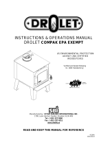
ASSEMBLING THE STOVE
Note: This section applies to models Compak, ML, RC and Nordic only.
1- Mount the 4 legs using 2 screws per leg.
2- Mount the ash lip with two screws.
3- Install the heat shield between the front legs,
just above the leg supports.
4- Bend the heat shield slightly to make it fit
between the back legs.

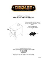
5
INSTALLING THE FIREBRICKS
Note: This section applies to models Compak, ML, RC and Nordic only.

6
INSTALLATION OF YOUR DROLET WOOD STOVE
POSITIONING THE STOVE
It is very important to position the wood stove as close as possible to the chimney, and in an area that will
favor the most efficient heat distribution possible throughout the house. The stove must therefore be
installed in the room where the most time is spent, and in the most spacious room possible. Recall that wood
stoves produce radiating heat, the heat we feel when we are close to a wood stove. A wood stove also
functions by convection, that is through the displacement of hot air accelerated upwards and its replacement
with cooler air. If necessary, the hot air distribution from the stove may be facilitated by a blower or the
installation of floor or wall grids. It is strictly forbidden to install your wood stove in a mobile home.
Important:
A wood stove must never be installed in a hallway or near a staircase, since it may block the way in case of
fire or fail to respect required clearance. The wood stove must not be hooked up to a hot air distribution
system since an excessive accumulation of heat may occur.
FLOOR PROTECTION
Your woodstove should be placed on a non-combustible surface. Having these minimum specifications.
FLOOR PROTECTION
Models
Thickness of
Sheet
Front Protrusion
Side Protrusions
Rear Protrusion
Baron 2000sp
1/4" (6mm)
18" (457mm)
8" (203mm)
10" (152mm)
Classic
1/4" (6mm)
18" (457mm)
8" (203mm)
8" (203mm)
Compak
1/4" (6mm)
18" (457mm)
8" (203mm)
8" (203mm)
Contempro 1600
1/4" (6mm)
18" (457mm)
8" (203mm)
8" (203mm)
Contempro 2000
1/4" (6mm)
18" (457mm)
8" (203mm)
8" (203mm)
Gemini 1200
1/4" (6mm)
18" (457mm)
6" (152mm)
6" (152mm)
Gemini 1500
1/4" (6mm)
18" (457mm)
6" (152mm)
6" (152mm)
ML
1/4" (6mm)
18" (457mm)
6" (152mm)
6" (152mm)
RC
1/4" (6mm)
18" (457mm)
8" (203mm)
8" (203mm)
Nordic
1/4" (6mm)
18" (457mm)
8" (203mm)
8" (203mm)
Sawman
1/4" (6mm)
18" (457mm)
10" (254mm)
10" (254mm)
Sawyer
1/4" (6mm)
18" (457mm)
8" (203mm)
10" (254mm)
Whistler , DLX
1/4" (6mm)
18" (457mm)
6" (152mm)
6" (152mm)

7
CLEARANCES TO COMBUSTIBLE MATERIALS
It is of utmost importance that the clearances to combustible material mentioned on your wood stove
certification plate be scrupulously respected upon installation.
CLEARANCES
Model
Back Wall
Side Walls
Corners
* Height
Baron 2000sp
18" / 381 mm
28" / 673 mm
16" / 406 mm
7' / 2,13 m
Baron 2000sp
with envelope
15" / 381 mm
26,5’’ / 673mm
26,5’’ / 673mm
7' / 2,13 m
Compak
16" / 406 mm
16" / 406 mm
16" / 406 mm
7' / 2,13 m
Contempro 1600
12" / 305 mm
24" / 610 mm
15" / 381 mm
7' / 2,13 m
Contempro 2000
12" / 305 mm
24" / 610 mm
15" / 381 mm
7' / 2,13 m
Gemini 1200
16" / 406 mm
16" / 406 mm
16" / 406 mm
7' / 2,13 m
Gemini 1500
16" / 406 mm
16" / 406 mm
16" / 406 mm
7' / 2,13 m
ML
16" / 406 mm
16" / 406 mm
16" / 406 mm
7' / 2,13 m
RC
16" / 406 mm
16" / 406 mm
16" / 406 mm
7' / 2,13 m
Nordic
16" / 406 mm
16" / 406 mm
16" / 406 mm
7' / 2,13 m
Sawman
16" / 406 mm
30" / 762 mm
30" / 762 mm
7' / 2,13 m
Whistler, DLX
16" / 406 mm
16" / 406 mm
16" / 406 mm
7' / 2,13 m
Single Pipe / Double
Pipe
Single Pipe / Double
Pipe
Single Pipe / Double
Pipe
Classic
16" (406mm) / 12" (305mm)
22" (559mm) / 22" (559mm)
11" (279mm) / 11" (279mm)
7' / 2,13 m
* Height, from stove base to ceiling.
You may decrease these clearances by installing heat radiation shields between the walls or the ceiling and
the stove. These heat radiation shields must be installed permanently, and can include sheet metal, a rigid
non-combustible sheet or a masonry wall. The installation standards of such heat radiation shields are listed
on the following page.
IT IS STRICTLY FORBIDDEN TO PLACE WOOD WITHIN THE MINIMUM CLEARANCES.

8
REDUCED CLEARANCES
You may decrease the clearances by installing heat radiation shields between the walls or the
ceiling and the stove. These heat radiation shields must be installed permanently, and can
include sheet metal, a rigid non-combustible sheet or a masonry wall.
Clearances of not less than 1" (25 mm) and not more than 3" (76 mm) between the bottom of the
shield and the floor and not less than 3" (76 mm) between the top of the shield and the ceiling
must be respected to allow vertical air circulation behind the shield. The shield must extend 20"
(500 mm) above the stove top and 18" (450mm) to each side of the stove (see Graphic 1).
Following the installation of such a heat radiation shield, the clearances mentioned on the stove
certification plate may be reduced as stated in the following table.
TYPE OF PROTECTION
Reducing Clearances With
Shielding
Sides and
Rear/Back
Top
Sheet metal, a minimum of 0,024" (0,61mm) spaced out at
least 1" (25mm) by non-combustible spacers (see graphic
2).
67%
50%
Ceramic tiles, or an equivalent non-combustible material on
fire-proof supports spaced out at least 1" (25 mm) by non-
combustible spacers (see graphic 3).
50%
33%
Ceramic tiles, or an equivalent non-combustible material on
fire-proof supports with a minimum of 0,024" (0,61 mm)
sheet metal backing spaced out at least 1" (25 mm) by non-
combustible spacers (see graphic 4)
67%
50%
Brick spaced out at least 1" (25 mm) by non-combustible
spacers (see graphic 5)
50%
N/A
Brick with a minimum of 0,024" (0,61 mm) sheet metal
backing spaced out at least 1" (25 mm) by non-combustible
spacers (see graphic 6).
67%
N/A

9
Graphic 1
A- Clearance to combustible material with no protection.
B- 500 mm (20 po.) minimum;
C- 25 mm (1 po.) minimum;
D- Between 25 mm (1 po.) and 75 mm (3 po.) ;
E- 75 mm (3 po.) minimum;
F- 450 mm (18 po.) minimum.
1- Wall shielding;
2- Non-combustible spacers;
3- Ceiling shielding;
4- Combustible wall;
5- Ceiling;
6- Heater (side view);
7- Heater (top view).

10
Graphic 2
A- 25 mm (1 po.) minimum;
1- Combustible wall;
2- Non-combustible spacer;
3- 0.61 mm (0.024") sheet metal.
Graphic 3
A- 25 mm (1 po.) minimum;
1- Combustible wall;
2- Non-combustible spacer;
3- Fire-proof support;
4- Ceramic tile or equivalent non-combustible material.
_____________________________________________________________________________
Graphic 4
A- 25 mm (1 po.) minimum;
1- Combustible wall;
2- Non-combustible spacer;
3- 0.61 mm (0.024") sheet metal;
4- Fire-proof support;
5- Ceramic tile or equivalent non-combustible material.

11
Graphic 5
A- 25 mm (1 po.) minimum;
1- Combustible wall;
2- Non-combustible spacer;
3- Brick.
Graphic 6
A- 25 mm (1 po.) minimum;
1- Combustible wall;
2- Non-combustible spacer;
3- 0.61 mm (0.024") sheet metal;
4- Brick
FOR BARON 2000SP USING THE ENVELOPE
It is strictly forbidden to connect the envelope to existing liners or existing floor registers
or grilles.

12
CHIMNEY
Your wood stove may be hooked up with a prefabricated or masonry chimney. If you are using a prefab
chimney, it must comply with S-629 standards; therefore it must be approved for up to 2100
o
F (650 C). It is
extremely important that it be installed according to the manufacturer's specifications.
If you are using a masonry chimney, it is important that it be built in compliance with the specifications of the
National Building Code. It must be lined with refractory bricks, metal or clay tiles sealed together with fire
cement. (Round flues are the most efficient).
The interior diameter of the chimney flue must be identical to that of the stove smoke exhaust. A flue which
is too small may cause draft problems, while a large flue favors rapid cooling of the gas, thus enhancing
creosote build-up and the risk of chimney fires. Current practice requires that the area of the chimney flue do
not exceed the stove exhaust area by more than 35%. For a round pipe, 35% of the area represents
approximately 1” (25 mm) on the diameter. (Ex: For a stove with an exhaust of 6”, the chimney flue should
not exceed 7” of diameter.) Note that it is the chimney and not the stove which creates the draft effect; your
stove's performance is directly dependent on an adequate draft from your chimney.
The following recommendations may be useful for the installation of your chimney:
1) It must rise above the roof at least 3' (0,9 m) from the uppermost point of contact.
2) The chimney must exceed any part of the building or other obstruction within a 10' (3,04 m) distance
by a height of 2' (0,60 m).
3) Installation of an interior chimney is always preferable to an exterior chimney. Indeed, the interior
chimney will by definition be hotter than an exterior chimney, being heated up by the ambient air in
the house. Therefore the gases which circulate will cool more slowly thus reducing the build-up of
creosote and the risk of chimney fires.
The draft, which is created by the tendency for hot air to rise, will be better with an interior chimney.
4) You must not install more than one heating unit per chimney flue.
5) The use of a fire-screen at the extremity of the chimney requires regular inspection in order to
insure that it is not obstructed.
STEP BY STEP INSTALLATION OF YOUR CHIMNEY
Note: The way to install your chimney may vary from one chimney manufacturer to another. The instructions
contained in this manual are based on the recommendations of chimney manufacturers whose products are
sold at many Canadian retailers of wood stoves and related heating accessories.
WALL SUPPORT SYSTEM
If your chimney must rise along an outside wall, you need to connect it to your stove through an adjacent wall.
For this type of installation, the following items are normally required:
Chimney
Suitable lengths of chimney (enough to go up to your roof)
An adjustable wall support
A wall thimble
An adequate number of wall bands (one for every 8 feet of chimney, excluding the roof portion)
A stove pipe adapter
One insulated tee & plug
A chimney cap.
Roof guys (if required)

13
Stove pipe
An adequate number of stove pipe sections.
A 90
o
elbow
1- Start by positioning your stove where you would like it to go, taking into account the minimum
clearances to combustible material. You will then be able to determine where the chimney will pass
through the wall. You will probably have to adjust the stove position slightly to ensure that your
chimney will run between the studs. You can use a stud finder to locate the studs. Use a spoke saw
or jig saw to cut a hole, remembering that you need to maintain a clearance of 2 inches between the
chimney and any combustible materials. For concrete walls, cut a hole slightly larger than the outer
diameter of the chimney.
2- Once the opening completed, you need to frame in the area to allow for the installation of a wall
thimble. A wall thimble is not required for installations through concrete walls.
3- You must first secure the wall thimble into the exterior wall surface. Then, do the same inside and
fasten the trim plate.
4- Then, from outside the building, slide a short chimney length (attached to the tee) through the wall
thimble. The chimney must extend at least 3 inches into the living space where it attaches to the
stove pipe.

14
5- You can now install the wall support. Simply slide the wall support up to the tee, ensuring that the
adapter on the support engages with the female coupler on the bottom of the tee. When the wall
support is level and properly positioned, you can use lag bolts to secure it into the wall studs. TO
complete the installation, install an insulated tee plug below the wall support.
6- You can start to add chimney sections. We recommend that you also use locking bands to secure all
connections. You will need to secure the chimney to the house using wall bands. Wall bands wrap
around the chimney and then attach to the wall. Install the first one 3 feet above the wall support.
Then, you will need another band for each 8 feet of chimney. Note: if your chimney must be
installed through your soffit, install a roof flashing above and finishing plate below where the
roof is cut. Consult the following section called “CEILING SUPPORT SYSTEM” for more
details.
7- Authorities require that the chimney extend not less than 3 feet above the highest point where it
passes through the roof of a building and not less than 2 feet above any portion of the building within
10 feet. If the chimney extends more than 5 feet above the roof deck, roof guys with telescoping
legs and draw bands are required.

15
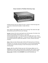
8- Finally, twist on your rain cap and you can head back inside.
9- You are now ready to connect your chimney to your stove. Simply install the inter-connecting stove
pipe between the stove pipe adapter and the stove. You can follow the instructions in the following
sections of this manual under « COUPLINGS ».
CEILING SUPPORT SYSTEM
If your chimney must rise inside the house and go through the ceiling, you need to connect it to your stove at
the ceiling level. For this type of installation, the following items are normally required:
Chimney
An adequate number of chimney sections (enough to go up to your roof)
A ceiling support kit with stove pipe adapter
An attic insulation shield
A roof flashing kit
A chimney cap
Roof guys (if necessary)
Stove pipe
Suitable lengths of stove pipe

16
1- Place your stove where you would like it located and use a plumb line to mark the ceiling directly
above your stove flue. You will probably have to adjust this position slightly to ensure that your
chimney will run between the joists. You can use a stud finder to locate the joists. You also need to
take into account the minimum clearances to combustible materials. After you have determined
where the chimney will go through the ceiling, use a spoke saw or power jig saw to cut a hole,
remembering that you need a minimum 2-inch clearance between the chimney and any combustible
materials. Depending on whether you have a one or two story structure, you will need to cut a
matching hole through the floor of the attic or second floor living space.
2- Before you install the ceiling support, you need to frame the area.
3- To install the ceiling support, just slide the assembly into the framed opening from below. Once you
ensure that the finishing plate is flush with the underside of the ceiling and assembly is level, secure
it with screws.
4- Once the support is secure, you can begin to assemble the chimney by lowering the first section into
the support. Make sure that the male coupler is pointing upwards, as indicated by the arrow on the
chimney label.

17
5- Then, from beneath the support, insert the stove pipe adapter and twist-lock it into place.
6- Now, you can add additional chimney sections. Continue adding chimney lengths until a height of
about 2 feet below the next ceiling level. An attic insulation shield must be installed where a chimney
passes from a lower living space into an upper living space or attic space. It is designed to keep
insulation materials away from the chimney. A second attic insulation shield must be installed if your
chimney passes from a lower living space into an upper living space. As wee, you must enclose all
sections of the chimney where is passes through a living space. Elbows (15
o
or 30
o)
are used when
you need to offset your chimney to clear an obstruction or to avoid having to cut joists.
7- Once you have cut through your roof and framed the joists, it is time to work outdoors. Authorities
require that the chimney extend not less than 3 feet above the highest point where it passes through
the roof of a building and not less that 2 feet above any portion of the building within 10 feet. You will
need to install a roof flashing. The roof flashing slides over your chimney pipe and goes under your
shingles. Once you have done that, check that everything is plumb, and nail the flashing into the roof
deck. Seal the joint between the shingles and the plate with silicone.

18
8- Next, slide the storm collar down the chimney until it contacts the flashing. Tighten the nut and bolt
and seal the collar to the chimney with a waterproof, non-combustible silicone sealant. Finally, twist
on your rain cap and you can head back inside. If the chimney extends more than 5 feet above the
roof deck, roof guys with telescoping legs and draw bands are required.
9- You are now ready to connect your chimney to your stove. Simply install the inter-connecting stove
pipe between the stove pipe adapter and the stove. You can follow the instructions in the following
sections of this manual under “COUPLINGS”.

19
COUPLINGS
It is very important to measure the clearance between your connectors (commonly called stove pipe) and the
surrounding combustible surfaces. If the normal 18 inches clearance required cannot be obtained, you may
have to use an insulated flue pipe in order to install. You must read the flue pipe manufacturer's instructions
before installation.
Your connectors and chimney must have the same diameter as the stove outlet. If this is not the case, we
recommend you contact your supplier in order to insure there will be no problem with the draft. Your
connectors should be made of aluminized or ordinary steel with a minimum 24 gauge thickness.
Your smoke exhaust system (connectors) should be assembled in such a way that the male section of the
pipes faces down. Attach each of the sections to one another with three equidistant metal screws.
The connectors must be short and straight. All sections installed horizontally must slope at least 1/4 inch per
foot, with the upper end of the section toward the chimney.
To insure a good draft, the total length of the exhaust system should never exceed 8 to 10 feet. (Except for
cases of vertical installations or cathedral-roof, where the smoke exhaust system can be much longer and
connected without problem to the chimney at the ceiling level). There should never be more than one 90
elbow in the smoke exhaust system.
Installation of a "barometric draft stabilizer" (fireplace register) on a smoke exhaust system is not
recommended.
Furthermore, installation of a draught damper is forbidden. Indeed, with a controlled combustion wood stove,
the draught is regulated upon intake of the combustion air in the stove and not at the exhaust.
The connectors must not go through a ceiling, a storage area, a floor, or any other combustible partition.

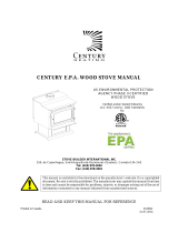
20
Avoid 90 degree eblows
We recommend that you use
two 45 degree elbows instead
/