Page is loading ...

XCite™ Advanced Programming & Configuration
XCite Product Family
Modes of Operation
Radio Modem Configuration
Advanced Networking & Security
Appendices
Advanced Manual v1.1
Advanced Development for the XCite Product Family
Products Supported: XCite OEM RF Modules (900 MHz)
XCite RS-232/485 and USB RF Modems
355 South 520 West, Suite 180
Lindon, UT 84042
Phone: (801) 765-9885
Fax: (801) 765-9895
M100045
2005.08.02
www.maxstream.net

XCiteAdvancedProgramming&Configuration–AdvancedManualv1.1
© 2005 MaxStream, Inc. All rights reserved
Nopartofthecontentsofthismanualmaybetransmittedor
reproducedinanyformorbyanymeanswithoutthewritten
permissionofMaxStream,Inc.
XCite™isatrademarkofMaxStream,Inc.
TechnicalSupport
Phone:(801)765‐9885
LiveChat:
www.maxstream.net
E‐Mail:
rf‐[email protected]
©2005MaxStream,Inc.,ConfidentialandProprietary
ii

XCiteAdvancedProgramming&Configuration–AdvancedManualv1.1
Contents
XCite Product Family 5
Introduction 5
Pin Signals 6
I/O Pin Signals 8
Flow Control Pin Signals 9
Remaining Pin Signals 10
Interfacing Hardware 11
XCite Development Kit (RS-232/485) 11
MaxStream RS-232/485 Interface Board (Part Number: XIB-R) 11
RS-232/485 Interface Board Components & Features 12
Adapters 13
Antennas 15
Modes of Operation 16
Idle Mode 16
Transmit Mode 17
Cyclic Redundancy Check (CRC) 17
Transmission Latency 17
Receive Mode 18
Sleep Modes 19
Pin Sleep (SM = 1) 19
Serial Port Sleep (SM = 2) 20
Cyclic Sleep (SM = 3-8) 20
Cyclic Scanning 21
AT Command Mode 22
AT Command Mode Protocol 22
Configuration Software 24
X-CTU Software 24
Serial Communications Software (for AT Commands Only) 24
Radio Modem Configuration 25
Command & Parameter Types 25
AT Commands 25
Non-AT Settable Parameters 25
XCite Command & Parameter Reference 26
Individual Command & Parameter Descriptions 27
Advanced Networking and Security 37
Network Layers 37
Vendor Identification Number (ATID) 38
Channel (ATHP) 38
Destination Address (ATDT) and Address Mask (ATMK) 38
©2005MaxStream,Inc.,ConfidentialandProprietary
iii

XCiteAdvancedProgramming&Configuration–AdvancedManualv1.1
Appendix A: FCC Certifications 41
FCC Compliance 41
OEM Labeling Requirements 41
FCC Notices 42
9XCite (900 MHz) Approved Antennas 43
Appendix B: Additional Information 44
XCite OEM RF Module Specifications 44
1-Year Warranty 45
XCite OEM RF Module Part Numbers 45
Appendix C: Troubleshooting & FAQs 46
Contact MaxStream 46
©2005MaxStream,Inc.,ConfidentialandProprietary
iv

XCiteAdvancedProgramming&Configuration–AdvancedManualv1.1
©2005MaxStream,Inc.,ConfidentialandProprietary
5
XCiteProductFamily
Introduction
The XCite Radio Modem is a drop-in wireless solution that can add RF connectivity to any data
system. XCite Radio Modems transfer a standard asynchronous serial data stream and feature
the following:
• Continuous data stream of up to 38400 bps (factory-set, RF data rate)
• Serial Interfacing from 1200 to 115200 bps
• Software selectable between Hopping (FHSS) and Single Frequency Channel Modes
• Approved by the FCC under Part 15 of the FCC Rules and Regulations
• Variable input supply voltage (2.85 – 5.50 VDC)
This advanced manual provides information on how to operate and configure XCite Radio Modems
to accommodate a wide range of design criteria. Modems can be configured to activate advanced
functionality in networking, serial interfacing, sleep (low power) modes and diagnostics.
Features:
Long Range
• Indoor/Urban Range: Up to 300’ (90 m)
• Outdoor/RF Line-of-sight Range: Up to 1000’ (300 m)
• Receiver Sensitivity: -108 dBm (9600 Baud), -104 dBm (38400 Baud)
Low Power
• Transmit Power Output: 4 mW [50 mW effective considering receiver sensitivity]
• 55 mA transmit / 45 mA receive current consumption
• Power-down current as low as 20 µA
Advanced Networking & Security
Specifications [
Appendix B]
1-Year Warranty [
Appendix B]
Free & Unlimited Technical Support [
Appendix C]
Worldwide Acceptance
FCC Approved (USA) [Go to Appendix A for FCC Requirements]
Devices that embed XCite Radio Modems can inherit MaxStream’s FCC certification
IC (Industry Canada) Certified
ISM (Industrial, Scientific & Medical) frequency band
MaxStream products manufactured under ISO 9001:2000 registered standards

XCiteAdvancedProgramming&Configuration–AdvancedManualv1.1
©2005MaxStream,Inc.,ConfidentialandProprietary
6
Pin Signals
The interface signals are available through an 11-pin header. All pins operate on 2.85-5.50V
CMOS levels. The following five J1 pin signals are most commonly used in data radio systems:
• DI (pin 4 – Data In)
• DO (pin 3 – Data Out)
• VCC (pin 10 – Power)
• GND (pin 11 – Ground)
• DO2-
(pin 1 – Clear-to-Send)
Application Circuit
Figure1. ApplicationCircuit–connectiontohostprocessor
Table1. J1PinDescriptions–XCiteOEMRFModulepinsignalsandtheirfunctions
(Low‐assertedsignalsdistinguishedwithahorizontallineoversignalname)
Module Pin Signal Name I/O When Active Description
1 DO2 O* low Clear-to-Send ( ) Flow Control
2 DI3 I* high
Can be used to enter Sleep Modes that
consume less power
3 DO (Data Out) O* n/a
Serial Data leaving the XCite Module
(to the host)
4 DI (Data In) I n/a
Serial data entering the XCite Module
(from the host)
5 DI2 I** low Request-to-Send ( )
6
I* low Reset Module Parameters
7 DO3 O high Receive (RX) LED
low - Asserted during transmission
8 / PWR O
high PWR – Indicates power is on
9
CONFIG
I*** low
Backup method for entering AT Command
Mode. Primary method is with “+++” [See
CC
Parameter]
10 VCC I - 2.85 – 5.50 VDC Regulated
11 GND - - Ground
* Pinutilizes10KΩPull‐Upresistor(alreadyinstalledinthemodule)
** Pinutilizes10KΩPull‐Downresistor(alreadyinstalledinthemodule)
*** Pinutilizes100KΩPull‐Upresistor(alreadyinstalledinthemodule)
Note: When integrating the XCite Module onto a Host PC Board, all lines that are not used should
be left disconnected (floating).
Table2. J2PinDescriptions

XCiteAdvancedProgramming&Configuration–AdvancedManualv1.1
©2005MaxStream,Inc.,ConfidentialandProprietary
7
Module Pin Pin Name
1 Reserved
2 GND
3 GND
4 GND
J2 Pins are used primarily for mechanical
stability and may be left disconnected.

XCiteAdvancedProgramming&Configuration–AdvancedManualv1.1
©2005MaxStream,Inc.,ConfidentialandProprietary
8
I/O Pin Signals
} Pin 4: DI (Data In)
<Input> Data enters the XCite Module through the DI Pin as an asynchronous serial signal. The
signal should idle high when no data is being transmitted.
Each data packet consists of a start bit (low), 8 data bits (least significant bit first) and a stop bit
(high). The figure of a UART data packet [Figure 2] illustrates the serial bit pattern of data
shifting into the module. The start and stop bits from the UART signal are not transmitted, but
are regenerated on the receiving module.
Æ DI Buffer
Once serial data has entered the XCite Module through the DI Pin, the data is stored in the DI
Buffer until it can be transmitted.
Once the first byte of data enters the DI Buffer, the module begins to initialize the RF channel
unless RF data is already being received. In the case where the module is receiving RF data,
serial data is stored in the DI Buffer. When the DI Buffer is 17 bytes away from being full, the
XCite Module de-asserts (high)
to signal to the host device to stop sending data. re-
asserts once the DI Buffer has at least 35 bytes available.
In addition to
hardware flow control, XON/XOFF software flow control can also be
implemented [See the FL (Software Flow Control) Command]. In this case, the XCite Module
sends XON and XOFF signals in addition to asserting/de-asserting
.
Figure2. UARTdatapacket0x1F(decimalnumber“31”)astransmittedthroughtheXCiteModule
Data is packetized for transmission. The packet structure is as follows:
Figure3. RFPacketStructure
} Pin 3: DO (Data Out)
<Output> Data from RF (over-the-air) transmission is received through the DO Pin. Received
data is checked for errors and addressing, then sent to the DO Buffer before being sent to the
host device. This pin utilizes a 10K Ω Pull-Up resistor that is already installed in the module.
DO Buffer Æ
Once incoming RF data is received into the DO Buffer, data is sent out the serial port to a host
device. If
is enabled for flow control, data will not be sent out the DO Buffer as long as the
pin is de-asserted (high). In such a scenario, data could be lost if is de-asserted long
enough to allow the DO Buffer to become full. Pins 1 & 2 can also be used for flow control.

XCiteAdvancedProgramming&Configuration–AdvancedManualv1.1
©2005MaxStream,Inc.,ConfidentialandProprietary
9
Flow Control Pin Signals
} Pin 1: DO2- (Clear-to-Send)
<Output> The pin (Clear-to-Send) informs the host device whether or not serial data can be
sent to the XCite Module from the host device. When Pin 1 is asserted (low), serial data is
permitted to be sent to the XCite Module. In RS-232 applications, Pin 1 is directly associated with
the DI Buffer. In RS-485/422 applications, the Pin 1 signal controls the transmit driver (TX
enable) on the RS-485 and RS-422 logic converters (on the MaxStream Interface Board or
equivalent). Pin 3 utilizes a 10KΩ Pull-Up resistor that is already installed in the module. In some
applications, Pin 1 may not need to be observed.
Hardware Flow Control
If the DI Buffer reaches its capacity, either the
line or XON / XOFF flow control must be
observed to prevent loss of data between the host device and the XCite Module. There are two
cases in which the DI Buffer may become full:
1. If the serial interface rate is set higher than the default baud rate for the module, the
module will receive serial data faster than it is transmitted.
2. If the XCite Module is receiving a continuous stream of data or if it is monitoring data on a
network, any serial data that arrives on the DI pin is placed in the DI Buffer. This data will
be transmitted when the module no longer detects RF data in the network.
XON Software Flow Control
XON/XOFF software flow control can be used (on Pin 3) instead of
hardware flow control.
[See FL (Software Flow Control) Command for more information]
} Pin 5: DI2- (Request-to-Send)
<Input> The Pin 5 ( ) signal can be configured to enable flow control recognition. Use RT
Command to adjust the parameters that control Pin 5 flow control. By default,
flow control is
not observed. This pin utilizes a 10KΩ Pull-Down resistor already installed in the module.
Hardware Flow Control
If
flow control is enabled, no data is sent out the DO pin when is de-asserted (high). If
flow control is implemented on the host device, RT Parameter must be set on the XCite
Module in order to recognize the
signal as a flow control line.
If
is asserted (low), all received RF data is placed in the DO Buffer until the line is de-
asserted. Once the DO Buffer reaches capacity, any additional received RF data is lost.
XOFF Software Flow Control
XON/XOFF software flow control can be used (on Pin 4) to simulate
hardware flow control.
[See FL (Software Flow Control) Command for more information]

XCiteAdvancedProgramming&Configuration–AdvancedManualv1.1
©2005MaxStream,Inc.,ConfidentialandProprietary
10
Remaining Pin Signals
} Pin 2: DI3-Sleep/Power-Down
<Input> Pin 2 can be used to transition the XCite Module into a low power-consuming Sleep
Mode. If SM = 1 [SM (Sleep Mode) Command], allowing Pin 2 to float high causes the module to
enter into a state of minimal power-consumption (until awakened by driving Pin 2 low). [Go to
the “
Sleep Modes” section for more information.] This pin utilizes a 10K Ω Pull-Up resistor already
installed in the module.
} Pin 6:
<Input> Pin 6 is almost always high and only low when the radio is reset. Since the OEM module
has an onboard reset monitor, this pin can be left disconnected. Pin 6 utilizes a 10KΩ Pull-Up
resistor already installed in the module.
} Pin 7: DO3-RX LED
<Output> Pin 7 is normally driven low, but is driven high briefly by the radio to indicate RF data
reception. This pin can be tied through a resistor to an LED for visual indication.
} Pin 8: / PWR
<Output> Pin 8 is normally driven high and can be tied through a resistor to an LED to indicate
the following:
• The module has power
• The module is not is sleep mode
• Pin 8 pulses on/off when data is transmitted over-the-air.
} Pin 9:
<Input> When Command Mode cannot be entered using normal procedure [See “Command
Mode” section], the
pin is used to manually enter the module into Command Mode. If
Pin 9 is asserted during reset or power-up, the module immediately enters into Command Mode
at the module’s default baud rate. After the pin is asserted, the serial port baud rate is
temporarily set to match the default baud rate of the XCite Module in use. Upon entering into
Command Mode, all configured parameters (including baud rate) remain in their saved state
unless modified as is described in the “Module Configurations” chapter of this manual. This pin
utilizes a 100K Ω Pull-Up resistor already installed in the module.
IMPORTANT: The
pin is intended as a secondary method for entering Command Mode.
The primary method is with a command break sequence. MaxStream reserves the right to change
the functionality of the
pin and recommends using the command break sequence [See
“Command Mode” section] for entering Command Mode.
} Pin 10: VCC (power)
<Input> Pin 10 accepts regulated 5V signals.
} Pin 11: GND (Ground)
Pin 11 is used for grounding.

XCiteAdvancedProgramming&Configuration–AdvancedManualv1.1
©2005MaxStream,Inc.,ConfidentialandProprietary
11
Interfacing Hardware
MaxStream, Inc. developed proprietary interface boards (MaxStream Product numbers: XIB-R for
RS-232/485 interfacing) to facilitate the connection between XCite Radio Modems and serial
devices. Many integrators develop their own interfacing circuitry; others use MaxStream’s
Interface Boards. In either case, the following sections illustrate how to interface with XCite OEM
RF Modules by illustrating properties of the MaxStream XIB-R Interface Board.
XCite Development Kit (RS-232/485)
The MaxStream Interface board is included with the XCite Development Kit. The kit includes all
the hardware and software needed for basic wireless connections.
Table3. XCiteDevelopmentKitcontents
Item Qty. Description Part Number
Quick Start Guide 1
Quickly familiarize users with some of the XCite Module’s most
important functions. The guide provides step-by-step
instructions on how to make an RF link and test its ability to
transport data over varying ranges and conditions.
MD0009
CD 1 CD includes documentation and configuration software M100105
XCite Module
(w/ RPSMA antenna port)
1
Module comes with fixed RF Data (baud) rates up to 38400
bps
XC09 - (…) NSC
XCite Module
(w/ attached wire antenna)
1
Module comes with fixed RF Data (baud) rates up to 38400
bps
XC09 - (…) WNC
MaxStream Interface Board 2
Supplies regulated 5V DC power to module and provides
signal-level conversion for interfacing with PC RS-232 serial
ports or RS-485/422 devices
XIB-R
RPSMA Antenna 1 RPSMA half-wave dipole antenna A09-HASM-675
Serial Loopback Adapter 1
Connects to the female RS-232 (DB-9) serial connector of the
XCite Module and can be used to configure the radio modem
to function as a repeater (for range testing)
JD2D3-CDL-A
NULL Modem Adapter
(male-to-male)
1
Connects to the female RS-232 (DB-9) serial connector of the
XCite Module and can be used to connect the radio modem to
another DCE (female DB9) device
JD2D2-CDN-A
NULL Modem Adapter
(female-to-female)
1
Used to bypass radios to verify serial cabling is functioning
properly
JD3D3-CDN-A
Male DB-9 to RJ-45 Adapter 1
Facilitates adapting the DB-9 Connector to a CAT5 cable
(female RJ45 to male DB9)
JE1D2-CDA-A
Female DB-9 to RJ-45 Adapter 1
Facilitates adapting the DB-9 Connector to a CAT5 cable
(female RJ45 to female DB9)
JE1D3-CDA-A
9V AC Power Adapter 2 Wall-based transformer with US 2-prong plug JP4P2-9V4-6F
9V Battery Clip 1 Allows Interface Board to be remotely powered by a 9V battery JP2P3-C2C-4I
RS-232 Cable (6’) 2
Straight-through serial cable that connects interface board
(DCE) to a PC (DTE)
JD2D3-CDS-6F
MaxStream RS-232/485 Interface Board (Part Number: XIB-R)
The MaxStream Interface board was developed to provide a means of connecting the XCite
Module to any system having an RS-232 or RS-485/422 connection. Since the XCite Module
requires signals to enter at CMOS voltages, one of the main functions of the interface board is to
convert interface signals from CMOS levels (2.85 – 5.50V) to RS-232 levels (-12 - +12V). The
MaxStream Interface Board includes the following built-in features:
• DIP Switch
• Configuration Switch
• Power Switch
• LEDs
• DB-9 Connector
• Power Connector

XCiteAdvancedProgramming&Configuration–AdvancedManualv1.1
©2005MaxStream,Inc.,ConfidentialandProprietary
12
RS-232/485 Interface Board Components & Features
4a. Power Switch
Figure4. FrontView
4b. LEDs
The LED indicators visualize diagnostic status information. The
radio modem’s status is represented as follows:
Move the Power Switch to the on (up) position to power the
Interface Board. DIP Switch [5a] settings are only read during
a power-up sequence.
• Yellow (top LED) = Serial Data Out (to host)
• Green (middle) = Serial Data In (from host)
• Red (bottom) = Power/TX Indicator (Red light is on when
powered, off briefly during RF transmission)
4c. Serial Port
Standard female DB-9 (RS-232) DCE connector – This connector
can be also used for RS-485 and RS-422 connections.
4d. Power Connector
7-18 VDC Power Connector (Center positive, 5.5/2.1mm) – Power
can also be supplied through Pin 9 of the DB-9 Connector.
5a. DIP Switch
Figure5. BackView
5b. Configuration Switch
The Configuration Switch provides an alternate way to enter “AT
Command Mode”. To enter “AT Command Mode” at the radio
modem’s default baud rate, hold the Configuration Switch down
while powering on the module using the Power Switch.
The DIP Switch configures the XCite OEM RF Module to
operate in different modes. DIP Switch settings are only read
and applied during a powering-on sequence. [See Figure
below for DIP Switch settings]
5a. DIP
Switch
5b. Configuration
Switch
O
N
123456
Figure6. MaxStreamXIB‐R(RS‐232/485)InterfaceBoardDIPSwitchSettings
*The“(RestoreDefaults)”
setting,forswitches1&2,can
beusedtorestoreATSettable
parameterstotheirdefault
states.Onceswitchesarein
position,resetoccursduring
nextpower‐up.

XCiteAdvancedProgramming&Configuration–AdvancedManualv1.1
©2005MaxStream,Inc.,ConfidentialandProprietary
13
Adapters
The MaxStream Development Kit comes with several adapters. The connectors and adapters
facilitate basic functions, such as the following:
• Performing Range Tests
• Testing Cables
• Connecting to other RS-232 DCE or DTE devices
• Connecting to terminal blocks or RJ-45 for RS-485/422 devices
NULL Modem Adapter (male-to-male)
Part Number: JD2D2-CDN-A (Black, DB-9 M-M) The male-to-male NULL modem adapter can
be used to connect two DCE devices. A DCE device is one that connects with a straight-through
cable to the male serial port of a computer (DTE).
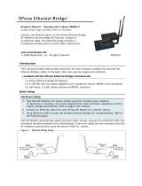
Figure 7. Male NULL modem adapter and pinouts
NULL Modem Adapter (female-to-female)
Part Number: JD3D3-CDN-A (Gray, DB-9 F-F) The female-to-female NULL modem adapter can
be used to verify serial cabling is functioning properly. To test cables, insert the female-to-female
NULL modem adapter in place of a pair of radio modems and test the connection without radio
modules in the connection.
Figure 8. Female NULL modem adapter and pinouts
Serial Loopback Adapter
Part Number: JD2D3-CDL-A (Red, DB-9 M-F) The serial loopback adapter is used for range
testing. During a range test, the serial loopback adapter configures the radio modem to function
as a repeater by looping serial data back into the radio for retransmission.
Figure 9. Serial loopback adapter and pinouts

XCiteAdvancedProgramming&Configuration–AdvancedManualv1.1
©2005MaxStream,Inc.,ConfidentialandProprietary
14
Male DB-9 to RJ-45 Adapter
Part Number: JE1D2-CDA-A (Yellow, RJ-45 female to DB-9 male) This adapter facilitates
adapting a DB-9 connector to a CAT5 cable.
Figure 10. Male RS‐485/422 Adapter and pin specifications
Female DB-9 to RJ-45 Adapter
Part Number: JE1D3-CDA-A (Green, RJ-45 female to DB-9 female) This adapter facilitates
adapting a DB-9 connector to a CAT5 cable.
Figure 11. Female RS‐485/422 Adapter and pin specifications
RS-485/422 Connection Guidelines
The RS-485/422 protocol provides a solution for wired communications that can tolerate high
noise and push signals over long distances. RS-485/422 signals can communicate as far as 4000
feet (1200 meters). RS-232 signals are only suitable for cable distances up to 100 feet (30.5
meters).
RS-485 offers multidrop capability in which up to 32 nodes can be connected. The RS-422
protocol is used for point-to-point communications.
Suggestions for integrating the XCite Module with the RS-485/422 protocol:
1. When using Ethernet twisted pair cabling: Select wires so that T+ and T- are connected to
each wire in a twisted pair. Likewise, select wires so that R+ and R- are connected to a
twisted pair. (For example, tie the green and white/green wires to T+ and T-.)
2. For straight-through Ethernet cable (not cross-over cable) – The following wiring pattern
works well: Pin 3 to T+, Pin 4 to R+, Pin 5 to R-, Pin 6 to T-
3. Note that the connecting cable only requires 4 wires (even though there are 8 wires).
4. When using phone cabling (RJ-11) – Pin 2 in the cable maps to Pin 3 on opposite end of
cable and Pin 1 maps to Pin 4 respectively.

XCiteAdvancedProgramming&Configuration–AdvancedManualv1.1
©2005MaxStream,Inc.,ConfidentialandProprietary
15
Antennas
[See Appendix A for a list of FCC-Approved Antennas]
Factors that determine the distance an RF link can transmit:
• Ambient RF noise (interference)
• Line-of-sight obstructions
• Transmit power
• Receive sensitivity
• Antenna configuration
Factors that affect antenna performance:
• RF cable length
• Height of antennas off the ground
• Obstructions
• Radiation pattern
• Antenna Gain
XCite Antenna Connector Options
In order to comply with the FCC rules and obtain a “modular” certification, it is required that the
XCite Modules utilize a “non standard” connector. This is to ensure that the radios are used only
with approved antennas. The XCite radio modules have two connector options:
• RPSMA
• N-Connector
RPSMA
The Reverse Polarity SMA (RPSMA) connector uses the same body as a
regular SMA connector. In order to be a “non standard” connector, the
gender of the center conductor is changed. A female RPSMA will actually
have a male center conductor.
N-Connector
An N-Connector does not come installed on the XCite Modules, but is a common connector used
with higher gain antennas. MaxStream can supply “RPSMA to N-Connector” cables in various
lengths.
Antenna Cables
RF cables are typically used to connect a radio installed in a cabinet to an antenna mounted
externally. As a general rule, it is best to keep the RF cable as short as possible. All cables have
losses which are usually measured in dB loss per 100 ft. MaxStream has cables available made
with LMR-195. Some common cables and dB losses are included in this table:
Table 4. Potential Signal Strength Loss due to Antenna Cable Length
Cable
Type
Loss at 900 MHz per 100’
(loss per 100m)
Loss at 2.4 GHz per 100’
(loss per 100m)
Diameter
Inches (mm)
RG-58 14.5 dB (47.4 dB) 25.3 dB (83.2 dB) 0.195” (5.0 mm)
RG-174 25.9 dB (85.0 dB) 44.4 dB (145.8 dB) 0.100” (2.5 mm)
RG-316 24.7 dB (81.0 dB) 42.4 dB (139.0 dB) 0.102” (2.6 mm)
LMR-195 11.1 dB (36.5 dB) 19.0 dB (62.4 dB) 0.195” (5.0 mm)
LMR-240 7.6 dB (24.8 dB) 12.9 dB (42.4 dB) 0.240” (6.1 mm)

XCiteAdvancedProgramming&Configuration–AdvancedManualv1.1
©2005MaxStream,Inc.,ConfidentialandProprietary
16
Modes of Operation
XCite Radio Modems operate in five modes. The modules operate in one mode at a time.
Figure 12. MaxStream Modes of Operation
Idle Mode
XCite Modules operate in Idle Mode when data is not being transmitted nor received. While in Idle
Mode, modules use the same amount of power as they do in RX (Receive) mode. Modules will
transition into other modes under any of the following conditions:
1. Serial data is received in the DI Buffer (Module then transitions into Transmit Mode)
2. Valid data is received by the antenna (Module then transitions into Receive Mode)
3. AT Command Mode Sequence is issued (Module then transitions into AT Command Mode)
4. Sleep Mode condition is met (Module then transitions into Sleep Mode)
Modules automatically transition back to Idle Mode once finished responding to these conditions.

XCiteAdvancedProgramming&Configuration–AdvancedManualv1.1
©2005MaxStream,Inc.,ConfidentialandProprietary
17
Transmit Mode
When the first byte of serial data comes through the DI Pin and arrives in the DI Buffer, the
module transitions into Transmit Mode. Once in Transmit Mode, the module initializes a
communications channel. During channel initialization, incoming serial data accumulates in the DI
buffer. After the channel is initialized, data in the DI buffer is grouped into packets (up to 64
bytes in each packet) and is transmitted. The module continues to transmit data packets until the
DI buffer is empty. Once transmission is finished, the module returns to Idle Mode. This
progression is shown below:
Figure 13. Transmission of data
Idle
Mode
De-Assert
TX/PWR
No Data in
DI Buffer
Data Received in
Data Buffer
Initialization Complete
RF OUT Buffer Empty
Remained Data
in DI Buffer
Collect Serial
Data in
Data Buffer
Begin
Initialization of
Communications
Channel
not complete
RF OUT Buffer
not empty
Send Data &
Assert TX/PWR
when < 17
bytes left
(A Block Diagram of the XCite Module is located in the “XCite OEM RF Module” Product Manual)
Cyclic Redundancy Check (CRC)
To verify data integrity and provide built-in error checking, a 16-bit cyclic redundancy check
(CRC) is computed for the transmitted data and attached to the end of each data packet before
transmission. On the receiving end, the receiver computes the CRC on all incoming data.
Received data that has an invalid CRC is discarded [See “Receive Mode” section on next page].
Transmission Latency
Transmission latency depends on the number of bytes contained in a packet and the baud rate of
the module. To reduce latency in the XCite Module, load in a single channel version using the X-
CTU Software. Operating in Single Frequency Channel Mode greatly reduces latency.

XCiteAdvancedProgramming&Configuration–AdvancedManualv1.1
©2005MaxStream,Inc.,ConfidentialandProprietary
18
Receive Mode
If a module detects RF transmitted data while operating in Idle Mode, it transitions into Receive
Mode to start receiving packets. Once a packet is received, it goes through the receiving-end of a
CRC (cyclic redundancy check) to ensure that the data was transmitted without error. If the CRC
data bits on the incoming packet are invalid, the packet is discarded. If the CRC is valid, the
packet is placed the DO Buffer. This process is shown in the figure below:
Figure 14. Receive Mode Data Flow
Valid Header
RX (Receive)
Data
Assert
RX/LED
Check
Module
Address
De-Assert
RX/LED,
Check CRC
Check
Channel
Number
Send Data to
Data Out
(DO) Buffer
Check
VID
Check for
More Data
Idle
Mode
Receive
Header
Data
Detected
Invalid CRC
VIDs
match
Channels
match
Addresses
match
Data
Detected
Invalid VID
Invalid
Channel
Invalid
Address
No Data
The module returns to Idle Mode after valid data is no longer detected or once an error is
detected in the received data. If serial data-to-transmit is stored in the DI buffer while the
module is giving precedence to Receive Mode, the data will be transmitted after the module
finishes receiving data and returns to Idle Mode.

XCiteAdvancedProgramming&Configuration–AdvancedManualv1.1
©2005MaxStream,Inc.,ConfidentialandProprietary
19
Sleep Modes
Sleep Modes enable the XCite Radio Modem to go into states of low power-consumption when not
in use. Any of three Sleep Modes configurations can be used:
1. Host Controlled
2. Wake on RF activity
3. Wake on Serial Port activity
To enter Sleep Mode, one of the following must occur (In addition to SM (Sleep Mode) Command
having a non-zero value):
• The radio modem must be idle (no data transmission or reception) for a user-defined
period of time [
See ST (Time before Sleep) Command]
• The Sleep Pin (Pin 2) is de-asserted
Once in Sleep Mode, the radio modem does not transmit or receive data until it first returns to
Idle Mode. The return into Idle Mode is triggered by the de-assertion of Pin 2 or the arrival of a
serial byte through Pin 4 (Data In). Sleep Mode is enabled and disabled using SM Command.
The following table lists MaxStream’s Sleep Mode configurations and the requirements needed to
transition into and out of Sleep Mode:
Table 5. Sleep Mode Configurations
Sleep Mode
Setting
Transition into Sleep
Mode
Transition out of
Sleep Mode
Related
Commands
Power
Consumption
Pin Sleep
(SM=1)
Microcontroller can shut down
and Wake-up modules. Assert
igh) Sleep Pin (Pin 2). (h
Note: Module will complete a
transmission or reception
before activating Pin Sleep.
De-Assert (low) Sleep
pin (Pin 2)
SM 20 µA
Serial Port Sleep
(SM=2)
Automatic transition into Sleep
Mode after user-defined
period of inactivity (no
transmitting or receiving).
Period of inactivity set using
ST Command.
When serial byte is
received on the DI pin
(Pin 4)
SM, ST 1 mA
Cyclic Sleep
(SM=3-8)
Transitions into and out of Sleep Mode in cycles (user-
selectable wake-up interval of time (½ second to 16
seconds) set by SM Command). The Cyclic Sleep
interval time must be shorter than “Wake-up Initializer
imer” (set by LH Command). T
(Can be forced into Idle Mode using Sleep Pin if PW (Pin
Wake-up) Command is issued.)
HT, LH, PW, SM, ST
typically 76 µA
(when sleeping)
Pin Sleep (SM = 1)
<Lowest Power Configuration> In order to achieve this low-power state, Pin 2 must be asserted
(high). The module remains in Pin Sleep until the Sleep pin is de-asserted. The module will
complete a transmission or reception before activating Pin Sleep.
After enabling Pin Sleep (SM (Sleep Mode) Parameter = 1), Pin 2 controls whether the XCite
Module is active or in Sleep Mode. When Pin 2 is asserted (high), the module transitions to Sleep
Mode and remains in its lowest power-consuming state until the Sleep pin is de-asserted. The
XCite Module requires 40ms to transition from Sleep Mode to Idle Mode. Pin 2 is only active if the
module is setup to operate in this mode; otherwise the pin is ignored. Once in Pin Sleep Mode,
Pin 1 (
) is de-asserted (high), indicating that data should not be sent to the module. Pin 8
(PWR) is also de-asserted (low) when the module is in Pin Sleep Mode.

XCiteAdvancedProgramming&Configuration–AdvancedManualv1.1
©2005MaxStream,Inc.,ConfidentialandProprietary
20
Serial Port Sleep (SM = 2)
Serial Port Sleep is a Sleep Mode setting in which the module runs in a low power state until data
is detected on the DI pin.
When Serial Port Sleep is enabled, the module goes into Sleep Mode after a user-defined period
of inactivity (no transmitting or receiving of data). This period of time is determined by ST (Time
before Sleep) Command. The module returns to Idle Mode once a character is received through
the DI pin.
Cyclic Sleep (SM = 3-8)
Cyclic Sleep is the Sleep Mode setting in which the XCite Module enters into a low power state
and awakens periodically to determine if any transmissions are being sent.
When Cyclic Sleep settings are enabled, the XCite Module goes into Sleep Mode after a user-
defined period of inactivity (no transmission or reception on the RF channel). The user-defined
period is determined by ST Parameter. [See ST (Time before Sleep) Parameter]
While the module is in a low-power state, Pin 1 (
) is de-asserted (high) to indicate that data
should not be sent to the module during this time. When the module awakens to listen for data,
Pin 1 (
) is asserted and any data received on the DI Pin is transmitted. Pin 8 (PWR) is also
de-asserted (low) when the module is in Cyclic Sleep Mode. Pins 1 and 8 are asserted each time
the module cycles into Idle Mode to listen for valid data packets and de-asserts when the module
returns to Sleep Mode.
The module remains in Sleep Mode for a user-defined period of time ranging from 0.5 seconds to
16 seconds (SM Parameters 3 through 8). After this interval of time, the module returns to Idle
Mode and listens for a valid data packet for 100 ms. If the module does not detect valid data (on
any frequency), the module returns to Sleep Mode. If valid data is detected, the module
transitions into Receive Mode and receives the incoming packets. The module then returns to
Sleep Mode after a Period of inactivity that is determined by ST “Time before Sleep” Parameter.
The module can also be configured to Wake-up from cyclic sleep when the SLEEP Pin (Pin 2) is
de-asserted (low). To configure a module to operate in this manner, PW (Pin Wake-up) Command
must be issued. Once the Pin 2 (Sleep Pin) is de-asserted, the module is forced into Idle Mode
and can begin transmitting or receiving data. It remains active until no data is detected for the
period of time specified by the ST parameter, at which point it resumes its low-power cyclic state.
Note: The cyclic interval time defined by SM (Sleep Mode) Command must be shorter than the interval
time defined by LH (“Wake-up Initializer Timer”) Command. For example: If SM=4 (Cyclic 1.0 second
sleep), the LH Parameter should equal 0xB (“1.1” seconds). With these parameters set, there is no risk
of the receiving module being asleep for the duration of the wake-up initializer transmission. The
following section “Cyclic Scanning” explains in further detail the relationship between “Cyclic Sleep”
and “Wake-up Initializer Timer”
/