2544832-D | 04 OCT 2011
Installation and
Operation Manual
Includes installation, operation,
maintenance and troubleshooting
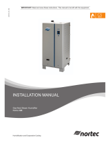
information for your MHTC / MHB
Adiabatic Air Humidifier
MH
Important: Read and save these instructions. This guide to be left with equipment.
Series

Thank you for choosing Nortec.
Proprietary Notice
This document and the information disclosed herein are proprietary data of WALTER MEIER LTD. Neither this
document nor the information contained herein shall be reproduced used, or disclosed to others without the
written authorization of WALTER MEIER LTD., except to the extent required for installation or maintenance of
recipient’s equipment. All references to the NORTEC name should be taken as referring to WALTER MEIER LTD.
Liability Notice
NORTEC does not accept any liability for installations of humidity equipment installed by unqualified personnel
or the use of parts/components/equipment that are not authorized or approved by NORTEC.
Copyright Notice
Copyright 2008, WALTER MEIER LTD. All rights reserved.
INSTALLATION DATE (MM/DD/YYYY)
MODEL #
MODEL #
MODEL #

Contents
1 Introduction
1 Limitation
1 Safekeeping
2 Safety
5 Product Overview
5 Model Overview
5 Product Designation
7 MH Flow & Reflow – Construction Model & System Overview
15 Standard Delivery, Storing, Transport, Packaging
16 Mounting and Installation
16 Unit Mounting
18 Mounting Process
31 Plumbing
31 Plumbing Overview
32 Water Supply
32 Water Quality
33 Water Drain
33 Electrical
34 Mounting the MH Control Unit
35 MH Series – Flow Wiring Diagram
36 MH Series – ReFlow Wiring Diagram
37 Operation
37 Putting into Operation
38 Adjusting the Volume Controlling Valves

39 Taking Out of Operation
39 Maintenance
40 Maintenance Intervals
41 Maintenance List
42 Dismantling and Installation Works
42 Dismantle and Install the Mist Eliminator and Humidification Boxes
43 Dismantle and Install the UV Lamp
43 Resetting the Maintenance Indication
44 Spare Parts
42 Troubleshooting
48 Taking Out of Service
49 Product Specifications
51 Unit Dimensions

MH Series | 1
Introduction
Thank you for purchasing the NORTEC MH Series adiabatic air humidifier.
The NORTEC MH adiabatic air humidifier incorporates the latest technical advances and is
designed to meet all recognized safety standards. Improper use of the humidifier may result in
danger to the user or third parties and/or damage of material assets.
To ensure safe, proper, and economical operation of the NORTEC MH Series adiabatic air
humidifier, please observe and comply with all information and safety information contained in
this manual as well as in any separate documentation related to the components installed in
the humidification system.
If you have questions, which are not answered in this documentation, please contact your
NORTEC representative, they will be glad to assist you.
Limitation
The product covered in this manual is solely the NORTEC MH Series adiabatic air humidifier.
The various accessories associated with the humidifier are only described in such detail that is
necessary for proper operation of the humidifier. Further information on accessories can be
obtained in their respective manuals.
These instructions are restricted to the installation, commissioning, operation, servicing, and
troubleshooting of the NORTEC MH Series adiabatic air humidifier and are meant for qualified
personnel. The installation and operating instructions are supplemented by various separate
items of documentation (manuals for accessories, etc.). Appropriate cross-references are
made to these publications in the installation and operating instructions.
Safekeeping
Please keep with manual in a safe place, where it can be immediately accessed. If the
equipment changes hands, the documentation must be passed on to the new operator.
If the documentation gets misplaced, please visit humidity.com or contact your NORTEC
representative.
Safety
General
Every person working with the NORTEC MH Series must read and understood the installation
and operating instructions before carrying out any work. Knowing and understanding the
contents of the installation and operating instructions is a basic requirement for protecting all
personnel against any kind of danger, to prevent faulty operation, and to operate the unit
safely and correctly.

2 | MH Series
All signs and markings applied to the unit must be observed and kept in a readable state.
Qualification of Personnel
All work (installing, operating, servicing, etc.) described in this manual may only be carried out
by a specialist who is well trained and adequately qualified and is authorized by the customer.
For safety and warranty reasons, any action beyond the scope of this manual, must be carried
out only by qualified personnel authorized by the manufacturer.
It is assumed that all persons working with the NORTEC MH Series are familiar and comply
with the appropriate regulations on work safety and the prevention of accidents.
Intended Use
The NORTEC MH Series adiabatic air humidifier/cooler is intended exclusively for air
humidification/air cooling in air ducts or air handlers within the specified operating conditions.
Any other type of application, without the written consent of the manufacturer is considered as
not conforming with the intended purpose and may lead to dangerous operation of the
NORTEC MH Series.
Operation of the equipment in the intended manner requires that all the information in these
instructions are observed (in particular the safety instructions).

MH Series | 3
Danger that May Arise From the Unit
Warning: Some components of the NORTEC MH Series are mains powered.
If the control unit or distribution boxes are open, live parts may be present. Touching live
parts may cause severe injury or danger to life.
Prevention: Before starting any work, set the NORTEC MH Series out of operation, by
switching off the unit, disconnecting it from the mains, and stop the water supply. Secure the
unit against inadvertent power-up.
Warning: The UV lamp used in the water treatment unit (option) emits harmful UV-C rays.
If the UV lamp is operated outside the housing, the emitted UV-C rays may damage the
eyes.
Prevention: Never operate the UV lamp outside the housing.
Warning: Badly maintained humidifiers can endanger health of building occupants.
If the unit is not properly maintained germs may grow in the humidifier and its
components which can cause illness and may affect the air passing through the
humidifier.
Prevention: The NORTEC MH Series must be cleaned in the intervals described in the
maintenance section of this manual. Maintenance must be carried out correctly and the
humidification boxes and the mist eliminator boxes must be replaced after their lifetime has
elapsed.

4 | MH Series
In Case of Danger
If safe operation is no longer possible, then the NORTEC MH Series should immediately be
shut down and secured against accidental power-up.
This can be the case under the following circumstances:
• If the NORTEC MH Series is damaged.
• If the NORTEC MH Series is no longer operating correctly.
• If connections and/or piping are not sealed.
• If electrical cables are defective.
Any alterations made to the NORTEC MH Series, that could affect safety, must be reported the
owner without delay.
Prohibited Modifications to the Unit
No modifications should be made to the NORTEC MH Series without the express written
consent of the manufacturer.
For the replacement of defective components only use accessories and spare parts available
from your NORTEC supplier.

MH Series | 5
Product Overview
Model Overview
The NORTEC MH is available in the two base versions “Flow” with direct water system and
“Reflow” with circulating water system. The following models are available:
• NORTEC MHB Flow (on/off control).
• NORTEC MHTC Flow (total control staging).
• NORTEC MHB Reflow (on/off control).
• NORTEC MHTC Reflow (total control staging).
All base models can be extended in their functions by different options. In addition there are
different accessories available for all models.
Product Designation
The product designation and power requirements are found on the rating plate.

6 | MH Series
Figure 1: Type Key

MH Series | 7
MHB Flow - Construction Model
# Description
1 Water connection on unit r 3/4 " (outside thread)
2 Volume controlling valves (adjustable manually)
3 Water tub
4 Open drain 1.5” pvc (1.66” (42 mm) od)
5 Water hoses
6 Spray bar cap with distribution pipes
7 Humidification boxes
8 Mist eliminator (for air speed above humidification boxes >3.8 m/s) (750 fpm)
9 Control unit on/off
Figure 2: Construction Model – MHB Flow

8 | MH Series
MHB Flow - System Overview
Figure 3: System Overview – MHB Flow
Functional Description
The MHB Flow model provides on/off control by means of the MHB control unit and an
external on/off humidistat. In case of a humidification/cooling request the supply valve opens
and the water flows via the pressure reducing valve (accessory), the water filter (accessory)
and the manually adjustable volume controlling valves to the distribution pipes above the
humidification boxes.
The distribution pipes evenly supply the water to the entire surface of the humidification boxes
where it flows down and humidifies the air flowing through the humidification boxes. The
excess water not used for humidification flows to the water tub and then directly to the drain.

MH Series | 9
MHTC Flow - Construction Model
# Description
1 Water connection on unit r 3/4 " (outside thread)
2 Volume controlling valves (adjustable manually)
3 Step valves (1 to 3)
4 Water tub
5 Open drain (outside diameter 1.5" pvc (1.66" (42 mm) od)
6 Water hoses
7 Spray bar cap with distribution pipes
8 Humidification boxes
9 Mist eliminator (for air speed above humidification boxes >750 fpm) (3.8 m/s)
10 UV water treatment (option)
11 MHTC Total Control Unit
Figure 4: Construction Model – MHTC Flow

10 | MH Series
MHTC Flow - System Overview
Figure 5: System Overview – MHTC Flow
Functional Description
The MHTC flow model provides multistep control by means of the MHTC total control unit and
the step valves (1, 2 or 3 step valves depending on the humidifier capacity). The MHTC total
control unit (for wall mounting) processes analog sensor/control signals and uses them to
control the step valves. This allows multistep control (1 to 3 steps depending on the humidifier
capacity) which improves control accuracy compared to the MHB Flow model.
In case of a humidification/cooling request one, two or all three step valves open (depending
on the request). The water flows via the manually adjustable volume controlling valves to the
distribution pipes above the humidification boxes.
The distribution pipes evenly supply the water to the entire surface of the humidification boxes
where it flows down and humidifies the air flowing through the humidification boxes. The
excess water not used for humidification flows to the water tub and then directly to the drain.
If the MHTC Reflow model is equipped with the optional uv water treatment, all the water is led
through the uv water treatment unit where it is sterilized before it is introduced to the
humidifier boxes.

MH Series | 11
MHB Reflow - Construction Model
# Description
1 Water connection on unit r 3/4 " (outside thread)
2 Level-controlled supply valve
3 Circulation pump
4 Overflow
5 Drain
6 Drain valve
7 Volume controlling valves (adjustable manually)
8 Water tub
9 Water hoses
10 Spray bar caps with distribution pipes
11 Humidification boxes
12 Mist eliminator (for air speed above humidification boxes >750 fpm) (3.8 m/s)
13 MHB control unit
Figure 6: Construction Model – MHTC Flow

12 | MH Series
MHB Reflow - System Overview
Figure 7: System Overview – MHB Reflow
Functional Description
The water tub is filled up to a preset upper level via the level-controlled supply valve. When the
water level in the tub drops below a certain limit, the level-controlled supply valve opens until
the upper limit is reached again. The pump is activated whenever the float is high and
continues to operate for a preset time after the float level drops.
The MHB Reflow model provides on/off control by means of the MHB control unit and an
external on/off humidistat. In case of a humidification/cooling request the pump is activated.
The water flows via the manually adjustable volume controlling valves to the distribution pipes
above the humidification boxes.
The distribution pipes evenly supply the water to the entire surface of the humidification boxes
where it flows down and humidifies the air flowing through the humidification boxes. The
excess water not used for humidification flows to the water tub. To prevent accumulation of
mineral residues and the formation of germs in the water tub, the tub is completely drained
periodically (interval or time controlled).

MH Series | 13
MHTC Reflow - Construction Model
# Description
1 Water connection on unit r 3/4 " (outside thread)
2 Level-controlled supply valve
3 Circulation pump
4 Overflow
5 Drain
6 Drain valve
7 Step valves (1 to 3)
8 Volume controlling valves (adjustable manually)
9 Water tub
10 Water hoses
11 Spray bar cap with distribution pipes
12 Humidification boxes
13 Mist eliminator (for air speed above humidification boxes >750 fpm) (3.8 m/s)
14 UV water treatment (option)
15 MHTC total control unit
Figure 8: Construction Model – MHTC Flow

14 | MH Series
MHTC Reflow System Overview
Figure 9: System Overview – MHTC Reflow
Functional Description
The water tub is filled up to a preset upper level via the level-controlled supply valve. When the
water level in the tub drops below a certain limit, the level-controlled supply valve opens until
the upper limit is reached again.
The MHTC Reflow model provides multistep control by means of the MHTC total control unit
and the step valves (1, 2 or 3 step valves depending on the humidifier capacity). The MHTC
total control unit (for wall mounting) processes analog sensor/control signals and uses them
to control the step valves. This allows multistep control (1 to 3 steps depending on the
humidifier capacity) which improves control accuracy compared to the MHB Reflow model.
In case of a humidification/cooling request, the circulation pump starts and one, two, or all
three step valves open (depending on the request). The water flows via the manually
adjustable volume controlling valves to the distribution pipes above the humidification boxes.
The distribution pipes evenly supply the water to the entire surface of the humidification boxes
where it flows down and humidifies the air flowing through the humidification boxes. The
excess water not used for humidification flows to the water tub.

MH Series | 15
To prevent accumulation of mineral residues and the formation of germs in the water tub, the
tub is completely drained periodically (interval or time controlled). Additionally further hygiene
functions can be activated: operation-dependent draining of the water tub (conductivity or fill
cycle controlled) as well as cleaning and drying of the humidification boxes.
If the MHTC Reflow model is equipped with the optional UV water treatment, all the water is
led through the uv water treatment unit where it is sterilized before it is introduced to the
humidifier boxes.
Standard Delivery
Standard delivery includes:
• NORTEC MH Series humidifier according to type designation (disassembled) equipped with
options according to packing list.
• Ordered accessories with operating instructions, packed separately.
• Installation and operating instructions (this document).
• Operating instructions control unit MHTC (models with control unit MHTC only).
• Spare parts list.
Storing
Store the unit and unit components in a protected area meeting the following requirements:
Room temperature: 34-104ºF (1 ... 40°C)
Room humidity: 10 ... 75 %rh
Transport
For optimum protection always transport the unit and the unit components in the original
packaging.
The weight of the unit components depends on the unit model. To move larger unit
components always ask a second person for assistance.
Packaging
Keep the original packaging of the NORTEC MH Series for later use. In case you wish to
dispose of the packaging, observe the local regulations on recycling and waste disposal. Never
dispose of the packaging to the environment.

16 | MH Series
Mounting and Installation
Qualification of personnel
All mounting and installation work must be carried out only by well qualified personnel
authorized by the owner. It is the owner’s responsibility to verify proper qualification of the
personnel.
Safety
The electrical installation requires the removal of the control unit cover. Please note the
following:
Danger of electrical shock! You may get in touch with live parts when the control unit is open. The control
unit must be connected to the mains only after all mounting and installation work has been completed and
the control unit cover has been properly secured.
The electronic components inside the control unit are very sensitive to electrostatic discharge. When the unit is
open for installation work, appropriate measures must be taken to protect these components against damage
caused by electrostatic discharge (ESD protection).
Unit Mounting
Usually, the design and dimensioning of the ventilation duct/air handler as well as the location
of the Nortec MH inside the duct are determined, recorded and specified when planning the
entire system. Prior to installation, however, make sure the following criteria have been taken
into consideration:
For operation with fully demineralised water: Fully demineralised water is aggressive! For this
reason, all components located close to the humidification unit (duct/ air handler, fastening
material, drain pipe, etc.) must be made of corrosion-proof steel or plastic.
For installation and maintenance of the humidification unit a viewing window and a sufficiently
large maintenance door must be available in the duct/ air handler.
In the area of the humidification unit the ventilation duct/ air handler must be waterproof.
Important! An air filter must be installed at the air inlet of the humidification unit. The filter
must meet the quality standards (MERV 11 (Note WMCI specifies EU7 (f7) which is equivalent
to MERV 11) ASHRAE 52.2 or better.
In case of low ambient temperature, the duct must be externally insulated to prevent the moist
air from condensing inside the duct.
Page is loading ...
Page is loading ...
Page is loading ...
Page is loading ...
Page is loading ...
Page is loading ...
Page is loading ...
Page is loading ...
Page is loading ...
Page is loading ...
Page is loading ...
Page is loading ...
Page is loading ...
Page is loading ...
Page is loading ...
Page is loading ...
Page is loading ...
Page is loading ...
Page is loading ...
Page is loading ...
Page is loading ...
Page is loading ...
Page is loading ...
Page is loading ...
Page is loading ...
Page is loading ...
Page is loading ...
Page is loading ...
Page is loading ...
Page is loading ...
Page is loading ...
Page is loading ...
Page is loading ...
Page is loading ...
Page is loading ...
Page is loading ...
Page is loading ...
Page is loading ...
/