Page is loading ...

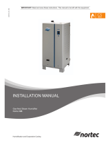
MH
Series
Installation and
Operation Manual
Includes installation, operation,
maintenance, and troubleshooting
information for your MHTC / MHB
evaporative humidifier / cooler.
2558966-E | 27 NOV 2013
Important:
Read and save these instructions. This guide to be left with equipment.

Thank you for choosing Nortec.
Proprietary Notice
This document and the information disclosed herein are proprietary data of Nortec Humidity Ltd. Neither this
document nor the information contained herein shall be reproduced used, or disclosed to others without the
written authorization of Nortec Humidity Ltd., except to the extent required for installation or maintenance of
recipient’s equipment. All references to the Nortec name should be taken as referring to Nortec Humidity Ltd.
Liability Notice
Nortec does not accept any liability for installations of humidity equipment installed by unqualified personnel or
the use of parts/components/equipment that are not authorized or approved by Nortec.
Copyright Notice
Copyright 2013, Nortec Humidity Ltd. All rights reserved.
INSTALLATION DATE (MM/DD/YYYY)
MODEL #
SERIAL #

Contents
1 Introduction
2 Receiving and Unpacking
3 MH Components
5 MH Models
6 Options and Accessories
11 Installation
12 Typical MH Installation
13 Location – Duct Module
14 Location – MHTC Reflow Hydraulic
Unit
15 Duct Module Assembly and
Installation
22 Plumbing
25 Electrical
27 External Controls
34 Options and Accessories
35 Start Up
36 Installation Check
37 MHTC User Interface
38 Start Up Procedure
39 MHTC Status Screens
41 Nortec Digital Controls
43 Start Up Checklists
45 Operation
46 MHTC LED Status Lights
46 MHB Status Lights
47 MH Schematic
47 How the MH Works
50 MHTC Humidifier Configuration
57 MHB Configuration
59 Maintenance and
Servicing
60 Required Maintenance
62 Maintenance Schedule
68 Maintenance Shutdown and
Extended Shutdown
69 Maintenance Checklist
70 Troubleshooting
72 General Troubleshooting
74 MHTC Warnings and Faults
78 Wiring Diagrams
83 Spare Parts
90 Warranty

1 | Introduction
Introduction
CAUTION: Servicing
Every person working with the NORTEC MH Series must read and understand the
installation and operating instructions before carrying out any work.
Disconnect main power before any servicing.
The control box and hydraulic unit contain high voltage components and wiring.
Access should be limited to authorized personnel only.
Poorly maintained humidifiers / coolers can endanger health of building
occupants. If the MH is not properly maintained microbials may grow in it. If
carried by air passing through the humidifier the germs can cause illness.
The MH must be serviced in the intervals described in the maintenance section of
this manual. Humidification boxes and mist eliminator media must be replaced
after their service life has elapsed.
CAUTION: Electrical
All electrical work should be done according to local electrical code.
Electrical connection to be performed by a licensed electrician.
CAUTION: Plumbing
Plumbing to be performed by a licensed plumber.
All plumbing work should be done according to local plumbing code.
Unit damage caused by water quality outside of the specified ranges is not
covered under warranty.
CAUTION: Installation
Do not mount control box or hydraulic unit on hot surfaces
Do not mount hydraulic unit in area where freezing can occur
Do not mount control box or hydraulic unit on vibrating surface
Regardless of selecting On/Off or modulating control method, Nortec humidifiers
must have a closed circuit across its On/Off security loop control terminal to
operate. Nortec highly recommends the use of a high limit humidistat and an air
proving switch in series for this function.
Nortec Humidity Ltd. does not accept any liability for installations of humidity
equipment installed by unqualified personnel or the use of
parts/components/equipment that are not authorized or approved by Nortec
Humidity Ltd.

Introduction | 2
Receiving and Unpacking
1 Check packing slip to ensure ALL material has been delivered.
2 All material shortages are to be reported to Nortec within 48 hours from receipt of goods.
Nortec assumes no responsibility for any material shortages beyond this period.
3 Inspect shipment for damage and note damages on shipping waybill accordingly.
4 After unpacking, inspect equipment for damage and if damage is found, notify the shipper
promptly.
5 All Nortec products are shipped on an FOB factory basis. Any and all damage, breakage or
loss claims are to be made directly to the shipping company.
Before Installation
1 Ensure that available voltage and phase corresponds with humidifier voltage and phase as
indicated on humidifier’s specification label.
2 Ensure sufficient clearances will be available for P-Trap on drain pan overflow and for proper
slope of drain line from hydraulic unit.
3 Ensure sufficient clearances will be available as described in Location on page 13.
4 Ensure duct access will be available from downstream of duct manifold to install, maintain,
and replace media boxes.
5 Report any discrepancy immediately to the site engineer.
Figure 1: Specification Label Location
Note:
Each MH is shipped in multiple packages containing; 1) Control Box, 2) Hydraulic Unit,
3) Drain pan and duct manifold sheet metal, 4) Media Boxes, 5) Mist Eliminator
(if ordered).

3 | Introduction
MH Components
Figure 2: MH Humidifier Components
High Voltage
Terminal Block
On/Off Switch
Display and Keypad
Drain Outlet
Media Boxes
Spray Bar
Cap
Spray
Bars
Right
Side Panel
Duct Seal
Mist
Eliminator
Intermediate
Member
Drain
Pan
Water Lines
Pressure
Equalization
Line
Drain Pan
Drain
Hydraulic
Unit
Drain Overflow
Control
Box
Conductivity
Sensor
Float
Check
Va lve
Fill
Valve
Staging
Manifold
Staging
Valve
Pressure
Equalization
Line
Pump
UV Light
Reservoir
Drain Valve
Fuse Block
Pump and U
V
Light Relay
Transformer
Conductivity
Transmitter
Low Voltage
Terminal
Block
(Hydraulic
Unit )

Introduction | 4
Description of Components
Table 1: Humidifier Components
Component Function of Component
Check Valve Provides back flow protection for supply water line.
Conductivity Sensor
/Transmitter
Sensor measures conductivity of water in the reservoir. Transmitter
sends measured value to control box for use in water quality control.
Control Box /
Display and Keypad
Controls all functions of the humidifier’s operation and provides user
interface for configuration of the humidifier.
Drain Pan Collects unevaporated water from media for recirculation or draining.
Drain Pan Drain Drain pan connection to hydraulic unit reservoir.
Drain Outlet Drain connection from the hydraulic unit.
Drain Overflow Provides protection from overfilling the drain pan.
Drain Valve Drains water from the reservoir.
Duct Seal Prevents duct air flow from bypassing the humidifier.
Fill Valve Controls makeup water flow to humidifier based on float level.
Float Measures water level in reservoir to prevent over filling.
Fuse Block Overcurrent protection for pump and UV light.
High Voltage
Terminal Block
Primary voltage connection on hydraulic unit and in control box.
Hydraulic Unit Collects water from the
drain pan and pumps, treats with UV light, and
stages water to media. Fills and drains reservoir to control water quality.
Intermediate
Member
Structural member supports media boxes.
Low Voltage
Terminal Block
Hydraulic Unit –
connects control box inpu
t
s to the hydraulic unit.
Control Box – provides connection for control signals and safety loop.
Media Boxes Surface from which water is evaporated for humidification/cooling.
Mist Eliminator Captures any water droplets that are carried off the media boxes with air
flow in high duct speed applications.
On/Off Switch Turns power On/Off to humidifier controller. Note: Turn off humidifier
disconnect to shut off primary power to the humidifier.
Pressure
Equalization Line
Balances pressure in hydraulic unit
reservoir with pressure in duct to
ensure proper water flow to reservoir from drain pan.
Pump Pumps water from the reservoir to the media boxes.
Pump and UV Light
Relay
Turns on power to the UV light and pump based on signal from the
control box.
Reservoir Collects water from the drain pan for recirculation / draining.
Side Panel, Right Structural member supports media boxes and spray bar cap.
Spray Bar Cap/
Spray Bars
Distributes water to the media boxes and prevents water from spraying
anywhere else.
Staging Manifold /
Valve(s)
Controls flow of water to media boxes based on demand.
Transformer Steps primary voltage down to 24 VAC for the controller and internal
components such as the fill valve and drain valve.
UV Light Eliminates any bacteria in
t
he water being pumped to the media boxes.
Water Lines Supply water lines from hydraulic unit to spray bars.

5 | Introduction
MH Models
The MH2 is available in three models
(See Figure 3: MH Models and Table : MH Specifications.)
MHTC Reflow - provides state of the art control technology with staged output to match
demand. The Reflow model also includes a hydraulic unit that provides maximum water
conservation by recirculating unevaporated water.
MHTC Flow - provides the same state of the art control technology but without the hydraulic
unit for recirculating water. The MHTC Flow can be multi stage for matching output to
demand or single stage. Due to the aggressiveness of ultrapure DI water, potable or RO
water is recommended for Flow systems.
MHB - provides basic operation without user configurable settings. The MHB can be multi
stage for matching output to demand or single stage. Due to the aggressiveness of ultrapure
DI water, potable or RO water is recommended for MHB systems.
Figure 3: MH Models
Each MH model is coupled with a duct module that contains the evaporative media used for
humidifying / cooling the duct air. The duct module is basically the same for each model with
the exception of the number of spray bars which are used for staging output.
MHTC Reflow MHTC Flow MHB
Single StageMulti Stage
OR

Introduction | 6
Options and Accessories
Nortec provides a complete line of options and accessories for every humidification application.
The following options and accessories are available and may have been delivered with your
MHTC humidifier/cooler. Refer to the installation instructions that came with the accessories
for their proper installation and operation.
Table 2: Options and Accessories
Option / Accessory Used For
Mist Eliminator Removing water droplets that have been picked up by the air
stream as it flows through the evaporative media.
Conductivity Sensor Measuring water conductivity in the MHTC Reflow reservoir for
improved water management.
Water Filters Removing foreign particles from water supplied to the MH.
Water Pressure Regulators Reducing supply line water pressure supplied to the MHTC Flow
and MHB.
Digital or Analog Control Humidistats Controlling the output of the humidifier based on sensed RH (can
be mounted in the space being humidified or in the duct).
Digital RH Transducers Communicating RH in a space or duct to the humidifier
Digital or Analog High Limit Humidistats Preventing over humidification in a duct by shutting down or
throttling down the humidifier when duct RH gets high.
Air Proving Switches Insuring humidification only occurs when air is moving in a duct.
Nortec LINKS XPS (MHTC Only) Connecting the humidifier to a building management interface.
hardware allows control of the humidifier via BACnet, Lonworks,
Johnson N2, or Modbus.
MH Specifications
Table 3: MH Specifications
MHB Flow MHTC Flow MHTC Reflow
Voltage
120 vac / 60 hz 120 vac / 60 hz 120 vac / 60 hz
Control signals
VDC 0-10 VDC 0-5, 1-5, 0-10,
2-10, 0-16, 3.2-16
mA 0-20, 4-20
VDC 0-5, 1-5, 0-10,
2-10, 0-16, 3.2-16
mA 0-20, 4-20
Max No. of Stages
3 3 3
Water supply
3/4 in. BPP, 1/2 in.
NPT adapter provided
1/2 in/ FPT 3/4 in. BPP, 1/2 in.
NPT adapter provided
Water drain
2 in. (50.8 mm) OD
t
ube
2 in. (50.8 mm) OD
t
ube
2 in (50.8 mm) ID
hose
Control accuracy
Depends on air conditions, number of stages, and control setup
Allowable water supply pressure
30-80 psi (2-5.5 Bar)
Allowable water temperature
41-104ºf (5-40ºc)
Water quality
Tap water, reverse osmosis, softened or fully demineralized water.
Note: Ultrapure DI water not recommended on MHB or Flow Systems.
Max. allowable velocity through media
1100 fpm (5.5 m/s) with mist eliminator.
Pressure drop
Typically 0.44 IWC (250 Pa) @ 500 fpm (2.5 m/s) and 90% RH
Ambient conditions (control unit)
34 -104ºF (1- 40ºC) Max 75% RH
Max. allowable air temp. through media
120 ºF (48 ºC)
Fire classification of evaporative media
UL 900 Class 1 USA, ULC-S111-07 Class 2 Canada

7 | Introduction
MH Dimensions
Figure 4: MHTC Reflow/Flow Control Box Dimensions
Figure 5: MHB Control Box Dimensions
12.0 in.
30.5 cm
16.7 in.
42.5 cm
14.3 in.
36.3 cm
4 x 5/16 in
O
(8 mm)
6.2 in.
15.6 cm
17.5 in.
44.4 cm
9.3 in.
23.6 cm
6.0 in.
15.2 cm
10.75 in.
27.3 cm
11.5 in.
29.2 cm
5.4 in.
13.6 cm
4 x 0.31 in. O
(8 mm)

Introduction | 8
Figure 6: MH Duct Module Dimensions
4.2 in.
10.7 cm
1.0 in.
2.7 cm
TYP
74.6 in.
189.6 cm
8.4 in.
21.5 cm
4.9 in.
12.5 cm
2.8 in.
7 cm
4.1 in.
10.3 cm
H=24 - 144 in.
(0.6 - 3.7 m)
12 in. (30 cm) Supplied
Cut to Desired Length
16.6 in.
42.3 cm
0.6 in.
1.6 cm
W - 1.2 in (W - 3.2 cm)
W/2 - 0.6 in.
(W/2 - 1.6 cm)
15.8 in.
40.2 cm
W = 24 - 144 in.
(0.6 - 3.6 m)
O
0.2 in.
0.6 cm
6 X
Overflow
2 in. (50.8 mm)
Tube
Drain
2.0 in (50.8 mm)
Tube
1-3 x Spray Bar
1/2 in. (12.7 mm)
Tube

9 | Introduction
Figure 7: MHTC Reflow Hydraulic Unit Dimensions
Figure 8: MHTC Flow/MHB Multi Stage Hydraulic Unit Dimensions
11.8 in.
29.9 cm
2.4 in.
6.1 cm
2.0 in.
5.2 cm
12.1 in.
30.7 cm
2.1 in.
5.3 cm
6.4 in.
16.4 cm
2.6 in.
6.7 cm
2.6 in.
6.7 cm
8.2 in.
20.8 cm
2.4 in.
6 cm
17.6 in.
44.6 cm
15.6 in.
39.5 cm
11.5 in.
29.2 cm
2.0 in.
5.1 cm
2.0 in.
5.2 cm
10.0 in.
25.5 cm
2.5 in.
6.4 cm
Water Inlet
3/4 in BSP
(1/2 in. NPT
Adapter
provided)
Drain Pan
Connection
2 in. Tube
Drain
2 in. ID Hose
Spray Bar
Connections
1-3 x 1/2 in.
(13 mm) Hose Barb
Press. Equal.
1/2 in. (13 mm)
Hose Barb
Electrical
3 x 7/8 in.
(22 mm)
24.1 in.
61.3 cm
11.87
30.15
8.05
20.45
9.87
25.07
1.00
2.55
11.88
30.16
1.32
3.36
1.31
3.33
1 - 3 x 1/2 in. OD
Barbed Hose
2 x 1/4 in. O
(6.4 mm)
2 x Water Tight
Strain Relief
Electrical Connection
Water Inlet
1/2 in. NPT
Drain
1/2 in. NPT

Introduction | 10
Figure 9: MHB Single Stage Hydraulic Unit Dimensions
1.8 in.
4.4 cm
2.7 in.
6.8 cm
4.3 in.
10.9 cm
Water Inlet
3/4 in GHT
Spray Bar
Connection
1/2 in (13 mm)
Hose Barb
2 x 0.3 in. O
(7.6 mm)

11 | Introduction
Installation

Installation | 12
Typical MH Installation
Figure 10: Typical MH Installation
L1
N
Ground
Dedicated
Circuit Breaker
or Disconnect
MH
EXT
Connect spray bar lines
to spray bar.
Spray Bar Lines
Water Supply
30-80 psig
Drain and
overflow lines
Pressure
Equalization
Line
Drain pan
to hydraulic
unit
Spray Bar Lines
Pressure
Equalization Line*
Drain Pan to
Hydraulic Unit*
P-Trap
Spray Bar Lines
Connect to drain pan
overflow on Reflow or
to drain on Flow.
Control box to
hydraulic unit
wiring
(13-17 wires)
Reflow and Flow only
Control Box
Duct Module
Hydraulic Unit
Hydraulic
unit drain*
Note: MHTC Reflow show.
* = only required on
Reflow model.
E
X
T
M
H
1- 24 VAC
2 - On/Off Loop
3 - Ground
4 - Control Signal
5 - N/A
6 - +5 VDC
7 - Ground
On/Off
Controls
Modulation
Control
c
l
y
Plumbing
Pg 22
Duct Module
Assembly
Pg 15
Hydraulic
Unit
Location
Pg 14
Controls
Pg 27
Electrical
Pg 25

13 | Installation
Location – Duct Module
The MH Duct module is designed to be installed on the floor of a duct or air handler. Position
the drain pan so that there is an equal gap between the pan and both side walls. The drain pan
should be oriented so that the media boxes and overflow will be upstream of the drain pan
outlet.
Ensure mounting surface is strong enough to support the full weight of the duct module,
mist eliminator and water in the evaporative media and drain pan (see MH Specifications
Table 3: MH Specifications for approximate weights).
Provide a watertight section in the area of the duct unit that extends a min. of 36 in (92cm)
from the end of the duct module. If demineralised water is used use corrosion resistant
materials.
A mist eliminator is not required for media face velocities below 750 fpm; however as the
media reaches its end of life, there is a risk of droplet carry over. A drain is required in the
watertight section downstream from the duct module.
Air filters meeting ASHRAE 52.2 MERV 8 or MERV 11 must be installed upstream of the MH
duct module.
Ensure an access door and sufficient space for replacing media boxes is provided
downstream of the MH duct module. Provide extra space for opening /removing mist
eliminator to access media boxes if mist eliminator is installed.
In case the outside of the duct or air handler walls are in contact with low ambient
temperature insulate the outside of the duct to prevent condensation inside the duct.
Clearance dimensions shown are for reference only and are the minimum required for
maintenance of the humidifier. Consult local and national codes before final location and
installation. Nortec does not accept responsibility for installation code violations.
Figure 11: MH Duct Module Location

Installation | 14
Location – MHTC Reflow Hydraulic Unit
The MHTC Reflow Hydraulic Unit should be located adjacent to the duct or air handler
containing the MH Duct Module. The Hydraulic Unit is designed to be floor mounted but can be
installed on a stand or raised surface.
Install the hydraulic unit as close as possible to the MH Duct Unit to minimize length of drain
and spray bar lines.
Ensure spray bar lines are no longer than 15 ft. vertically (equivalent length per spray bar).
below the top of the duct module.
Ensure the Hydraulic Unit is installed on a level surface.
Install providing access for removal of cover and servicing of unit.
Figure 12: Installation Location / Clearance
Note:.
A P-Trap equal to duct static pressure plus 2 inches must be installed on the drain pan
overflow. Ensure sufficient space is available. Use a stand to raise the drain pan in the
duct if necessary.
Note:
The Duct Unit requires regular maintenance including replacement of media boxes. Ensure
access and sufficient space is provided downstream of the unit to remove and install new
media boxes.
2 in.
(5 cm)
10 in.
(25 cm)
As close as
possible to
spray bars.
5-95%
24 in. (60 cm) Min.
top clearance
Can be placed
as close to duct
as possible
leaving room for
inlet water, drain
and spray bar
connections.
Floor mount to ensure duct module drain pan to hydraulic
unit connection and the drain line can be adequately sloped.
Min. front
clearance
Min. side
clearance
2 in.
(5 cm)
Min. side
clearance
Mount
Hydraulic Unit Level
Drain below drain pan outlet.

15 | Installation
Duct Module Assembly and Installation
Usually, the design and dimensioning of the ventilation duct/air handler as well as the location
of the Nortec MH inside the duct are determined, recorded and specified when planning the
entire system. The following 8 steps provide a guide for assembling the duct unit. Assembly
should only be carried out by qualified personnel familiar with duct and air handler construction.
The assembly shown shows the drain pan being mounted and fastened to the base of the duct.
It may be necessary to raise the drain pan in the duct to achieve proper P-Trap height on the
drain or overflow. Ensure proper height is available for a P-Trap equal to 6 in (15 cm) or duct
static pressure + 2 in whichever is greater.
Step 1 - Drain Pan
Figure 13: Drain Pan Installation
Air
Flow
Cutout
Duct
Install hose
cuffs on both
tank drain
connections.
1/4 x 3/4 Self
tapping screws (6x)
Drain Pan
Equal gaps
Overflow Outlet
Drain Pan Drain
Outlet
Duct or air handler
plenum
Install drain pan
ensuring it is level.
Orient the drain pan
with respect to air flow
so that the overflow
outlet (higher) is
upstream of the drain
pan drain outlet.
Leave an equal gap on
both sides of the drain
pan.
Caulk around screws
and any other openings
used to fasten the
drain pan to the base
of the duct.
Make a cutout in the
side of the duct for
drain connections and
install hose cuffs of
sufficient length to
connect to hydraulic
unit or drains.
Seal duct wall around
hose cuffs with cover
plate (by others).

Installation | 16
Step 2 – Side Panels
Step 3 – Top Bracket and
Intermediate Members
Air
Flow
Side panels
Air
Flow
Intermediate
members
Top Bracket
Install side panels onto
the drain pan using 1/4
UNC x 3/4 in. screws,
washers, and ¼” UNC
locknuts.
Ensure flanges for
mounting media boxes
are upstream with
respect to airflow.
Figure 14: Side Panel Assembly
Install top bracket and
intermediate members
to side panels and
drain pan using 1/4
UNC x 3/4 in. screws,
washers, and ¼” UNC
locknuts.
Tighten screws finger
tight for ease of
assembly, tighten
completely in step4.
Figure 15: Top Bracket /and
Intermediate Member assembly

17 | Installation
Step 4 – Block Side Panels
Step 5 - Seal Around Duct
Air
Flow
Air
Flow
Side seal
Clamping
bars
Top S eal
Ensure both side panels
are square to drain pan
edge.
Insert blocks (by others)
between side panel and
duct wall to keep them
in place. Shim as
required.
Secure blocking material
to side panels with
screws (by others) using
holes provided in side
panels.
Tighten all previously
installed screws.
Figure 16: Square and Block Side
Panels.
Seal air gap between
side panels and duct
walls as well as between
top bracket and duct
ceiling with either EPDM
sealing profile (optional)
or sheet metal angles
(by others).
To install sealing profiles
cut to duct height and
duct width plus
allowance.
Attach profiles to side
panels and top bracket
with clamping brackets
and self-tapping screws
#10 x 3/4" supplied.
Trim profiles to fit and
attach them to the duct
walls and ceiling using
brackets and screws
Figure 17: Seal Around Duct
/