ASCO POWER TECHNOLOGIES 7000 Series User manual
- Category
- Power supply units
- Type
- User manual
This manual is also suitable for

381333–309
50 Hanover Road, Florham Park, New Jersey 07932–1591 USA
For sales or service call 1 800 800–2726 (ASCO) www.ascopower.com
ASCO POWER TECHNOLOGIES CANADA PO Box 1238, 17 Airport Road, Brantford, Ontario, Canada N3T 5T3
telephone 519 758–8450, fax 519 758–0876, for service call 1 888 234–2726 (ASCO) www.asco.ca
Operator’s
Manual
7000 Seri es 7ADTB
Automatic Delayed–Transition Transfer
& Bypass–Isolation Switches
J des ig n 150 thro ug h 600 amp .
DANGER is used in this manual to warn of high
voltages capable of c ausi n g sh oc k , burn s, or death .
WARNINGisusedinthismanualtowarn
of possible personal injury.
CAUTIONisusedinthismanualtowarn
of possible equipment damage.
Refer to t he outline and wiring drawings provided
with your 7000 Series ADTB for all installation and
connection details and accessories.
Refer to Group 5 Controller U ser’s Guide 381333–126
for ATS status display messages, time delays, pickup
& dropout settings, and adjustments.
An experienced licensed electrician must install the
7ADTB.
Rating Label
Each 7000 Series 7ADTB contains a rating label to
def in e t h e lo ad and fau lt circ u it withst an d /c lo sin g
ratings. Refer to the label on the Transfer Switch for
spec ific values.
Do not exceed the values on the rating label.
Exceeding the rating can cause personal injury
or serious equipment damage.
TABLE OF CONTENTS
section-page
INSTALLATION
Mounting 1-1.............................
Power Connections 1-1....................
Engine Starting & Auxilia ry Circuits 1-2......
Functional Test 1-2, 1-3, 1-4.................
TESTING & SERVICE
Transfer Test 2-1..........................
Preventive Maintenance 2-1................
Disconnecting the Controller 2-1............
Manual Load Transfer 2-2..................
Trouble-Shooting 2-2......................
BYPASSING & ISOLATING
Bypassing the ATS 3-1, 3-2.................
Isolating the ATS 3-3, 3-4...................
Return to Service 3-5, 3-6, 3-7...............
INDEX back cover.........................

Namepl ate
The Transfer Switch nameplate includes data for each
specific 7000 Series ADTB. Use the switch only within the
limits shown on this nameplate. A typical Catalog Number
is shown below with its elements explained.
Catalog Number Identification
Typical 7000 Series ADTB catalog no. for overlapping
neutral, 3 pole, 600 amp, 480 V, ATS in Type 1 enclosure:
J7ADTB C 3 600 N 5 C
Phase Poles
Neutral
A –solid
Amperes Voltage Controller Enclosure
B –switched
5X –if
accessories
ordered
5 –standard
G –type4
C –type1
F –type3R
L –type12
3 –threeØ
2 –singleØ
D 220
C 208
E 230
K 415
M 460
J 400
L 440
N 480
G 277
F 240
H 380
Q 575
P 550
R 600
600
400
260
blank – none
blank – open type
150
A 115
B 120
Transfer
Switch
(insid e)
Bypass
Handle
Group 5
Controller
Standard
Controls
&Indicators
Isolation
Handle
Transfer/Bypass
Status Panel
optional
Accessory

SECTION 1 INSTALLATION
1 --- 1
A SCO 7000 Series A utomatic Delayed–Transition
Tra nsfer & Bypass–Isolati on Switches (7ADTBs) are
factory wired and t ested. Field installation requires
mounting and connectio n of service cables, and auxiliary
control circuits (if required).
Remove the Shipping Skid
Open the front door and remove the four lag screws (2 in
front, 2 in rear) securing enclosure to the shipping skid.
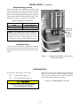
Supporting Foundation
The supporting foundation for the enclosure must be
level and straight. Refer to the applicable enclosure
outline drawing included with the switch for all mounting
details including door opening space.
If bottom cable entry is used, the foundation must be
prepared so that the conduit stubs are located correctly.
Refer to the enclosure outline drawing for specified area
and location. Provide cable bending space and clearance
to live metal parts. When a concrete floor is poured, use
interlocking conduit spacer caps or a wood or metal
template to maintain proper conduit alignment.
Mounting
Refer to the applicable enclosure outline drawing fur-
nished with this switch and mount the automatic transfer
switch according to details and instructions shown on
diagram.
Line Connections
Refer to the Wiring Diagram provided with the swit ch.
All wiring must be made i n accordance with the National
Electrical Code and local codes.
Do not remove the interphase barriers from the transfer
switch. Always protect the transfer switch, bypass switch,
and isolation contacts and mechanisms from construc-
tion grit and metal chips when cabling.
De–energize the conductors before making any
line or auxiliary circuitry connections. Be sure
that Normal and Emergency line connections
are in proper phase rotation. Place engine gen-
erator starting control in the OFF position. Make
sure engine generator is not in operation.
Te sting Power Conductors
Do not connect the power conductors to the transfer
switch until they are tested. Installing power cables in
conduit, cable troughs and ceiling-suspended hangers
often requires considerable force. The pulling of cables
can damage insulation and stretch or break the
conductor’s strands. For this reason, after the cables are
pulled into position, and before
they are connected, they
should be tested to verify that they are not defective or
have been damaged during installation.
Protect the switch from construction grit
and metal chips to prevent malfunction or
shortened life of the 7ADTB switch.
Connecting Power Conductors
After the power cables have been tested, connect them to
the appropriate terminal lugs on the bypass switch as
shown on the wiring diagram provided with the switch.
Make sure the lugs provided are suitable for use with the
cables being installed. Standard terminal lugs are solder-
lessscrewtypeandwillacceptthewiresizeslistedonthe
drawings provided with the 7ADTB. Be careful when
stripping insulation from the cables; avoid nicking or
ringing the conductor. Remove surface oxides from
cables by cleaning with a wire brush. When aluminum
cable is used, apply joint compound to conductors.
Tighten cable lugs to the torque specified on rating label.
Controller Ground
A grounding wire must be connected to the controller’s
lower left mounting stud. Because the controller is
mounted on the enclosure door, a conductive strap must
be used between the enclosure and the door. This
connection provides proper grounding which does not
rely upon the door hinges.
Harnesses
The transfer switch is connected to the left side of the
controller by a plug–in harness (two plugs).

INSTALLATION (continued)
1 --- 2
Engine Starting Contacts
All customer connections, including the engine control
contact connections, are located on terminal block TB
which is mounted on the top right side of the enclosure.
Refer to the wiring diagram provided wi th the automatic
transfer switch and connect the engine start wires to the
appropri ate terminals. See Figure 1–1 and Table A.
Table A. Engine start connections.
When normal source
fails
Te rm ina l s o n
Te rm ina l B l o c k TB
contact closes TB1 and TB2
contact opens TB1 and TB3
Note: To temporarily disable engine control from
the automatic transfer switch you can unplug J3
from the small P3 receptacle at the bottom of the
assembly. BesuretoreconnectplugJ3totheP3
receptacle for automatic transfer switch operation.
Auxiliary Circuits
Connect auxiliary circuit wires to appropriate terminals
on transfer switch terminal block TB as shown on the
wiring diagram provided with this automatic transfer
switch.
engine start
connections
on
customer
terminal
block TB
Figure 1-1. Customer terminal block on the top right
side of the enclosure.
Functional Test
The Functional Test consists of two checks:
❐ 1—VoltageChecks,page1–3
❐ 2 — Electrical Operation, page 1–4
Do these checks in the order presented
to avoid damaging the 7ADTB.
Read all instructions on t he Wiring Diagram and labels
affixed to t he automatic transfer & bypass–isolation
switch. Note the control f eatures that are provided and
review their operation before proceeding.
Continue to 1–VoltageChecks on next page.

INSTALLATION
(continued )
1 --- 3
RED
RED
GREEN
GREEN
observe
these lights
AMBER
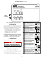
Figure 1-2. Standard controls and indicators.
Functional Test
Read all instructions on the Wiring Diagrams and labels
affixed to the 7ADTB. Note the control features that are
provided and review their operation before proceeding.
After installing the 7ADT B check the following:
– Bypass Handle should be in the NORMAL position.
– Isolation Handle should be in the CONN position.
– CN transfer switch should be C (closed)
– CE transfer switch should be O (open)
If handles are not in correct positions, follow instructions
for Bypassing and Isolating the automatic transfer switch
in Section 3. Do not force the handles. Electrical
interlocks prevent a wrong sequence of operation.
1–VoltageChecks
First check nameplate on transfer switch; rated voltage
mustbethesameasnormalandemergencylinevoltages.
Useextremecautionwhenusingameter
to measure voltages. Do not touch power
terminals; shock, burns, or death could result !
Perform steps 1–6 at the right. Observe the status lights.
See Figure 1–2.
■ Black square means light is on.
❐ White square means light is off.
* If necessary, adjust voltage regulator on generator per the
manufacturer’s recommendations. The 7ADTB will respond only
to rated voltage specified on the nameplate.
Now continue to 2 – Electrical Operation on next page.
1
Close the normal source circuit
breaker. The Transfer Switch
Connected To Normal and the
Normal Source Accepted lights
should come on.
Load
Disconnect
Active
2
Use an accurate voltmeter to
check phase to phase and
phase to neutral voltages pres-
entatthetransferswitchnormal
source terminals.
3
Close the emergency source
circuit breaker. (Start generator,
if necessary.) The Transfer
Switch Connected To Normal &
Emergency Source Accepted
lights should come on.
Load
Disconnect
Active
4
Use an accurate voltmeter to
check phase to phase and
phase to neutral voltages pres-
ent a t the transfer switch emer-
gency source terminals.*
5
Useaphaserotationmeterto
check phase rotation of emer-
gency source; it must be the
same
as the normal source.
A
B
C
6
Shut down the engine–genera-
tor, if applicable. The Emergen-
cy Source Accepted light should
go off. Then put the starting
control selector sw itch (on the
generator set) in the automatic
position. Close enclosure door.
Load
Disconnect
Active

INSTALLATION (continued)
1 --- 4
RED
RED
GREEN
GREEN
observe
these lights
AMBER
operate
this switch
Figure 1-3. Standard controls and indicators.
2 – Electrical Operation
This procedure checks electrical operation of the ADTS.
Close en c losu r e door before proc ee ding to prev e n t
personal injury in case of electrical system fault.
Transfer Test
The ATS should still be bypassed. Both normal and
emergency sources must be available and the emergency
source generator (if used) must be capable of bei n g
started; put engine starting control in automatic position.
The Transfer Swit ch Connected to Normal light and the
Normal Source Accepted light should be on.
1. Turn the Isolation Handle counterclockwise to the
TEST position.
NOTE: The engine generator may be signalled to start while
turning the Isolation Handle. If emergency source is available,
the ATS may operate to the emergency position. If it does,
operate R etransfer Delay Bypass switch.
2. Perform steps 1–5 at right. Observe the status lights.
See Figure 1–3.
■ Black square means light is on.
❐ White square means light is off.
3. Turn the Isolation Handle clockwise to the CONN
(connected) position.
4. Turn Bypass Handle clockwise to the OPEN position.
This completes the Functional Test of the 7ADTB.
1
Turn and hold Transf er Contro l
switch clockwise to Transfer
Test until the engine starts
and runs (within 15 sec.). The
Emergency Source Accepted
light should come on.
Load
Disconnect
Active
2
Transfer switch CN opens and
the Transfer Switch Connected
to Normal light should go off
and the Load Disconnect Active
light should come on. Both CN
& CE contacts are now open.
Load
Disconnect
Active
3
After the delay transition time
delay, the CE Transfer switch
will operate to the Emergency
position. The Transfer Switch
Connected To Emergency light
should come on and Load Dis-
connect Active light goes off.
Load
Disconnect
Active
4
Transfer switch will operate
back to Normal position after
Feature3Atimedelay.Forim-
mediate retransfer turn Transfer
Control counterclockwise to
Retransfer Delay Bypass.The
Transfer Switch Connected To
Normal light should come on;
Transfer Switch Connected to
Emergency light should go off.
Load
Disconnect
Active
5
The engine–generator will stop
after the Feature 2E time delay
(unloaded running engine cool-
down). The Emergency Source
Accepted light should go off.
Load
Disconnect
Active

SECTION 2 TESTING & SERVICE
2--1
TRANSFER TEST
Test the Automatic Transfer Switch portion of t he 7000
Series 7ADTB at least once a month. This procedure
checks the electrical operation of the Transfer Switch and
Controller. Put the engine–generator starting control (at
the engine–generator set) in automatic mode.
In the following test the generator will start, the load will
be transferred to the Emergency source, then back to the
Normal source. An interruption to the load will occur, un-
less the the Transfer Switch contacts are bypassed before
the test. See pages 3–1 through 3–4 for bypassing & iso-
lating instructions if no interruption of load is required.
Be sure to close the enclosure door
before proceeding to prevent personal injury
in case of electrical system fault.
Perform the five–step Electrical Operation – Transfer
Tes t procedure on page 1–4.
PREVENTIVE MAINTENANCE
Reasonable care in preventive maintenance will insure
high reliability and long life for the 7000 Series 7ADTB.
An annual preventive maint enance program is recom-
mended.
ASCO Services, Inc. (ASI) is ASCO Power
Technologies’s nati onal service organization. In the
US ASI can be contacted at 1-800-800-2726 for in-
formation on preventive maintenance agreements.
Checklist f or Yearly Inspection
Hazardous voltage capable of causing shock,
burns, or death is used in this switch.
Deenergize both Normal – Emergency power
sources before performing inspections!
❐ Clean the 7ADTB enclosure.
Brush and vacuum away any excessive dust accumu-
lation. Remove any moisture with a clean cloth.
❐ Check the transfer switch contacts.
Bypass, isolate, and withdraw the transfer switch.
Then remove the transfer switch interphase barriers
and check the condition of the contacts. Replace con-
tacts when pitted or worn excessively. Reinstall the
interphase barriers carefully. See page 3–4.
❐ Maintain transfer switch lubrication.
If switch is sub j ec ted to severe dust or abn orm al
operating conditions, renew factory lub rication on
all mov em ents and l inkages. Relubr ic ate solenoid
oper ato r if TS co il is repl ac e d . Don’t use oil; order
lubrication kit 75-100.
❐ Check all cable connections & retighten them.
REPLACEMENT PARTS
Replacement parts are available in kit form. When or-
dering parts provide the Serial No., Bill of Material No.
(BOM), and Catalog No. from the transfer switch name-
plate. Contact your local ASCO Power Technologies
Sales Office or ASI:
In the U nited States
call 1 – 800 – 800 – ASCO ( 2726 )
In Canada
call 1 – 888 – 234 – ASCO ( 2726 )
DISCONNECTING THE CONTROLLER
The harness disconnect plugs are furnished for repair
purposes only and should not have to be unplugged. If
the controller must be isolated, follow these steps:
Bypass–Isolation Switch is energized!
Do not touch isolation contact fingers;
shock, burns, or death could result!
Disconnecting the Plugs
1. Bypass and Isolate the Automatic Transfer Switch.
2. Open the uppe r enclosure door.
3. Separate the two quick disconnect plugs by squeez-
ing the latches. Do not pull on the harness wires.
Reconnecting the Plugs
1. The ATS should be still bypassed and isolated.
2. The two harness plugs and sockets are keyed. Care-
fully align the plugs with the sockets and press
straight in until the latches click.
3. Close the enclosure doors.
4. Follow Return to Service instructions on page 3–5.
MANUAL L O AD TRANSFER
This procedure manually transfers load to other source if
the Transfer Switch or Controller are out of service.
Close enclosure doors to prevent personal
injury in case of electrical system fault.
1. Bypass the connected ACTB source. Turn Bypass Han-
dle to EMERGENCY or NORMAL (see page 3–2).
2. Isolate to Test. Turn the Isolation Handle to TEST
position (see page 3–3).
3. Turn the Bypass Handle to OPEN, then to the other
source (see page 3–1). The load will be interrupted.
4. Turn the Isolation Handle clockwise to the CONN
[connected] position (see page 3–4).

TESTING & SERVICE
(continued)
2--2
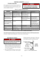
TROUBLE- SHOOTING
Note any optional accessorie s that may be f urnished on
the 7ADTB and review their operation. Refer to any
separate drawings and/or instructions that may be packed
with the 7ADTB. See Table B.
Hazardous voltage capable of causing shock,
burns, or death is used in this switch.
Do not touch the power or load terminals
ofthebypassswitchortransferswitch!
Table B. Trouble-Shooting Checks.
P
R
O
B
L
E
M
CHECK IN NUMERICAL SEQUENCE
P
R
O
B
L
E
M
1OPERATION 2 GEN-SET 3VOLTAGE
Engine–generator set does
not start when the Transfer
Control switch is turned and
held
in Transfer Test position
or when normal source fails.
Hold T ransfer Test switch 15
seconds or the outage must
be long enough to allow for
Feature1Ctimedelayplus
engine cranking and star ting.
Starting control must be in the
automatic position. Batteries
must be charged and
connec ted. Check wiring to
engine starting contacts.
---
Transfer switch does not
transfer the load to the
emergency source after the
engine–generator set starts.
W ait for Feature 2B time delay
to time out.
Generator output circuit
breaker must be closed.
Generator frequency must be
at least 95% of nominal (57 Hz
for a 60 Hz system.) *
Voltmeter should read at least
90% of nominal phase to
phase voltage between
terminals EA and EC (or EL1
and EL2 for 2 po le switches)*
Transfer switch does not
transfer the load to normal
source when normal returns
or when the Transfer Control
switch is released.
W ait for Feature 3A time delay
to time out.
---
Voltmeter should read at least
90% of nominal phase to
phase voltage between
terminals NB and NC, NC and
NA , and NA and NB (or NL1
and NL2 for 2 po le switches).
Gen. does not stop after load
retransfer to normal source.
W ait for Feature 2E time delay
to time out.
Starting control must be in the
automatic position.
---
Load Disconnect Active light
comes on.
W ait for load disconnect time
delay to time out.
Explanation: Transfer switch in delayed transition transfer mode.
Load disconnect time delay is adjustable from 0 to 5 min. 59 sec.
Load Disconnect Active light
staysonlongerthan6min.
Check load disconnect time
delay setting. Call ASI.
Explanation: Transfer switch contacts are open longer than 5
min. 59 sec (maximum setting). Load remains disconnected.
* These are factory settings. Refer to Controller’s User’s Guide.
If the problem is isolated to circuits on the controller or the transfer switch, call your local ASCO Power Technologies
sales office or ASI: in the United State s, call 1–800–800–2726 or in Canada call 1–888–234–2726. Furnish the Serial No.,
Catalog No., and Bill of Material (BOM) No. from the transfer switch nameplate.
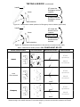
MAINTENANCE HANDLE
Bypass and isolate the Transfer Switch before
using the maintenance handle! See pages
3–1 through 3–4. Remove the maintenance
handle after using it; store it inside.
1. By pass, isolate, and withdraw the transfer switch
(pages 3–1 through 3–4). The n locate and remove the
maintenance handle from the clip (inside lower left
side). Insert the handle onto the shaft o n the left side
of the operator of the transfer switch See Figures
2–1, 2–2, 2–3 and Table C.
2. Move the maintenance handle up or down as shown
to manually operate the transfer switch. Operate
both upper and lower contact shafts. Observe the
window indi cators (right side). Remove the mainte-
nance handle and store it on the lower left side.
window
indicators
O is open
C is closed
contact
position
indicators
(right side)
Emergency contacts
(upper shaft)
Normal contacts
(lower shaft)
Figure 2–1. Contact position indicators.

TESTING & SERVICE
(continued)
2--3
handle
shaft extension
frame
UP opens the
Emergency source
contacts
DOWN closes the
Emergency source
contacts
UPPER SHAFT
Figure 2–2. Maintenance handle operation for Emergency source contacts (upper sha ft).
handle
shaft externsion
frame
UP closes the
Normal source
contacts
DOWN opens the
Normal source
contacts
LOWER SHAFT
Figure 2–3. Maintenance handle operation for Normal source contacts (lower shaft).
Table C. Maintenance handle positions.
ALL POWER MUST BE OFF !
Transfer Switch Position Interlocked Shafts Maintenance Handle Shaft Indicators
N
o
r
m
a
l
E
t
t
h
f
t
shaft
extension
up
E=O
upper contacts open
N
orma
l
N
link
contact sha
f
ts
shaft
extension
up
N=C
lower contacts closed
Load
E
up
E=O
upper contacts open
L
o
a
d
Disconnected
N
down
N=O
lower contacts open
E
m
e
r
g
e
n
c
y
E
down
E=C
upper contacts closed
E
mergency
N
down
N=O
lower contacts open
* Link between contac t shafts prevents clo sing bot h N and E contacts . The shaft extens ion and co ntact shaft turn in oppos ite
directio ns thro ugh a cam–follower mechanism. If Normal and Emergency co nnectio s are reversed this operat ion is also reversed.

SECTION 3 BYPASSING & ISOLATING
3 --- 1
Figure 3–1. Status lights and Engine Control.
TRANSFER SWITCH
CONNECTED TO NORMAL
CONNECTED TO EMERGENCY
Lower red light is on if
Transfer Switch is on
Emergency.
Upper green light is on
if Transfer Switch is on
Normal.
Figure 3–2. Status lights for Transfer Switch main
contact position.
TS CONNECTEDUpper amber light
should be on.
TS TEST
TS ISOLATED
Figure 3–3. Status lights for Transfer Switch isolation
contact position.
BYPASSING THE ATS*
This procedure explains how to Bypass the closed
transfer switch contacts. Bypassing is required before the
Transfer Switch can be tested or isolated. The Bypass
Switch Handle must be in the OPEN position (green
window indicator) and the Isolation Handle must be in
the CONN [connected] position (window indicator). The
TS Connected light must be on. See Figures 3–1, 3–2, 3–3.
You can only bypass to the same source
that the Transfer Switch is connected.
Solenoid interlock prevents incorrect operation.
1. Observe which Transfer Switch Connected To light is
on (Normal or Emergency) on the door. This is the
position of the transfer switch (se e Figure 3–2).
2. Follow the directions on next page to Bypass to the
same source as connected to transfer switch
(select
Normal or Emergency).
Window indicator
shows green
when the ATS is
not
bypassed.
Window indicator
shows yellow
when ATS is
bypassed to
Emergency.
Window indicator
shows yellow
when ATS is
bypassed to
Normal.
Figure 3–4. Bypass Handle and
three position window indicators.
NOTE: The 7ATB contains mechanical (window)
indicators for the bypass switch and transfer switch
positions in addition to the LED status lights.
Allowable Positions of the Bypass Switch
in relation to Positions of the Transfer Switch
(with Isolation Handle in the Conn [connected]
position and TS Connected light on)
Transf er Switch
Bypass Switch
canbeineither
If Transfer Switch is in
Normal position.
Open or Normal
If Transfer Switch is in
Emergency position.
Open or Emergency

BYPASSING & ISOLATING
(continued)
3 --- 2
To Bypass Normal Source* To Bypass Emergency Source*
(Load connected to Normal Source)
The Transfer Swit ch Connected To Normal light is on
and Transfer Switch Connected To Emergency light is off.
(Load connected to Emergency Source)
The Transfer Switch Connected To Emergency light is on
and Transfer Switch Connected To Normal light is off.
Push in
thehandleand
turn it counterclockwise.*
Turnthehandleclockwise.*
Push in* the Bypass Handle all the way , then turn it
counterclockwise until Bypass Switch Position shows
closed on NORMAL (yellow window indicator). The
green light Bypassed to Normal will come on and the
amber light Not In Automatic will flash.
E
L
N
Push in
Bypass
Handle
and
turn it
counter-
clockwise.
ATS
Bypass Switch
Figure 3–5. Bypass to Normal diagram.
BYPASS SWITCH
BYPASSED TO NORMAL
BYPASSED TO EMERGENCY
Upper green
light comes on
Lower window indicator
NORMAL shows yellow
Figure 3–6. Status light and window indicator for
Bypassed to Normal Source.
Turn* the Bypass Handle clockwise until Bypass Switch
Position shows closed on EMERGENCY (yellow window
indicator). The red light Bypassed to Emergency will come
on and the amber light Not In Automatic will flash.
E
L
N
ATS
Bypass Switch
Turn
Bypass
Handle
clock-
wise.
Figure 3–7. Bypass to Emergency diagram.
BYPASS SWITCH
BYPASSED TO NORMAL
BYPASSED TO EMERGENCY
Lower red
light comes on
Upper w indow indicator
EMERGENCY shows yellow
Figure 3–8. Status light and window indicator for
Bypassed t o Emergency Source.
The automatic transfer switch can now be put in the TEST or OPEN position. See ISOLAT ING on page 3–3.
*NOTE: When Accessory 40*B (reversed Normal & Emergency connections)
is specified, the handle operation is reversed. Follow instructions on the door.

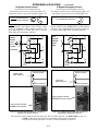
BYPASSING & ISOLATING
(continued)
3 --- 3
ISOLATING THE ATS
Isolating is required before any servi ce work can be
performed on the automatic transfer switch (ATS). Refer
to Figures 3–9, 3–10, 3–11, and 3–12.
1. Bypass the closed
automatic transfer swi tch contact s.
See BYPASSING on pages 3–1 and 3–2.
2. Turn the Isolation Handle counterclockwise (approx.
8 turns) until window shows TEST.TheTS Test amber
lightshouldcomeon.TheATScanbetestednow
without load int erruption (see p age 2–1).
E
L
N
Automatic Transfer Switch
Bypass Switch
Turn crank
counter-
clockwise
until
window
shows
TEST.
Figure 3–9. CONNECTED to TEST position.
TS CONNECTED
Middle amber light
should be on.
TS TEST
TS ISOLATED
position
window
CONN
TEST
ISOLATE
counterclockwise – draws
out the transfer switch
Figure 3–10. Isolation Handle turned to TEST.
NOTE: In the TEST position the transfer
switch solenoid operator circuit is energized
through secondary disconnects.
Hazardous voltage capable of causing
electrical shock, burns, or dea th;
do not touch any control circuit terminals.
3. Continue turningIsolation Handle counterclockwise
(approx. 6 turns) until the window shows ISOLATE.
The TS Isolated amber light should come on.
E
L
N
Turn crank
counter-
clockwise
until
window
shows
ISOLAT E.
Automatic Transfer Switch
Bypass Switch
Figure 3–11. TEST to ISOLAT E position.
TS CONNECTED
Lower amber light
should be on.
TS TEST
TS ISOLATED
position
window
CONN
TEST
ISOLATE
counterclockwise – draws
out the transfer switch
Figure 3–12. Isolation Handle turned to ISOLATE.

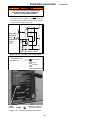
BYPASSING & ISOLATING
(continued)
3 --- 4
4. Open the lower enclosure door. Pull out both left and
right side rails then use the two tab handles to roll out
the transfer switch. It can be safely inspected in this
position. The transfer switch can a lso be removed for
easi er maintenance operati ons. See Figure 3–13.
Hazardous voltage capable of causing
electrical shock, burns, or dea th;
do not touch any control circuit terminals.
right rail
left rail
tab
handles
Figure 3–13.Transfer switch isolated
and pulled out for inspection.
See page 2–2 for maintenance handle use. A lift ing y o ke
812053 is available to facilitate lifting by using an
overhead crane or similar equipment. See WARNING.
The Transfer Switch weighs about 150 lbs.
dependi ng upon the number of poles. Use lifti n g
devi ce 812053 or oth er devic e capable of lift i ng
this weight to avoid personal injury or equipment
damage. Two persons are recommended.
Contact Inspecti on
Contact condition should be checked annually.
Discoloration is normal. Do not file contacts
because it wastes material. Instead use light emery
paper to clean up the contact surfaces. The
non–replaceable main contacts are designed to last
thelifeofthetransferswitch.
To prevent the possibility of fatal electrical
shocks and burns, bypass, isolate, and withdraw
the transfer switch before working on it.
1. Deenergi ze transfer switch (pages 3–1 thru 3–4)
Bypass, isolate, and withdraw transfer switch.
Use a voltmeter to verify that no electrical
power is present at the transfer switch terminals.
2. Use the maintenance handle (page 2–2).
Open the contacts that will be inspected by using
the detachable maintenance handle.
3. Remove the barrier (Figure 3–14).
Use a phillip screwdriver to loosen (ccw) four or
six captive round–head screws holding the
barrier to the arc chutes. Then pul l the barrier
straight outward to remove it.
4. R ein stall the barrier.
Install th e barrier over the arc chu t es. Use a
ph illip s screwd river to tigh t en (cw ) the fou r or six
roun d – h ead screws to secure the barrier to the arc
chute insulator nuts. See Figure 3–14.
Figure 3–14. Barrier removal.

BYPASSING & ISOLATING
(continued)
3 --- 5
RETURN TO SERVICE
This procedure explains how to return the automatic
transfer switch (ATS) to service after inspection and
maintenance. Observe the Bypass Switch Position indica-
tor and lights).
1. Use t he two tab handles to roll the transfer switch
into the enclosure (isolation contacts facing inward)
until the crank bearings stop against the draw–in
plates. Then push in both side rails and close the
enclosure door.
right rail
left rail
tab
handles
Figure 3–15.Transfer switch isolated
and pulled out for inspection.
Close the enclosure door to prevent personal
injury in case of electrical system fault.
2. Turn Isolation Handl e clockwise (approx. 6 turns) until
the wind ow shows TEST and TS TEST l ight com es on.
E
L
N
Turn crank
clockwise
until
window
shows
TEST.
Automatic Transfer Switch
Bypass Switch
Figure 3–16. ISOLATE to TEST position.
TS CONNECTED
Middle amber light
should come on.
TS TEST
TS ISOLATED
position
window
TEST
clockwise – draws in
the transfer switch
Figure 3–17. Isolation Handle turned to TEST.
3. The AT S can be t ested now without load interruption
(see page 2–1).
Solenoid interlock prevents you from closing
the isolation contacts until the ATS is in the
same
position as the Bypass Switch.
4. Observe which Bypass Switch Position window indica-
tor is yellow (NORMAL or EMERGENCY)atthe
Bypass Switch Handle. This indicates the source
connected to the load.
5. Observe which Transfer Switch Connected To light is
on (Normal or Emergency) on the door. This is the
positionof the TransferSwitch. If it is not
in the same
position as the Bypass Handle change the position of
the Transfer Switch as follows:
To change the position of transfer switch
Operate to NORMAL Operate to EMERGENCY
Turn Transf er Contro l
switch to Retransfer
Delay Bypass.
Turn Transf er Contro l
switch to Transfer Test
(hold 15 seconds).*
Connected To Normal
light should come on.
Connected To Emergency
light should comes on.
* If Feature 2B time delay is used, there will be a delay
before transfer to Emergency.
NOTE: With Normal available, the automatic transfer
switch will not stay in the emergency position unless
Feature 3A time delay is used (at least 30 seconds).

BYPASSING & ISOLATING
(continued)
3 --- 6
Do no t close the isolation contacts unless
the Transfer Switch (ATS) and Bypass
Switch a re in the same position!
6. When the transfer switch i s in the same
position as
the Bypass Switch handle, continue turning the
Isolation Handle clockwise (about 8 turns) until the
window shows CONN (connected).
E
L
N
Automatic Transfer Switch
Bypass Switch
Turn crank
clockwise
until
window
shows
TEST.
Figure 3–18. TEST to CONN (connected) position.
TS CONNECTED
Upper amber light
should be on.
TS TEST
TS ISOLATED
position
window
CONN
clockwise – draws in
the transfer switch
Figure 3–19. Isolation Handle turned to CONN.

BYPASSING & ISOLATING
(continued)
3 --- 7
RETURN TO SERVICE continued*
This procedure explains how to return the Bypass Switch
Handle to the OPEN position. The Bypass Handle must
be in the CLOSED position (yellow indicator on NOR-
MAL or EMERGENCY) and the Isolation Handle must
be in the CONN position (window). See Figures 3–20,
3–21, and 3–22.
You can only bypass to the same source
that the A TS is connected. Solenoid
interlock prevents incorrect operation.
1 Observe which Bypass Switch Position indicator is
yellow (NORMAL or EMERGENCY)attheBypass
Switch Handle. T his indicates the source connected
to the load.
2 Un–Bypass to same source as the Bypass
Switch
Position
as follows (select Normal or Emergency).
Window indicator
shows green
when the ATS is
not
bypassed.
Window indicator
shows yellow
when ATS is
bypassed to
Emergency.
Window indicator
shows yellow
when ATS is
bypassed to
Normal.
Figure 3–20. Bypass Handle and position indicators.
To Un–Bypass Normal S ource* To Un–Bypass Emergency Source*
(Load connected to Normal Source)
The Transfer Swit ch Connected To Normal light is on
and Transfer Switch Connected To Emergency light is off.
(Load connected to Emergency Source)
The Transfer Switch Connected To Emergency light is on
and Transfer Switch Connected To Normal light is off.
Turnthehandleclockwise.* Turnthehandlecounterclockwise.*
Turn* the Bypass Handle clockwise until the Bypass
Switch Position shows OPEN (green window i ndicator).
The Bypassed to Normal lightshouldgooffandtheNot
In Automatic light should go off.
E
L
N
Turn
Bypass
Handle
clockwise.
ATS
Bypass Switch
Figure 3–21. Un–Bypass Normal diagram.
Turn* the Bypass Handle counterclockwise until t he
Bypass Switch Position shows OPEN (green window
indicator). The Bypassed to Emergency light should go off
and the Not In Automatic light should go off.
E
L
N
ATS
Bypass Switch
Turn
Bypass
Handle
counter-
clockwise.
Figure 3–22. Un–Bypass Emergency diagram.
The Automatic Transfer & Bypass–Isolation Switch should be left in this position.
*NOTE: When Accessory 40*B (reversed Normal & Emergency connections) is specified,
the handle push–pull operation is reversed. Follow instructions on the door.

INDEX
Printed in U.S.A.
Copyright 2007 ASCO Power Technologies, L.P.
A
auxiliary circuits, 1–2
B
barriers, interphase, 3–4, 3–5
bypassing the ATS, 3–1, 3–2
C
catalog number, 1–1
cleaning, 2–1
connections
power, 1–1
contact inspecti on, 3–4, 3–5
controller
disconnecting, 2–1
see Controller User’s Guide
D
delayed transition transfer, 1–4
see Controller User’s Guide
E
electrical operation, 1–4
Emergency Source Accepted light,
1–3
engine starting contacts, 1–2
F
foundation, 1–1
frequency, generator, 2–2
functional test , 1–2, 1–3, 1–4
H
harness, 1–2
disconnect plugs, 2–1
HELP
customercare@asco.com
800–800–2726 (ASCO)
I
indicat ors, contact position, 2–2, 2–3
inspection, 3–1
installation, 1–1
interlocked weights, 2–3
interphase barriers, 3–4, 3–5
isolating the ATS, 3–3, 3–4
L
lifting device, transfer swi tch, 3–4
lights, 1–2, 1–3, 3–1, 3–2, 3–3
load connected to emergency, 1–3
load connected to normal, 1–3
Load Disconnect Active light, 1–4
lubrication, 2–1
M
maintenance, preventive, 2–1
maintenance handle, 2–3
warning, 2–3
manual load transfer, 2–3
warning, 2–3
N
nameplate, 1–1
Normal Source Accepted light, 1–3
O
operation
electrical, 1–4
manual, 2–3
warning, 2–3
optional accessories
see Controller User’s Guide
P
parts, 2–1
phase rotation check, 1–3
preventive maintenance, 2–1
problem, 2–2
R
rating label, cover
replacement parts, 2–1
return to service, 3–5, 3–6, 3–7
S
service
ASCOServices,Inc.(ASI),2–1
settings
see Controller User’s Guide
T
test, functional, 1–2, 1–3, 1–4
testing power cables, 1–1
time delays, 2–1
see Controller User’s Guide
Transfer Control selector switch
Retransfer Delay Bypass, 1–3
Transfer Test, 1–3
Transfer Switch Connected To
Emergency light, 1–3
Transfer Switch Connected To
Normal light, 1–3
transfer test, 1–4, 2–1
transfer to emergency, 1–4, 2–1
transfer to normal, 1–4, 2–1
troubleshooting, 2–2
V
voltage checks, 1–3
voltage, pickup and dropout settings
see Controller User’s Guide
-
 1
1
-
 2
2
-
 3
3
-
 4
4
-
 5
5
-
 6
6
-
 7
7
-
 8
8
-
 9
9
-
 10
10
-
 11
11
-
 12
12
-
 13
13
-
 14
14
-
 15
15
-
 16
16
-
 17
17


ASCO POWER TECHNOLOGIES 7000 Series User manual
- Category
- Power supply units
- Type
- User manual
- This manual is also suitable for
Ask a question and I''ll find the answer in the document
Finding information in a document is now easier with AI
Other documents
-
Emerson 7000 SERIES 7ADTB User manual
-
-
Trendnet Series 300 User manual
-
-
-
-
-
-
-
Schneider Electric 300 Series User manual