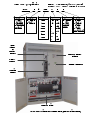
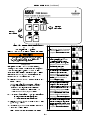
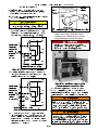
Emerson 7ATB Automatic Transfer & Bypass-Isolation Switch is an automatic transfer switch that can be used to provide backup power in the event of a power outage. It consists of an upper bypass-isolation switch, a lower transfer switch, a monitoring and transfer controller, and door-mounted controls. The Emerson 7ATB has a variety of features that make it a versatile and reliable choice for backup power applications, including:
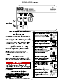
- Automatic transfer: The Emerson 7ATB will automatically transfer power from the normal source to the emergency source in the event of a power outage.
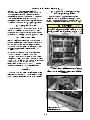
- Bypass operation: The bypass-isolation switch allows for maintenance or repairs to be performed on the transfer switch without interrupting power to the load.
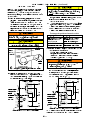
Emerson 7ATB Automatic Transfer & Bypass-Isolation Switch is an automatic transfer switch that can be used to provide backup power in the event of a power outage. It consists of an upper bypass-isolation switch, a lower transfer switch, a monitoring and transfer controller, and door-mounted controls. The Emerson 7ATB has a variety of features that make it a versatile and reliable choice for backup power applications, including:
- Automatic transfer: The Emerson 7ATB will automatically transfer power from the normal source to the emergency source in the event of a power outage.
- Bypass operation: The bypass-isolation switch allows for maintenance or repairs to be performed on the transfer switch without interrupting power to the load.


-
 1
1
-
 2
2
-
 3
3
-
 4
4
-
 5
5
-
 6
6
-
 7
7
-
 8
8
-
 9
9
-
 10
10
-
 11
11
-
 12
12
-
 13
13
-
 14
14
-
 15
15
-
 16
16


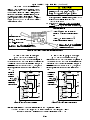
Emerson 7ATB Automatic Transfer & Bypass-Isolation Switch is an automatic transfer switch that can be used to provide backup power in the event of a power outage. It consists of an upper bypass-isolation switch, a lower transfer switch, a monitoring and transfer controller, and door-mounted controls. The Emerson 7ATB has a variety of features that make it a versatile and reliable choice for backup power applications, including:
- Automatic transfer: The Emerson 7ATB will automatically transfer power from the normal source to the emergency source in the event of a power outage.
- Bypass operation: The bypass-isolation switch allows for maintenance or repairs to be performed on the transfer switch without interrupting power to the load.
Ask a question and I''ll find the answer in the document
Finding information in a document is now easier with AI
Related papers
Other documents
-
American Pro Decor 5APD10783 Installation guide
-
Trendnet Series 300 User manual
-
Schneider Electric 300 Series User manual
-
 MK Diamond Products ATS Stand Owner's manual
-
Simplicity 071098 User manual
-
GE General Electric Switch ZTSCT User manual
-
-
ABB Zenith MX250 Operation and Maintenance Manual
-
Simplicity 071112 User manual
-
Eaton Magnum Transfer Switch User manual
