Quincy Compressor QR-25 210 User manual

Category
Air compressors
Type
User manual
This manual contains important safety information and must be
carefully read in its entirety and understood prior to installation
by all personnel who install, operate and/or maintain this product.
Product warranty information is available at www.quincycompressor.com/about/warranties
Manual No. 52201-107
December 2012 Edition
QR-25
®
Series
Instruction Manual
QR-25 Series Quincy Compressor
52201-107, December 2012 ii 3501 Wismann Lane, Quincy IL - 62305-3116
Contents
SECTION 1 SAFETY
Safety First .............................................................................................................................................. 1
Summary of Changes .............................................................................................................................. 3
SECTION 2 SYSTEM DYNAMICS
Description & Application ....................................................................................................................... 4
Principles of Compression Cycles ........................................................................................................... 4
Principles of Lubrication Systems .......................................................................................................... 5
Principles of Cooling Systems ................................................................................................................. 5
Principles of Dryers & Filters ................................................................................................................. 5
Control Components ................................................................................................................................ 5
Control Versions ...................................................................................................................................... 5
Specifications ........................................................................................................................................... 7
SECTION 3 INSTALLATION
Receiving Delivery ................................................................................................................................... 8
Freight Damage ....................................................................................................................................... 8
Location .................................................................................................................................................... 9
Electrical Supply Requirements ........................................................................................................... 10
Mounting ................................................................................................................................................ 10
System Components .............................................................................................................................. 11
Wiring Schematics ................................................................................................................................. 12
Induction System ................................................................................................................................... 14
Compressed Air Discharge System ....................................................................................................... 15
SECTION 4 START-UP & OPERATION
Pre-Starting Checklist........................................................................................................................... 20
Initial Starting & Operating ................................................................................................................. 21
Daily Starting Checklist........................................................................................................................ 21
SECTION 5 MAINTENANCE & LUBRICATION
Stopping for Maintenance ..................................................................................................................... 23
Maintenance Schedule .......................................................................................................................... 23
Maintenance Schedule Checklist Sample ............................................................................................ 23
Lubrication ............................................................................................................................................. 24
Pulley / Sheave Alignment & Belt Tension .......................................................................................... 25
Pressure Switch Adjustment................................................................................................................. 27
Reversal of Compressor Rotation ......................................................................................................... 27
Pilot Valve Adjustments ........................................................................................................................ 29
SECTION 6 TROUBLESHOOTING
Troubleshooting ..................................................................................................................................... 30
SECTION 7 REFERENCE INFORMATION
Approximate Capacity Correction for Altitude .................................................................................... 34
Average Intercooler Pressures .............................................................................................................. 35
Decal Locations ...................................................................................................................................... 36
QR-25 Series Quincy Compressor
52201-107, December 2012 1 3501 Wismann Lane, Quincy IL - 62305-3116
SECTION 1 SAFETY
Safety First
At Quincy Compressor safety is not only a primary concern, but a faithfully
performed practice. Beginning with the design stage, safety is built into “The
World’s Finest Compressor”. It is the inten tion of this manual to pass along
the “safety first” concept to you by providing safety precautions throughout
its pages.
“DANGER !”, “WARNING !”, and “CAUTION !” are displayed in large
bold capital letters in the left hand column to call attention to areas of vital
concern. They represent different degrees of hazard seriousness, as stated
below. The safety precaution is spelled out in bold upper and lower case let-
ters in the right hand column.
Immediate hazards which will result in severe personal injury or
death.
Hazards or unsafe practices that could result in personal injury or
death.
Hazards or unsafe practices which could result in minor personal
injury, product or property damage.
Each section of this instruction manual, as well as any instruc tions supplied
by manufacturers of supporting equipment, should be read and understood
prior to starting the compressor. If there are any questions regarding any
part of the instructions, please call your local Quincy Compressor distributor,
or the Quincy Compressor factory before creating a potentially hazardous
situa tion. Life, limb, or equipment could be saved with a simple phone call.
Compressors are precision high speed mechanical equipment requiring
caution in operation to minimize hazard to property and personnel. There
are many obvious safety rules that must be ob served in the operation of this
type of equipment. Listed below are some additional safety precautions that
must be observed.
•Transfer of toxic, dangerous, flammable or explosive substances using Quincy
Compressor products is at the user’s risk.
•All installation, maintenance and repair must be performed by a qualified
technician and/or electrician.
•Turn off and lockout/tagout (per OSHA regulation 1910.147) the main power
disconnect switch before attempting to work or perform any maintenance.
•Wear safety glasses and hearing protection during operation, service and
maintenance procedures.
•Do not attempt to service any part of the unit while it is operating.
WARNING !
CAUTION !
DANGER !
QR-25 Series Quincy Compressor
52201-107, December 2012 2 3501 Wismann Lane, Quincy IL - 62305-3116
•Allow ample time for the compressor to cool before performing service pro-
cedures. Some surface temperatures exceed 350°F when the compressor is
operating.
•Per OSHA regulation 1910.147, relieve the system of all pressure before at-
tempting to service any part of the unit.
•Do not operate the unit with any of its safety guards, shields, or screens
removed.
•Do not remove or paint over any DANGER!, WARNING!, CAUTION!, or
instructional materials attached to the compressor. Lack of information re-
garding hazardous conditions can cause property damage or personal injury.
•Periodically check all pressure relief valves for proper operation.
•Do not rebuild or change the pressure setting of the pressure relief valve, re-
strict the function of the inlet or outlet of the pressure relief valve, or replace
the pressure relief valve with a plug or any device not specifically certified
for this function.
•Do not install a shutoff valve in the compressor discharge line with out first
installing a pressure relief valve of proper size and design between the shutoff
valve and the compressor.
•Do not use plastic pipe, rubber hose, or lead-tin soldered joints in any part
of the compressed air system.
•Alterations must not be made to this compressor without Quincy Compres-
sor’s approval.
•Be sure that all tools, shipping and installation debris have been re moved
from the compressor and installation site prior to starting the compressor.
Do not operate a Quincy Compressor in excess of 250 PSIG unless
it has been tested and certified for high pressure application by
Quincy Compressor prior to shipment.
•High pressure units (pressures exceeding 250 PSIG) require parts certified
for use in high pressure applications. When replacing parts on high pressure
units, please consult the parts manual and use only the part numbers listed
in that manual.
•Do not operate the compressor in excess of the ASME pressure vessel rating
for the receiver or the service rating of the compressor, whichever is lower.
•Make a general overall inspection of the unit daily and correct any unsafe
situations. All fasteners must be kept tight.
•Reckless behaviour of any kind involving compressed air is dangerous and
can cause very serious injury to the participants.
WARNING !
QR-25 Series Quincy Compressor
52201-107, December 2012 3 3501 Wismann Lane, Quincy IL - 62305-3116
•Provisions should be made to have the instruction manual readily available
to the operator and maintenance personnel. If for any reason any part of the
manual becomes illegible or the manual is lost, have it replaced immediately.
The instruction manual should be read periodically to refresh one’s memory.
It may prevent a seri ous or fatal accident.
•Never use a flammable or toxic solvent for cleaning the air filter or any parts.
Air used for breathing or food processing must meet OSHA 29 CFR
1910.134 or FDA 21 CFR 178.3570 regulations. Failure to do so may
cause severe injury or death.
Oil and moisture residue must be drained from the air receiver
daily or after each use. Accumulations of oil residue in the receiver
can be ignited by embers of carbon created by the heat of compres-
sion, causing an explosion, damage to property and injury to per-
sonnel.
When using battery cables to start engine driven units do not use
more than a total of 40 ft. of #4 gauge cable (GND & HOT).
The owner, lessor or operator of any compressor unit manu factured by
Quincy Compressor is hereby warned that failure to ob serve the safety precau-
tions and procedures outlined in this manual may result in serious personal
injury, damage to property, and may void your warranty. Quincy Compressor
must authorize all warranty service. Before contacting your distributor or the
factory, check the maintenance requirements and the troubleshooting guide
for your compressor. Most warranty issues can be resolved by following proper
maintenance procedures.
Quincy Compressor neither states as fact, nor in any way implies that the
above list of safety precautions is an all inclusive list, the observance of which
will prevent all damage to property or injury to personnel.
Every effort has been taken to ensure that complete and correct instructions
have been included in this manual. However, possible product updates and
changes may have occurred since this printing. Quincy Compressor reserves
the right to change specifications with out incurring any obligation for equip-
ment previously or subse quently sold.
Summary of Changes to This Manual
(since previous printing dated October 2004):
· Removed warranty statement and added URL address on front cover for
warranty information available on the Quincy Compressor website
· Added information pertaining to Canadian Standards (CSA)
· Added minimum tank wall thickness information
· Added explanation of tank drain decal
DANGER !
WARNING !
CAUTION !
QR-25 Series Quincy Compressor
52201-107, December 2012 4 3501 Wismann Lane, Quincy IL - 62305-3116
SECTION 2 SYSTEM DYNAMICS
Description & Applica-
tion
The Quincy Compressor QR-25
Series consists of heavy duty
indus trial, belt driven, single or
two stage compressors. Single
stage compressors are capable
of delivering up to 100 PSIG
continuously. Some single
stage compressors are capable
of delivering up to 150 PSIG
intermittantly (with proper
controls and modifica tions). Two
stage compressors can deliver
up to 200 PSIG contin uously,
and up to 250, 350 or 500 PSIG
intermittently depending upon
the model, controls and configu-
ration.
Principles of Compres-
sion Cycles
Single Stage Compressors
During the downstroke of a
single stage compressor, air is
drawn through an intake valve
in the head of the compressor
and into the cylinder. At the
bottom of the stroke, the intake
valve closes and air is trapped in the cylinder. The air is then compressed
in the cylinder during the upstroke of the piston. Total compression, from
atmo spheric pressure to the final discharge pressure, is accomplished in one
stroke of the piston.
Two Stage Compressors
During the downstroke of the piston of a two stage compressor, air is drawn
through an intake valve in the head of the compressor into the low pressure
cylinder and compressed during the upstroke of the piston.
The compressed air is then released through a discharge valve in the head
of the compressor to an intercooler (usually finned tub ing) where the heat
resulting from compression is allowed to dissipate. The cooler compressed air
is then drawn into a second compression cylinder, the high pressure cylinder,
for compression to final pressure.
From there the compressed air is released through a discharge valve to an
air receiver tank or directly to a network of compressed air supply lines. In
one revolution of the crankshaft a compression cycle is completed.
Fig. 2-1 Cross Section of Typical QR-25
2 Stage Pressure Lubricated Cylinder & Crankcase
Pix 1064
QR-25 Series Quincy Compressor
52201-107, December 2012 5 3501 Wismann Lane, Quincy IL - 62305-3116
Principles of Lubrication Systems
Moving parts within the crankcase are supplied with lubrication by a posi-
tive displacement, gerotor type oil pump. Oil is drawn up from the bottom of
the crankcase to the oil pump through an oil sump strainer screen. The oil is
then forced under pressure through the oil filter (if so equipped). Oil travels
under pressure through drilled journals in the crankshaft and connecting rods
to lubricate crankshaft bear ings, connecting rod journals, wrist pin bearings
and the cylinder walls.
Principles of Cooling Systems
Fan blades of the compressor sheave force ambient air across fins of the cylinder
head(s), and intercooler fins of two stage compressors, to cool the compressor.
QR-25 series compressors are normally set up at the factory with a sheave that
turns in a counterclockwise rotation. For special applications, clockwise rota-
tion compressor sheaves are available as optional equipment on some models.
QR-25 series compressors should be operated in temperatures under 104°F.
Principles of Dryers & Filters
Moisture occurs naturally in air lines as a result of compression. Moisture
vapor in ambient air is concentrated when pressurized and condenses when
cooled in downstream air piping. Compressed air dryers reduce the moisture
vapor concentration and prevent water formation in compressed air lines.
Dryers are a recommended companion to filters, aftercoolers, and automatic
drains for improving the productivity of compressed air systems.
Water and moisture vapor removal increases the efficiency of air operated
equipment, reduces contamination and rusting, increases the service life of
pneumatic equipment and tools, prevents air line freeze-ups, and reduces
product rejects.
Control Components
Unloader Towers: Provided as part of the basic compressor when control
version is specified.
Pilot Valve: Used in conjunction with unloader towers when the compressor
is to run continuously and an operating pressure range is to be maintained.
Refer to your parts manual for correct pilot valve, ranges and settings.
Hydraulic Unloader: Used on pressure lubricated compressors to protect
the compressor in the event of a potentially damaging oil pressure drop. Also
ensures that the compressor does not begin to produce compressed air until
there is sufficient oil pressure.
Pressure Switch: Used for start/stop appli cations (usually accompanied by a
hy draulic unloader). The pressure switch detects the demand for compressed
air and allows the unit to start. When the de mand is satisfied, the unit stops.
Control Versions
Various control versions are available for the model QR-25 series compressors.
The control version required is determined by how frequent there is a demand
QR-25 Series Quincy Compressor
52201-107, December 2012 6 3501 Wismann Lane, Quincy IL - 62305-3116
for com pressed air. The idea is to create com pressed air on demand, but
to limit the number of times a motor must start the compressor in a given
time period. To prevent motor burnout, the motor should be limited to no
more than six (6) starts per hour.
Control Version P : Describes a basic compressor with no added control
features.
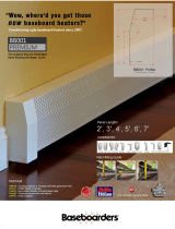
Control Version L : Consists of unloader tower(s)
*
located on the head of
the compres sor, a hydraulic unloader mounted on the bearing carrier, and a
pressure switch. This version is recommended for those applications where
the compressor will not be required to start more than six (6) times per
hour. A compressor equipped with control Version L is sometimes referred
to as a “start/stop machine”
The pressure switch detects the demand for compressed air and allows
the unit to start. When the demand is satisfied, the unit stops.
The hydraulic unloader allows the com pres sor to start in an “unloaded”
state, that is, the compressor starts but does not begin to create compressed
air until oil pressure is established. The hydraulic unloader also guards
against excessive damage in the event of an oil pressure drop.
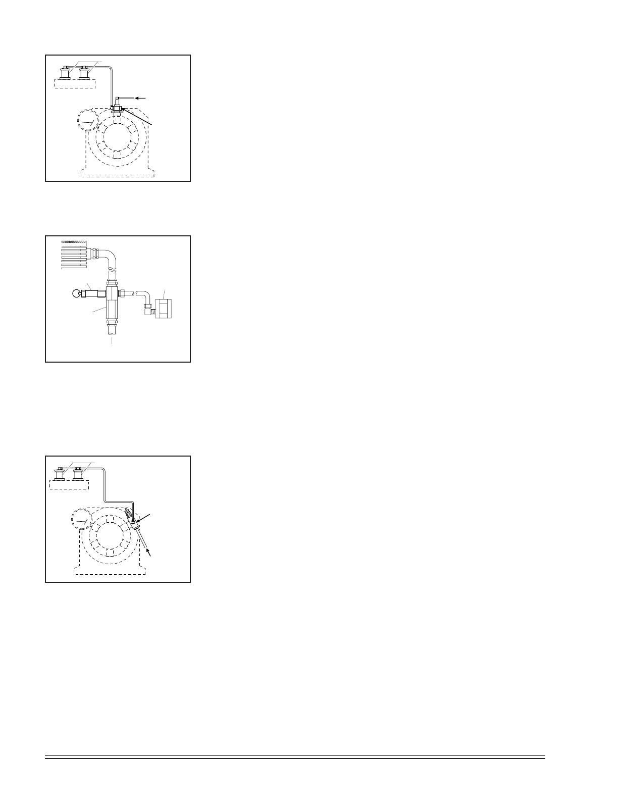
Control Version L Variation: A variation of Control Version L is illus-
trated in Fig. 2-3. It shows how a discharge line check valve, pressure
switch, & pressure relief valve are combined to provide start/stop operation.
Control Version S : This version is best suited for “continuous run” ap-
plications (whenever the compressor must start more than six [6] times
per hour). If the demand for compressed air is continuous and exceeds one
half or more of the compressor’s capacity, Control Version S should be used.
Once the compressor is started, it continues to run until it is manually
turned off. Whenever there is a demand for compressed air, the pilot valve
closes, allowing the un loader in the unloader tower to actuate. At this point,
the compressor starts making com pressed air. As soon as the demand for
com pressed air is met, the pilot valve opens, al lowing air pressure to de-
actuate in the un loader tower. The compressor continues to run but does
not compress air.
Control Version LS: This version consists of a head assembly with un-
loader tower(s)* a pilot valve and a hydraulic unloader. It is usually applied
to gas or diesel engine driven units. Virtually the same as Control Version
S, but with a hydraulic unloader added to protect the compressor in the
event of an oil pressure drop.
Control Version LVD: Unloader tower(s)*, a pilot valve with a manual shut-
off, a hy draulic unloader, a check valve assembly, and a pressure switch make
up the LVD Control Version. This version is recom mended wherever the degree
of demand and usage is variable.
FROM THE
AIR RECEIVER
HYDRAULIC
UNLOADER
Pix 1069
UNLOADER TOWERS
Fig. 2-2 Control Version L
Pix 1069
AUTOMATIC
PRESSURE
SWITCH
CHECK
VALVE
TO
AIR
RECEIVER
Pix 1155
PRESSURE
RELIEF
VALVE
Pix 1155
Fig. 2-3 Control Version L Vari-
ation (Discharge Line Check
Valve & Pressure Switch)
UNLOADER TOWERS
UNLOADER PILOT
(110832 series)
Pix 1071
CONNECT TO
AIR RECEIVER
WITH A MINIMUM
OF 3/8" O.D.
COPPER TUBING.
Pix 1071
Fig. 2-4 Control Version S
*1, 2, or 4 unloader towers are employed depending upon the model of compressor.
QR-25 Series Quincy Compressor
52201-107, December 2012 7 3501 Wismann Lane, Quincy IL - 62305-3116
**Maximum continuous pressure is indicated on left side, maximum intermittent high pressure on right side.
High pressure basics required for pressures above 250 PSIG applications.
The manual shutoff allows for the selec tion of either “start/stop” or “con-
tinuous run” control. In either situation, the hydraulic unloader protects the
compressor from excessive damage caused by a drop in oil pressure.
Specifications
Bore(s) RPM Maximum
Model Stroke LP - HP Range PSIG**†
210 2 2
1
/2 400-1000 100/150
216 2
1
/2 3 400-900 100
240 3 4 400-900 100
270 4 4
1
/2 400-900 100
4125 4 4
1
/2 400-900 100
310 2
1
/2 3
1
/2 - 2 400-900 200/500
325 3 4
1
/2 - 2
1
/2 400-900 200/500
340 3
1
/2 5
1
/4 - 3 400-900 200/500
350 3
1
/2 6 - 3
1
/4 400-900 200/350
370 4 6 - 3
1
/4 400-1070 200/250
390 4 7
1
/2 - 4 400-950 200/250
5120 4 6 - 3
1
/4 400-1050 200/250
QR-25 Series Quincy Compressor
52201-107, December 2012 8 3501 Wismann Lane, Quincy IL - 62305-3116
SECTION 3 INSTALLATION
Receiving Delivery
Immediately upon receipt of compressor equipment and prior to completely
uncrating, the following steps should be taken:
Step 1) Inspect compressor equipment for damage that may have occurred
during shipment. If any damage is found, de mand an inspection
from the carrier. Ask the carrier how to file a claim for shipping
damages. (Refer to SECTION 3, Freight Damage for complete
details.) Shipping damage is not covered by Quincy Com-
pressor warranty.
Step 2)
Insure that adequate lifting equipment is available for moving
the compressor equipment.
Improper lifting can result in component or system damage, or
personal injury. Follow good shop practices and safety procedures
when moving the unit.
Step 3) Read the compressor nameplate to verify the model and size or-
dered.
Step 4) Read the motor nameplate to be sure the motor is compatible with
your electrical conditions (volts, phase, hertz). NOTE: If voltage
drops below 207 volts, use a 200 volt motor. Do not substi-
tute with a triple voltage (208/230-460) 3 phase motor.
Step 5) Read the pressure relief valve nameplate to be sure it does not
exceed the working pressure shown on the compressor or any other
component in the system.
Step 6) Read and understand the safety precautions contained
within this manual. The successful and efficient operation of
compressor equipment depends largely upon the amount of care
taken to install and maintain the equipment. Quincy Compressor
strongly recommends that any or all person(s) in charge of install-
ing, maintaining, or servic ing one of our compressors read and
understand the entire contents of this manual in order to perform
such duties safely and efficiently.
Freight Damage
It is extremely important that you examine every carton and crate as soon as
you receive it. If there is any obvious damage to the shipping container, have
the delivering carrier sign the freight bill, noting the apparent damage, and
request a damage report.
If concealed damage is discovered at a later date, the carrier must
be notified within 15 days of initial receipt of freight. Concealed ship-
ping damage is not covered by Quincy Compressor Warranty. Contact
the carrier as soon as possible, giving them an opportunity to inspect the ship-
CAUTION !
QR-25 Series Quincy Compressor
52201-107, December 2012 9 3501 Wismann Lane, Quincy IL - 62305-3116
ment at the premises where the delivery was made. Do not move the damaged
freight from the premises where the original delivery was made. Retain all
containers and packing for inspection by the carrier.
A claim form can be requested from the carrier: Standard Form for Pre-
sentation of Loss and Damage Claims (form # 3208). Your claim will need to
be substantiated with the following documents:
a.) form #3208
b.) original bill of lading
c.) original paid freight bill
d.) original invoice or certified copy
e.) other particulars obtainable in proof of loss or damage (photos, dam-
age inspection, etc.)
The proper description and classification of our product in the National
Motor Freight Classification 100-H, contained in item 118100, reads as fol-
lows: Compressors, air, or air ends: with or without air tanks, hose or nozzles,
mounted or not mounted.
We suggest that these instructions be circulated to your shipping and
receiving personnel.
Location
Quincy air compressors must be installed and operated in a secure, upright
position in an area that is clean, dry, well lighted, adequately ventilated and
not closer than 24 inches to a wall or another compressor. (Note: A gas engine
will produce carbon monoxide; always provide adequate ventilation!) Inspec-
tion and mainte nance checks are required daily. Therefore, sufficient space
needs to be provided around the compressor for safe and proper in spection,
cleaning, and maintenance.
Ample circu la tion of air must be provided across the compressor cylinders,
heads and cooler (if so equipped). Do not allow hot air from additional equip-
ment to blow towards the compressor unit. If at all possible, the pulley drive
system (i.e. motor pul ley, compressor sheave, belts and guard) should be located
next to a wall to minimize any danger created by the drive system while the
compressor is operating.
QR-25 series compressors should be operated in temperatures under 104°F.
In cold cli mates, compressors should be installed in a heated building.
Do not operate this compressor in ambient temperatures lower
than -15° F. A crankcase heater is recommended for a compressor
that is to operate in temperatures under 32° F.
Under no circumstances should a compressor be used in an area
that may be exposed to toxic, volatile, or corrosive atmo sphere. Do
not store toxic, volatile, or corrosive agents near the compressor.
Noise
Noise is a potential health hazard that must be considered. There are federal
CAUTION !
WARNING !
QR-25 Series Quincy Compressor
52201-107, December 2012 10 3501 Wismann Lane, Quincy IL - 62305-3116
and local laws governing acceptable noise levels. Check with local officials for
specifications.
Excessive noise can be effectively reduced through various meth ods. Total
enclosures, intake silencers, baffle walls, relocating or iso lating the compressor
can reduce noise levels. Care must be taken when constructing total enclosures
or baffle walls. If not properly constructed or positioned, they could contribute
to unacceptable noise levels or over heating. Consult your local Quincy Com-
pressor distributor if assis tance is required.
Unusual noise or vibration indicates a problem. Do not operate the
compressor until the source has been identified and corrected.
Electrical Supply Requirements
The electrical installation of this unit must be performed by a qualified electri-
cian in accordance with the National Electrical Code (NEC) or the Canadian
Electrical Code (CEC), the National Electrical Safety Code (NESC), OSHA
and/or state and local codes. Failure to abide by the national, state and local
codes may result in physical harm and/or property damage.
Before installation, the electrical supply must be checked for adequate wire
size and transformer capacity. A suitable circuit breaker or fused disconnect
switch should be provided. When a 3 phase motor is used to drive a compres-
sor, any unreasonable voltage imbalance between the legs must be eliminated
and any low voltage corrected to prevent excessive current draw. Note: This
unit must be grounded.
High voltage may cause personal injury or death. Disconnect and
lockout/tagout per OSHA regulation 1910.147 all electrical power
supplies before opening the electrical enclosure or servic ing.
Never assume a compressor is safe to work on just because it is not
operating. It could restart at any time. Follow all safety precau-
tions outlined in SECTION 5, Stopping For Maintenance.
NEMA electrical enclosures and components must be appropriate
to the area installed.
Overload Relay
An overload relay monitors the compressor motor electrical current and turns
the compressor motor off when an overload is sensed. It is mounted on the
bottom of the motor starter. The overload relay is designed for motors with a
1.15 service factor. The overload relay setting should be adjusted to the mo-
tor nameplate amp rating. If the motor has a service factor rating other than
1.15, the overload relay setting must be adjusted to compensate. Contact your
Quincy distributor for assistance.
Overload relays are designed to protect the motor from damage
due to motor overload. If the overload relay trips persistently, DO
NOT CONTINUE TO PUSH THE RESET BUTTON! Contact your lo-
cal Quincy distributor for assistance.
CAUTION !
DANGER !
WARNING !
CAUTION !
CAUTION !
QR-25 Series Quincy Compressor
52201-107, December 2012 11 3501 Wismann Lane, Quincy IL - 62305-3116
HORIZONTAL TANK UNITS
ANCHORED
VERTICAL TANK UNITS
ANCHORED
HORIZONTAL TANK UNITS
UNANCHORED
1/2” locknut
1/2” at washer
tank foot
isolator backing plate
1/2” x 2” bolt
isolator
1/2” locknut
1/2” at washer
tank foot
isolator backing plate
isolator
1/2” oor stud
(provided by customer)
1/2” oor stud
(provided by customer)
tank foot
1/2” locknut
1/2” at washer
Fig. 3-1 Isolator Installation for
Unanchored or Anchored Receivers
Mounting
Proper mounting of Quincy compressor units is crucial to the safe operation
and longevity of the equipment. The installation requires a flat and level
concrete floor or pad (for mobile units see Mounting Mobile Units). Satis-
factory results can usually be obtained by mounting horizontal tank units on
vibration isolators available from your local Quincy distributor. All vertical
tank units must be anchored! Quincy recommends that all vertical tank
units be mounted as indicated without
isolators. Refer to Fig. 3-1, Isolator Instal-
lation for Unanchored or Anchored
Receivers.
State or local codes may mandate that
the unit be bolted to the floor. In this case
the unit must be leveled and bolted making
absolutely certain the feet are not stressed
in any manner. Leave the locknut loose!
Uneven feet drawn tightly to the concrete
pad will cause severe vibrations resulting
in cracked welds or fatigue failure. The
customer is responsible for pro viding a
suitable foundation & isolator mounting
where necessary.
Mounting Mobile Units
Units mounted to truck beds should be fas tened in such a way so as not to
create any stress to the air receiver tank. Truck beds, characteristically, have
a tendency to flex and could cause damage to the receiver tank if the tank is
fastened directly to the truck bed. It is the User’s responsibility to provide an
adequate means of fas tening the unit in these applica tions.
Do not operate this compressor more than 15° off level or move it
while it is operating.
System components
Efficiency and safety are the primary concerns when selecting compo nents
for compressed air systems. Products of inferior quality can not only hinder
performance of the unit, but could cause system failures that result in bodily
harm or even death. Select only top quality compo nents for your system. Call
your local Quincy distributor for quality parts and professional advice.
Drive Pulleys / Sheaves
Various pulley and sheave combinations are available to obtain the de sired air
pressure and delivery rate of your compressor. Consideration must be given
to these combinations to ensure that the motor is not over loaded by operating
above or below the designed speed range.
Whatever combination is employed, the drive pulleys & com pressor sheaves
must be properly aligned and drive belt tension set to specifica tions (refer to
SECTION 5, Pulley / Sheave Alignment & Belt Tension). Improper pul-
ley/sheave alignment and belt ten sion can cause motor overloading, excessive
vibration, and prema ture belt and/or bearing failure.
CAUTION !
QR-25 Series Quincy Compressor
52201-107, December 2012 12 3501 Wismann Lane, Quincy IL - 62305-3116
3 Phase Magnetic Motor Starter With Automatic Start / Stop Control
Wiring Schematic WP1744A
Magnetic Starter
Contactor
Overload
Relay
Connect incoming power lines
at screw terminals L1, L2 & L3.
CAUTION !
Verify all wires are secure
and fasteners are torqued
before connecting power to
the unit.
All wires are red unless otherwise specied.
Dashed lines represent wires supplied by others.
At Installation, the customer is to provide:
Disconnect and branch circuit overcurrent protection and grounding
between the power supply and the electrical control enclosure in accor-
dance with the National Electrical Code (NEC), the Canadian Electrical
Code (CEC) and / or any local codes having precedence.
QR-25 Series Quincy Compressor
52201-107, December 2012 13 3501 Wismann Lane, Quincy IL - 62305-3116
Single Phase Magnetic Motor Starter With Automatic Start / Stop Control
Wiring Schematic WP1744B
Magnetic Starter
Contactor
Overload
Relay
Connect incoming power lines
at screw terminals L1 & L2.
CAUTION !
Verify all wires are secure
and fasteners are torqued
before connecting power to
the unit.
All wires are red unless otherwise specied.
Dashed lines represent wires supplied by others.
At Installation, the customer is to provide:
Disconnect and branch circuit overcurrent protection and grounding
between the power supply and the electrical control enclosure in accor-
dance with the National Electrical Code (NEC), the Canadian Electrical
Code (CEC) and / or any local codes having precedence.
QR-25 Series Quincy Compressor
52201-107, December 2012 14 3501 Wismann Lane, Quincy IL - 62305-3116
Excessive compressor RPM’s (speed) could cause a pulley or sheave
to shatter. In an instant, the pulley or sheave could separate into
fragments capable of penetrating the belt guard and causing bodily
harm or death. Do not operate the compressor above the recom-
mended RPM (refer to SECTION 2, Specifications).
Guards
All mechanical action or motion is hazardous in varying degrees and needs
to be guarded. Guards should be designed to achieve the required degree of
protection and still allow full air flow from the compressor sheave across the
unit. Guards shall be in compliance with OSHA safety and health standards
29 CFR 1910.219 in OSHA manual 2206 and any state or local codes.
Guards must be fastened in place before starting the compressor
and never removed before cutting off and locking out the main
power supply.
Check Valves
Check valves are designed to prevent back-flow of air pressure in the com-
pressed air system (air flows freely in one direction only). The check valve must
be properly sized for air flow and tempera ture. Do not rely upon a check
valve to isolate a compressor from a pressurized tank or compressed
air delivery system during main tenance procedures!
Manual Shutoff Valves
Manual shutoff valves block the flow of air pressure in either direction. This
type of valve can be used to isolate a compressor from a pressurized system,
provided the system is equipped with a pressure relief valve ca pable of being
manually released. The pressure relief valve should be installed between the
manual shutoff valve and the compressor (refer to Fig. 3-2, Typical Drop
Leg & Component Location).
Pressure Relief Valves
Pressure relief valves aid in preventing system failures by relieving system
pressure when compressed air reaches a determined level. They are available
in various pressure settings to accommodate a range of applications. Pressure
relief valves are preset by the manufacturer and under no circumstances should
the setting be changed by anyone other than the manufacturer.
Pressure relief valves must be provided to protect compressed air
systems in accordance with ASME B19 safety standards. Failure to
provide properly sized pressure relief valves may cause property
damage, severe personal injury or even death.
Induction System
Air Intake
A clean, cool and dry air supply is essential to the satisfactory operation of your
Quincy air compressor. The standard air filter that the com pressor is equipped
with when leaving the factory is of sufficient size and design to meet normal
DANGER !
WARNING !
WARNING !
QR-25 Series Quincy Compressor
52201-107, December 2012 15 3501 Wismann Lane, Quincy IL - 62305-3116
conditions, when properly serviced, in ac cordance with the maintenance sec-
tion of this manual.
If, however, the compressor is to be installed in a location where consid-
erable dust, dirt and other contaminants are prevalent, consult your local
Quincy distributor for advice and optional filters. A condensate trap must be
installed as close as possible to the inlet filter if, as a result of installation or
environmental conditions, there is any risk of moisture forming in the inlet
piping. It is the user’s responsibility to provide adequate filtration for those
conditions. Oil bath filters are not to be used. Warranty will be void if a failure
is determined to be caused by inadequate filtration.
Remote Inlet Filters
Depending on the size of the compressor and the size and construction of the
room in which the unit operates, the air inlet may have to be located outside
of the room. If it is necessary to remotely install the air filter, make the inlet
piping as short and direct as possible. Remotely in stalled air filters can lead
to vibrations in the inlet piping. These vibra tions can be minimized by adding
a pulsation dampener in the inlet piping between the remote inlet filter(s)
and the compressor.
If the intake is piped to outside atmosphere, a hooded filter should be
installed to prevent water or snow from being ingested into the compres sor.
All inlet piping should be at least the same size (or larger) in di ame ter
as the inlet connection to the compressor. For every 10 feet of inlet piping or
every 90° bend, increase the inlet piping diameter by one pipe size. The inlet
piping must be thoroughly clean inside. Remove all weld slag, rust or dirt.
Galvanized pipe with threaded or flanged fittings is preferred.
Never locate the compressor air inlet system where toxic, volatile
or corrosive vapors, air temperatures exceeding 100°F, water, or
extremely dirty air could be ingested. These types of at mospheres
could adversely affect the performance of the compres sor system.
Compressed Air Discharge System
The discharge piping should be of the same diameter as the compressor
discharge connection, or sized so that the pressure drop at any point in the
system does not exceed 10% of the air receiver pressure. Install aux iliary air
receivers near heavy loads or at the far end of a long system. This will insure
sufficient pressure if the use is intermittent, or sudden large demands are
placed on the system.
Discharge piping should slope to a drop leg (refer to Fig. 3-2, Typical
Drop Leg & Component Location) or moisture trap to pro vide a collection
point where moisture can be easily removed. All service line outlets should be
installed above the moisture traps to prevent moisture from entering the tool
or device using the air. Manual shutoff valves, protected by pressure relief
valves, should be installed at all service line outlets to eliminate leakage while
the tools are not in use.
As with any piping, all parts of the discharge piping should fit so as not to
create any stress between the piping and components.
CAUTION !
QR-25 Series Quincy Compressor
52201-107, December 2012 16 3501 Wismann Lane, Quincy IL - 62305-3116
Pnuematic Circuit Breakers or Velocity Fuses
The Occupational Safety and Health Act (OSHA), Section 1926.303, Paragraph
7, published in the Code of Federal Regulations 29 CFR 1920.1, revised July
1, 1982 states that all hoses exceeding 1/2” inside diameter shall have a safety
device at the source of supply or branch line to reduce pressure in case of a
hose failure”
These pnuematic safety devices are designed to prevent hoses from whip-
ping and/or the loss of hazardous or toxic gasses, all of which could result in
a serious or fatal accident.
Never join pipes or fittings with lead-tin soldering. Welded or
threaded steel pipes and cast iron fittings, designed for the pres-
sures and temperatures, are recommended.
Pressure Vessels
Air receiver tanks and other pressure containing vessels such as (but not
limited to) pulsation bottles, heat exchangers, moisture separators and traps,
must be in accordance with ASME Boiler and Pressure Vessel Code Section
VIII and ANSI B19.3 safety stan dards. They must be equipped with a properly
sized pressure relief valve, pressure gauge, tank drain, & manual shutoff valve
(refer to Fig. 3-2, Typical Drop Leg & Component Location).
The compressed air supply line from the air receiver of a stationary unit
must be equipped with a pressure and heat rated flexible connection.
Fig. 3-2 Typical Drop Leg & Component Location
Pix 1007
WARNING !
QR-25 Series Quincy Compressor
52201-107, December 2012 17 3501 Wismann Lane, Quincy IL - 62305-3116
Pix 1160
Fig. 3-4 Checking Pressure Relief Valves
& Relieving System Pressure
Pix 1224
Fig. 3-3 Internal Drain Tube
30 PSIG
Follow ASME code for air receiver tanks and other pressure con-
taining vessels. Pressure vessels may not be modified, welded,
repaired, reworked or subjected to operating conditions outside
the nameplate ratings. Such actions will negate code status, affect
insurance status and may cause property damage, severe injury or
even death.
Always replace worn, cracked or damaged receivers. Do not use
plastic pipe (PVC) anywhere in a compressed air system. Serious
injury or death could result.
A drain valve must be located in the bottom of the air receiver to allow for
moisture drainage. Extend piping away from the unit to provide safe and con-
venient removal of excess moisture. An auto matic drain valve is recommended.
If the air receiver is going to be subject to tempera-
tures of 32°F or below, provisions must be made to guard
against freezing of the pressure relief valves, pressure
gauge, moisture drain and any moisture in the tank.
Condensation
Rust can form inside the crankcase and on internal
com ponents as a result of condensation. A compres-
sor must operate long enough during each run cycle
to reach full operating temperature in order to reduce
the risk of condensation. Lubricant that appears milky
may have mixed with condensate. Failure to replace
contaminated lubricant will result in damage to
the compressor and may void warranty.
Condensation can also form in the air tank of your
com pressor. When this happens, a mixture of air and
mois ture will be expelled through the service valve
and into what ever is connected to the valve (e.g. air
hoses, metal air lines, pneumatic tools, spray guns). An
in-line filter or dryer, available from your local Quincy
distributor, may be re quired to eliminate the moisture.
Condensation in the air tank can be kept to a mini-
mum by draining the tank on a daily basis. This also
reduces the risk of rust developing and weak ening the
tank.
Manual Tank Drain Valve Operation
The manual tank drain valve on portable compressors
and some stationary compressors is located on the underside of the air tank.
Portable compressors can be tilted in the direction of the drain to allow re-
moval of tank moisture.
Some tanks use an internal drain tube (Refer to Fig. 3-3, Internal Drain
Tube) to drain the moisture. Tank pressure is required to force moisture out
of the tank through the drain tube. Safe removal of tank moisture from the
WARNING !
WARNING !
QR-25 Series Quincy Compressor
52201-107, December 2012 18 3501 Wismann Lane, Quincy IL - 62305-3116
air tank is dependent upon an internal tank pressure of 20 to 30 PSIG (no
more than 30 PSIG). Higher internal tank pressures are dangerous and could
cause serious injury!
Oil and moisture residue must be drained from the air receiver
daily or after each use. Accumulations of oil residue in the receiver
can be ignited by embers of carbon created by the heat of compres-
sion, causing an explosion, damage to property and injury to per-
sonnel.
Do not open a manual tank drain valve on any air tank containing
more than 30 PSIG of air pressure!
Never attempt to relieve an air tank by removing a pipe plug or
any other system component!
Manually Draining An Air Tank:
Step 1) Disconnect & lockout the compressor from the power source (elec-
tric models) or disconnect the spark plug wire from the spark plug
(gas engine models).
Step 2) Tank(s) subjected to freezing temperatures may contain ice. Store
the compressor in a heated area before attempting to drain mois-
ture from the tank(s). Reduce the air pressure in the tank to 30
PSIG by pulling the pressure relief valve ring (refer to Fig. 3-4,
Checking Pressure Relief Valves & Relieving System Pres-
sure).
Step 3) Slowly open the drain valve and allow the moisture and air mixture
to drain from the tank.
Step 4) Once the moisture has been completely drained, close the drain
valve.
Air Tank Inspection
Quincy Compressor recommends that all
air tanks be inspected at scheduled inter-
vals. Refer to Fig. 3-5 Recommended
Air Tank Inspection Intervals for
relative information. Measure tank wall
thickness at several locations, including
the lowest point where condensation can
accumulate.
Refer to federal, state or provincial,
or local codes for mandatory air tank
maintenance information.
WARNING !
WARNING !
WARNING !
Tank
Capacity
Horizontal
or
Vertical
Minimum Allowable
Wall Thickness
Visually
Inspect
Hydrostatically
Inspect
Head Shell
30 Gal. Horizontal .094 .106 Yearly 10 Years
30 Gal. Vertical .109 .111 Yearly 10 Years
60 Gal. Horizontal .109 .135 Yearly 10 Years
60 Gal. Vertical .109 .111 Yearly 10 Years
80 Gal. Horizontal .109 .135 Yearly 10 Years
80 Gal. Vertical .131 .133 Yearly 10 Years
120 Gal. Horizontal .131 .162 Yearly 10 Years
120 Gal. Vertical .163 .199 Yearly 10 Years
200 Gal. Horizontal .163 .199 Yearly 10 Years
240 Gal. Horizontal .163 .199 Yearly 10 Years
Fig. 3-5 Recommended Air Tank Inspection Intervals
  • Page 1 1
  • Page 2 2
  • Page 3 3
  • Page 4 4
  • Page 5 5
  • Page 6 6
  • Page 7 7
  • Page 8 8
  • Page 9 9
  • Page 10 10
  • Page 11 11
  • Page 12 12
  • Page 13 13
  • Page 14 14
  • Page 15 15
  • Page 16 16
  • Page 17 17
  • Page 18 18
  • Page 19 19
  • Page 20 20
  • Page 21 21
  • Page 22 22
  • Page 23 23
  • Page 24 24
  • Page 25 25
  • Page 26 26
  • Page 27 27
  • Page 28 28
  • Page 29 29
  • Page 30 30
  • Page 31 31
  • Page 32 32
  • Page 33 33
  • Page 34 34
  • Page 35 35
  • Page 36 36
  • Page 37 37
  • Page 38 38
  • Page 39 39
  • Page 40 40
  • Page 41 41
  • Page 42 42
  • Page 43 43

Quincy Compressor QR-25 210 User manual

Category
Air compressors
Type
User manual

Ask a question and I''ll find the answer in the document

Finding information in a document is now easier with AI