Page is loading ...

This manual contains important safety information and must be
carefully read in its entirety and understood prior to installation
by all personnel who install, operate and/or maintain this product.
On-line product registration, parts ordering and warranty information is available at www.quincycompressor.com
Manual No. 2022201802
July 2014 Edition
QP Series
2 Stage Compressors
Instruction Manual


QP Series Quincy Compressor
2022201802, July 2014 1 3501 Wismann Lane, Quincy Ill. - 62305-3116
Contents
SECTION 1 SAFETY
Safety First ............................................................................................................................................................2
Summary of Changes ............................................................................................................................................ 4
SECTION 2 SYSTEM DYNAMICS
Description & Application ....................................................................................................................................5
Principles of Compression Cycles ......................................................................................................................... 5
Principles of Lubrication Systems .......................................................................................................................5
Principles of Cooling Systems ..............................................................................................................................5
Principles of Dryers & Filters ..............................................................................................................................5
SECTION 3 INSTALLATION
Receiving Delivery ................................................................................................................................................7
Freight Damage ....................................................................................................................................................7
Location .................................................................................................................................................................8
Electrical Supply Requirements...........................................................................................................................9
Wiring & Piping Schematics ..............................................................................................................................10
Mounting .............................................................................................................................................................17
System Components ............................................................................................................................................17
Induction System ................................................................................................................................................19
Compressed Air Discharge System ....................................................................................................................20
SECTION 4 START-UP & OPERATION
Pre-Starting Checklist ........................................................................................................................................24
Initial Starting & Operating ..............................................................................................................................25
Daily Starting Checklist .....................................................................................................................................26
SECTION 5 MAINTENANCE & LUBRICATION
Stopping for Maintenance ..................................................................................................................................27
Maintenance Schedule ........................................................................................................................................27
Lubrication ..........................................................................................................................................................29
Lubricant Filter ...................................................................................................................................................30
Pulley / Sheave Alignment & Belt Tension ........................................................................................................ 30
Pressure Switch Adjustment ..............................................................................................................................31
Pilot Valve Adjustment Instructions ..................................................................................................................33
SECTION 6 TROUBLESHOOTING
Troubleshooting ..................................................................................................................................................34
SECTION 7 REFERENCE INFORMATION
Decal Locations ...................................................................................................................................................38

QP Series Quincy Compressor
2022201802, July 2014 2 3501 Wismann Lane, Quincy Ill. - 62305-3116
SECTION 1 SAFETY
Safety First
At Quincy Compressor safety is not only a primary concern, but a faithfully
performed practice. Beginning with the design stage, safety is built into every
Quincy compressor. It is the inten tion of this manual to pass along the “safety
first” concept to you by providing safety precautions throughout its pages.
“DANGER !”, “WARNING !”, and “CAUTION !” are displayed in large
bold capital letters in the left hand column to call attention to areas of vital
concern. They represent different degrees of hazard seriousness, as stated
below. The safety precaution is spelled out in bold upper and lower case letters
in the right hand column.
Immediate hazards which will result in severe personal injury or
death.
Hazards or unsafe practices that could result in personal injury or
death.
Hazards or unsafe practices which could result in minor personal
injury, product or property damage.
Each section of this instruction manual, as well as any instruc tions supplied
by manufacturers of supporting equipment, should be read and understood
prior to starting the compressor. If there are any questions regarding any part
of the instructions, please call your local Quincy distributor, or the Quincy
Compressor factory before creating a potentially hazardous situa tion. Life,
limb, or equipment could be saved with a simple phone call.
Compressors are precision high speed mechanical equipment requiring
caution in operation to minimize hazard to property and personnel. There
are many obvious safety rules that must be ob served in the operation of this
type of equipment. Listed below are some additional safety precautions that
must be observed.
•Transfer of toxic, dangerous, ammable or explosive substances using Quincy
Compressor products is at the user’s risk.
•All installation maintenance and repair must be performed by a qualied
technician and/or electrician.
•Turn off and lockout/tagout (per OSHA regulation 1910.147) the main power
disconnect switch before attempting to work or perform any maintenance.
•Do not attempt to service any part of the unit while it is operating.
•Per OSHA regulation 1910.147, relieve the system of all pressure before at-
tempting to service any part of the unit.
•Allow ample time for the compressor to cool before performing service pro-
WARNING !
CAUTION !
DANGER !

QP Series Quincy Compressor
2022201802, July 2014 3 3501 Wismann Lane, Quincy Ill. - 62305-3116
cedures. Some surface temperatures exceed 350°F when the compressor is
operating.
•Do not operate the unit with any of its safety guards, shields, screens, enclo-
sure panels or doors removed.
•Do not remove or paint over any DANGER!, WARNING!, CAUTION!, or
instructional materials attached to the compressor. Lack of information re-
garding hazardous conditions can cause property damage or personal injury.
•Periodically check all pressure relief valves for proper operation.
•Do not change the pressure setting of the pressure relief valve, re strict the
function of the pressure relief valve, or replace the pressure relief valve with
a plug.
•Do not install a shutoff valve in the compressor discharge line with out rst
installing a pressure relief valve of proper size and design between the shutoff
valve and the compressor.
•All components of the compressed air system must be properly rated for the
application.
•Alterations must not be made to this compressor without Quincy Compres-
sor’s approval.
•Be sure that all tools, shipping and installation debris have been re moved
from the compressor and installation site prior to starting the compressor.
•Do not operate the compressor in excess of the ASME pressure vessel rating
for the receiver or the service rating of the compressor, whichever is lower.
•Make a general overall inspection of the unit daily and correct any unsafe
situations. All fasteners must be kept tight.
•Reckless behaviour of any kind involving compressed air is dangerous and
can cause very serious injury to the participants.
•Wear safety glasses and hearing protection during operation, service and
maintenance procedures.
•Provisions should be made to have the instruction manual readily available
to the operator and maintenance personnel. If for any reason any part of the
manual becomes illegible or the manual is lost, have it replaced immediately.
The instruction manual should be read periodically to refresh one’s memory.
It may prevent a seri ous or fatal accident.
•Never use a ammable or toxic solvent for cleaning the air lter or any parts.
Air used for breathing or food processing must meet OSHA 29 CFR
1910.134 or FDA 21 CFR 178.3570 regulations. Failure to do so may
cause severe injury or death.
DANGER !

QP Series Quincy Compressor
2022201802, July 2014 4 3501 Wismann Lane, Quincy Ill. - 62305-3116
Oil and moisture residue must be drained from the air receiver
daily or after each use. Accumulations of oil residue in the receiver
can be ignited by embers of carbon created by the heat of compres-
sion, causing an explosion, damage to property and injury to per-
sonnel.
When using battery cables to start engine driven units do not use
more than a total of 40 ft. of #4 gauge cable (GND & HOT).
The owner, lessor or operator of any compressor unit manu factured by
Quincy Compressor is hereby warned that failure to ob serve the safety precau-
tions and procedures outlined in this manual may result in serious personal
injury, damage to property, and may void your warranty. Quincy Compressor
must authorize all warranty service. Before contacting your distributor or the
factory, check the maintenance requirements and the troubleshooting guide
for your compressor. Most warranty issues can be resolved by following proper
maintenance procedures.
Quincy Compressor neither states as fact, nor in any way implies that the
above list of safety precautions is an all inclusive list, the observance of which
will prevent all damage to property or injury to personnel.
Every effort has been taken to ensure that complete and correct instructions
have been included in this manual. However, possible product updates and
changes may have occurred since this printing. Quincy Compressor reserves
the right to change specifications with out incurring any obligation for equip-
ment previously or subse quently sold.
Summary of Changes to This Manual
(since previous printing dated January 2013):
· Clarified safety statement relative to properly rated components for the
compressed air system.
· Updated lubricant capacity specications as result of bearing carrier
redesign.
· Added Lubricant Filter information.
WARNING !
CAUTION !

QP Series Quincy Compressor
2022201802, July 2014 5 3501 Wismann Lane, Quincy Ill. - 62305-3116
SECTION 2 SYSTEM DYNAMICS
Description & Application
Quincy Compressor QP Series compressors are heavy duty, air cooled, belt
driven compressors. The QP Series compressors are pressure lubricated and
capable of delivering 175 PSIG of compressed air.
Principles of Compression Cycles
Two Stage Compressors
During the downstroke of the piston of a two stage compressor, air is drawn
through an intake valve in the head of the compressor into the low pressure
cylinder and compressed during the upstroke of the piston.
The compressed air is then released through a discharge valve in the head
of the compressor to an intercooler (usually nned tub ing) where the heat
resulting from compression is allowed to dissipate. The cooler compressed air
is then drawn into a second compression cylinder, the high pressure cylinder,
for compression to final pressure.
From there the compressed air is released through a discharge valve to an
air receiver tank or directly to a network of compressed air supply lines. In
one revolution of the crankshaft a compression cycle is completed.
Principles of Lubrication Systems
Pressure Lubricated Compressors (QP Series)
Moving parts within the crankcase are supplied with lubrication by a positive
displacement, gerotor type oil pump. Oil is drawn up from the bottom of the
crankcase to the oil pump through an oil sump strainer screen. The oil is then
forced under pressure through the oil filter. Oil travels under pressure through
drilled journals in the crankshaft and connecting rods to lubricate crankshaft
bear ings, connecting rod journals, wrist pin bearings and the cylinder walls.
Principles of Cooling Systems
QP compressors are equipped with a compressor sheave with fan blades.
These fan blades force ambient air across cylinder head and intercooler fins
to cool the compressor. These compressors are designed to be operated with
the compressor sheave turning in a counterclockwise rotation (as viewed
“tummy to the sheave”).
Principles of Dryers & Filters
Moisture occurs naturally in air lines as a result of compression. Moisture
vapor in ambient air is concentrated when pressurized and condenses when
cooled in downstream air piping. Compressed air dryers reduce the moisture
vapor concentration and prevent water formation in compressed air lines.
Dryers are a recommended companion to filters, aftercoolers, and automatic
drains for improving the productivity of compressed air systems.

QP Series Quincy Compressor
2022201802, July 2014 6 3501 Wismann Lane, Quincy Ill. - 62305-3116
Water and moisture vapor removal increases the efficiency of air operated
equipment, reduces contamination and rusting, increases the service life of
pneumatic equipment and tools, prevents air line freeze-ups, and reduces
product rejects.

QP Series Quincy Compressor
2022201802, July 2014 7 3501 Wismann Lane, Quincy Ill. - 62305-3116
SECTION 3 INSTALLATION
Receiving Delivery
Immediately upon receipt of compressor equipment and prior to completely
uncrating, the following steps should be taken:
Step 1) Inspect compressor equipment for damage that may have occurred
during shipment. If any damage is found, de mand an inspection
from the carrier. Ask the carrier how to file a claim for shipping
damages. (Refer to SECTION 3, Freight Damage for complete
details.) Shipping damage is not covered by Quincy Com-
pressor warranty.
Step 2) Insure that adequate lifting equipment is available for moving
the compressor equipment.
Improper lifting can result in component or system damage, or
personal injury. Follow good shop practices and safety procedures
when moving the unit.
Step 3) Read the compressor nameplate to verify the model and size or-
dered.
Step 4) Read the motor nameplate to verify that the volt, phase and hertz
ratings are the same as the electrical power supply connecting to
the motor. NOTE: Do not use a triple voltage (115/208-230)
single-phase motor or (208-230/460) 3-phase motor for 208
volts or lower. Use a 200 volt or 208 volt motor only.
Step 5) Read the pressure relief valve nameplate to be sure it does not
exceed the working pressure shown on the compressor or any other
component in the system.
Step 6) Read and understand the safety precautions contained
within this manual. The successful and efficient operation of
compressor equipment depends largely upon the amount of care
taken to install and maintain the equipment. Quincy Compressor
strongly recommends that any or all person(s) in charge of install-
ing, maintaining, or servic ing one of our compressors read and
understand the entire contents of this manual in order to perform
such duties safely and efficiently.
Freight Damage
It is extremely important that you examine every carton and crate as soon as
you receive it. If there is any obvious damage to the shipping container, have
the delivering carrier sign the freight bill, noting the apparent damage, and
request a damage report.
If concealed damage is discovered at a later date, the carrier must
be notified within 15 days of initial receipt of freight. Concealed ship-
ping damage is not covered by Quincy Compressor Warranty. Contact
WARNING !

QP Series Quincy Compressor
2022201802, July 2014 8 3501 Wismann Lane, Quincy Ill. - 62305-3116
the carrier as soon as possible, giving them an opportunity to inspect the ship-
ment at the premises where the delivery was made. Do not move the damaged
freight from the premises where the original delivery was made. Retain all
containers and packing for inspection by the carrier.
A claim form can be requested from the carrier: Standard Form for Pre-
sentation of Loss and Damage Claims (form # 3208). Your claim will need to
be substantiated with the following documents:
a.) form #3208
b.) original bill of lading
c.) original paid freight bill
d.) original invoice or certied copy
e.) other particulars obtainable in proof of loss or damage (photos, dam-
age inspection, etc.)
The proper description and classication of our product in the National
Motor Freight Classication 100-H, contained in item 118100, reads as fol-
lows: Compressors, air, or air ends: with or without air tanks, hose or nozzles,
mounted or not mounted.”
We suggest that these instructions be circulated to your shipping and
receiving personnel.
Location
QP Series air compressors must be installed and operated in a secure, level,
upright position in an area that is clean, dry, well lighted, adequately ventilated,
and not less than 24 inches to a wall or other compressor. (Note: A gas engine
will produce carbon monoxide; always provide adequate ventilation!) Inspec-
tion and mainte nance checks are required daily. Therefore, sufficient space
needs to be provided around the compressor for safe and proper in spection,
cleaning, and maintenance.
Ample circu la tion of air must be provided across the compressor cylinders,
heads and cooler (if so equipped). If at all possible, the pulley drive system
(i.e. motor pul ley, compressor sheave, belts and guard) should face a wall to
minimize any danger created by the drive system while the compressor is
operating. Do not allow hot air from additional equipment to blow towards
the compressor.
QP series compressors should be operated in temperatures under 104°F. In
cold cli mates, the compressor should be installed in a heated building.
Do not operate this compressor in ambient temperatures lower
than 0°F. A crankcase heater is recommended for a compressor that
is to operate in temperatures under 32° F.
Under no circumstances should a compressor be used in an area
that may be exposed to toxic, volatile, or corrosive atmo sphere. Do
not store toxic, volatile, or corrosive agents near the compressor.
CAUTION !
WARNING !

QP Series Quincy Compressor
2022201802, July 2014 9 3501 Wismann Lane, Quincy Ill. - 62305-3116
Noise
Noise is a potential health hazard that must be considered. There are federal
and local laws governing acceptable noise levels. Check with local officials for
specifications.
Excessive noise can be effectively reduced through various meth ods. Total
enclosures, intake silencers, bafe walls, relocating or iso lating the compressor
can reduce noise levels. Care must be taken when constructing total enclosures
or bafe walls. If not properly constructed or positioned, they could contribute
to unacceptable noise levels or over heating. Consult your local Quincy distribu-
tor if assis tance is required.
Unusual noise or vibration indicates a problem. Do not operate the
compressor until the source has been identified and corrected.
Electrical Supply Requirements
The electrical installation of this unit must be performed by a qualified electri-
cian in accordance with the National Electrical Code (NEC) or the Canadian
Electrical Code (CEC), the National Electrical Safety Code (NESC), OSHA
and/or state and local codes. Failure to abide by the national, state and local
codes may result in physical harm and/or property damage.
Before installation, the electrical supply must be checked for adequate
wire size and transformer capacity. Verify that the electrical supply voltage
matches the requirements of the motor. A suitable circuit breaker or fused
disconnect switch should be provided. When a 3 phase motor is used to drive
a compressor, any unreasonable voltage imbalance between the legs must be
eliminated and any high or low voltage corrected to prevent excessive current
draw. Note: This unit must be grounded.
High voltage may cause personal injury or death. Disconnect and
lockout/tagout per OSHA regulation 1910.147 all electrical power
supplies before opening the electrical enclosure or servic ing.
Never assume a compressor is safe to work on just because it is not
operating. It could restart at any time. Follow all safety precau-
tions outlined in SECTION 5, Stopping For Maintenance.
Electrical enclosures and components must be in compliance with
NEMA environmental ratings for the areas in which they are being
installed.
Overload Relay
An overload relay monitors the compressor motor electrical current and turns
the compressor motor off when an overload is sensed. It is mounted on the
bottom of the motor starter. The overload relay is designed for motors with a
1.15 service factor. The overload relay setting should be adjusted to the mo-
tor nameplate amp rating. If the motor has a service factor rating other than
1.15, the overload relay setting must be adjusted to compensate. Contact your
Quincy distributor for assistance.
WARNING !
DANGER !
WARNING !
WARNING !

QP Series Quincy Compressor
2022201802, July 2014 10 3501 Wismann Lane, Quincy Ill. - 62305-3116
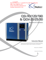
Fig. 3-1
3 Phase Magnetic Motor Starter With Automatic Start / Stop Control
Wiring Schematic WP1744A (Rev. D)
Magnetic Starter
Contactor
Overload
Relay
Connect incoming power lines
at screw terminals L1, L2 & L3.
CAUTION !
Verify all wires are secure
and fasteners are torqued
before connecting power to
the unit.
All wires are red unless otherwise specied.
Dashed lines represent wires supplied by others.
At Installation, the customer is to provide:
Disconnect and branch circuit overcurrent protection and grounding
between the power supply and the electrical control enclosure in accor-
dance with the National Electrical Code (NEC), the Canadian Electrical
Code (CEC) and / or any local codes having precedence.

QP Series Quincy Compressor
2022201802, July 2014 11 3501 Wismann Lane, Quincy Ill. - 62305-3116
Fig. 3-2
Single Phase Magnetic Motor Starter With Automatic Start / Stop Control
Wiring Schematic WP1744B (Rev. D)
Magnetic Starter
Contactor
Overload
Relay
Connect incoming power lines
at screw terminals L1 & L2.
CAUTION !
Verify all wires are secure
and fasteners are torqued
before connecting power to
the unit.
All wires are red unless otherwise specied.
Dashed lines represent wires supplied by others.
At Installation, the customer is to provide:
Disconnect and branch circuit overcurrent protection and grounding
between the power supply and the electrical control enclosure in accor-
dance with the National Electrical Code (NEC), the Canadian Electrical
Code (CEC) and / or any local codes having precedence.

QP Series Quincy Compressor
2022201802, July 2014 12 3501 Wismann Lane, Quincy Ill. - 62305-3116
Fig. 3-3
Single Phase Combination Pressure Switch / Overload Relay
Wired to Motor
Connection Diagram
Connect incoming power lines
at screw terminals L1 & L2.
Pressure Switch
To Remove the Cover:
1. Turn the switch handle to “OFF” position.
2. Remove small screws on side of the cover.
3. Pull the cover away from the pressure switch.
To Re-install the Cover:
1. Make sure the switch handle is in the “OFF”
position (as shown).
2. Carefully slide the cover over the pressure
switch.
DO NOT FORCE!
3. Re-install the small cover screws and tighten.
CAUTION !
Verify all wires are secure
and fasteners are torqued
before connecting power to
the unit.
At Installation, the customer is to provide:
Branch circuit overcurrent protection and grounding between the power supply
and the pressure switch in accordance with the National Electrical Code (NEC),
the Canadian Electrical Code (CEC) and / or any local codes having precedence.

QP Series Quincy Compressor
2022201802, July 2014 13 3501 Wismann Lane, Quincy Ill. - 62305-3116
Fig. 3-4
Start / Stop Control
Piping Schematic WP1781B

QP Series Quincy Compressor
2022201802, July 2014 14 3501 Wismann Lane, Quincy Ill. - 62305-3116
Fig. 3-5
Continuous Run - Load / Unload Control
Piping Schematic WP1781C

QP Series Quincy Compressor
2022201802, July 2014 15 3501 Wismann Lane, Quincy Ill. - 62305-3116
Fig. 3-6
Dual Control with Pilot Valve Unloading
Piping Schematic WP1781A

QP Series Quincy Compressor
2022201802, July 2014 16 3501 Wismann Lane, Quincy Ill. - 62305-3116
Fig. 3-7
Dual Control with Solenoid Valve Unloading
Piping Schematic WP1781

QP Series Quincy Compressor
2022201802, July 2014 17 3501 Wismann Lane, Quincy Ill. - 62305-3116
Overload relays are designed to protect the motor from damage
due to motor overload. If the overload relay trips persistently, DO
NOT CONTINUE TO PUSH THE RESET BUTTON! Contact your lo-
cal Quincy distributor for assistance.
Mounting
The compressor unit must be removed from the shipping skid prior
to operation.
Proper mounting of QP series compressor units is
crucial to the safe operation and longevity of the
equipment. The installation requires a at and level
concrete oor or pad (for mobile units see Mount-
ing Mobile Units). Satisfactory results can usually
be obtained by mounting horizontal tank units on
vibration isolating pads available from your local
Quincy distributor. All vertical tank units must be
anchored! Refer to Fig. 3-8, Isolator Installation
for Unanchored or Anchored Receivers. Quincy
recommends that all vertical tank units be mounted
as indicated without isolators.
State or local codes may mandate that the compres-
sor be bolted to the oor. In this case the unit must be
leveled and bolted making absolutely certain the feet are not stressed in any
manner. Leave the locknut loose! Uneven feet drawn tightly to the concrete
pad will cause severe vibrations resulting in cracked welds or fatigue failure.
The customer is responsible for pro viding a suitable foundation & isolator
mounting where necessary.
Mounting Mobile Units
Gas engine driven compressors mounted to truck beds should be fas tened
in such a way so as not to create any stress to the air receiver tank. Truck
beds, characteristically, have a tendency to ex and could cause damage to
the receiver tank if the tank is fastened directly to the truck bed. It is the
user’s responsibility to provide an adequate means of fas tening the unit in
these applica tions.
Do not operate this compressor more than 15° off level or move it
while it is operating.
System components
Efficiency and safety are the primary concerns when selecting compo nents
for compressed air systems. Products of inferior quality can not only hinder
performance of the unit, but could cause system failures that result in bodily
harm or even death. Select only top quality compo nents for your system. Call
your local Quincy distributor for quality parts and professional advice.
Drive Pulleys / Sheaves
Various pulley and sheave combinations are available to obtain the de sired air
pressure and delivery rate of your compressor. Consideration must be given
HORIZONTAL TANK UNITS
ANCHORED
VERTICAL TANK UNITS
ANCHORED
HORIZONTAL TANK UNITS
UNANCHORED
1/2” locknut
1/2” at washer
tank foot
isolator backing plate
1/2” x 2” bolt
isolator
1/2” locknut
1/2” at washer
tank foot
isolator backing plate
isolator
1/2” oor stud
(provided by customer)
1/2” oor stud
(provided by customer)
tank foot
1/2” locknut
1/2” at washer
Fig. 3-18 Isolator Installation for
Unanchored or Anchored Receivers
CAUTION !
CAUTION !
WARNING !

QP Series Quincy Compressor
2022201802, July 2014 18 3501 Wismann Lane, Quincy Ill. - 62305-3116
to these combinations to ensure that the motor is not over loaded by operating
above or below the designed speed range.
Whatever combination is employed, the drive pulleys & com pressor sheaves
must be properly aligned and drive belt tension set to specica tions (refer to
SECTION 5, Pulley / Sheave Alignment & Belt Tension). Improper pul-
ley/sheave alignment and belt ten sion can cause motor overloading, excessive
vibration, and prema ture belt and/or bearing failure.
Excessive compressor RPM’s (speed) could cause a pulley or sheave
to shatter. In an instant, the pulley or sheave could separate into
fragments capable of penetrating the belt guard and causing bodily
harm or death. Do not operate the compressor above the recom-
mended RPM (refer to SECTION 2, Specifications).
Guards
All mechanical action or motion is hazardous in varying degrees and needs
to be guarded. Guards should be designed to achieve the required degree of
protection and still allow full air ow from the compressor sheave across the
unit. Guards shall be in compliance with OSHA safety and health standards
29 CFR 1910.219 in OSHA manual 2206 and any state or local codes.
Guards must be fastened in place before starting the compressor
and never removed before cutting off and locking out the main
power supply.
Check Valves
Check valves are designed to prevent back-ow of air pressure in the com-
pressed air system (air ows freely in one direction only). The check valve must
be properly sized for air ow and tempera ture. Do not rely upon a check
valve to isolate a compressor from a pressurized tank or compressed
air delivery system during main tenance procedures!
Manual Shutoff Valves
Manual shutoff valves block the ow of air pressure in either direction. This
type of valve can be used to isolate a compressor from a pressurized system,
provided the system is equipped with a pressure relief valve ca pable of being
manually released. The pressure relief valve must be installed between the
manual shutoff valve and the compressor (refer to Fig. 3-9, Typical Drop
Leg & Component Location).
Pressure Relief Valves
Pressure relief valves aid in preventing system failures by relieving system
pressure when compressed air reaches a determined level. They are available
in various pressure settings to accommodate a range of applications. Pressure
relief valves are preset by the manufacturer and under no circumstances should
the setting be changed by anyone other than the manufacturer.
Pressure relief valves are designed to protect compressed air
systems in accordance with ASME B19 safety standards. Failure to
provide properly sized pressure relief valves may cause property
damage, severe personal injury or even death.
WARNING !
WARNING !
DANGER !
/