Page is loading ...

INTRODUCTION 4
PREPARATION 11
RECORDING
OPERATION 23
PLAYBACK
OPERATION 39
NOTICE 44
Instruction
Manual
VIRTUAL REAL-TIME &
TIME LAPSE VCR
KV-7168A
POWER
TAPE REMAIN
TIME LAPSE VCR
4Head 168Hour
DISPLAY
PLAY
STOP REV FWD
TIME MODE
SET
SHIFT
TRACKING
LOCATION SELECT
COUNTER
ALARM RESETMEMORY
+–
PAUSE/STILL

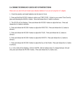
Only cassettes marked can be used with this VCR. This VCR is not compatible with ordinary VCRs.
PLEASE READ
The lightning flash with arrowhead symbol, within an equilateral triangle,
is intended to alert the user to the presence of uninsulated “dangerous
voltage” within the product’s enclosure that may be of sufficient magni-
tude to constitute a risk of electric shock to persons.
The exclamation point within an equilateral triangle is intended to alert
the user to the presence of important operating and maintenance
(servicing) instructions in the literature accompanying the appliance.
WARNING: TO REDUCE THE RISK OF ELEC-
TRIC SHOCK, DO NOT REMOVE COVER (OR
BACK). NO USERSERVICEABLE PARTS IN-
SIDE. REFER SERVICING TO QUALIFIED
SERVICE PERSONNEL.
Save Original Packing Materials
The original shipping carton and packing materials will come in handy if you ever have to ship your VCR. For maximum protection,
repack the set as it was originally packed at the factory.
WARNING
WARNING: TO REDUCE THE RISK OF FIRE OR ELECTRIC SHOCK, DO NOT EXPOSE THIS APPLIANCE TO
RAIN OR MOISTURE. DANGEROUS HIGH VOLTAGES ARE PRESENT INSIDE THE ENCLOSURE.
DO NOT OPEN THE CABINET. REFER SERVICING TO QUALIFIED PERSONNEL ONLY.
CAUTION: TO PREVENT ELECTRIC SHOCK, MATCH WIDE BLADE OF PLUG TO WIDE SLOT, FULLY INSERT.
ATTENTION: POUR ÉVITER LES CHOCS ÉLECTRIQUES, INTRODUIRE LA LAME LA PLUS LARGE DE LA FICHE
DANS LA BORNE CORRESPONDANTE DE LA PRISE ET POUSSER JUSQU’AU FOND.
USER-INSTALLER CAUTION : YOUR AUTHORITY TO OPERATE THIS FCC VERIFIED EQUIPMENT CLOUD BE
VOIDED IF YOU MAKE CHANGES OR MODIFICATIONS NOT EXPRESSLY APPROVED BY THIS PARTY RESPON-
SIBLE FOR COMPLIANCE TO PART 15 OF THE FCC RULES.
NOTE: This equipment has been tested and found to comply with the limits for Class A digital device,
pursuant to Part 15 of the FCC Rules. These limits are designed reasonable protection against
harmful interference when the equipment is operated in a commercial environment. This equipment
generates, uses, and can radiate radio frequency energy and, if not installed and used in
accordance with the instruction manual, may cause harmful interference to radio communications.
Operation of this equipment in a residential area is likely to cause harmful interference in which
case the user will be required to correct the interference at his own expense.
In the spaces provided below, record the Model and Serial No. located at the rear of your video cassette recorder.
Model No. Serial No.
Retain this information for future reference.
IMPORTANT PRECAUTIONS
INTRODUCTION
RISK OF ELECTRIC SHOCK
DO NOT OPEN.
Copyright: To record video tapes and other material only in the event that third party copyrights and other rights are not
violated.
Dew Condensation
Never operate this VCR immediately after moving it from a cold location to a warm location. When the VCR is exposed to such a change
in temperature, dew condensation may occur on the cylinder inside it, one of its most crucial internal parts. The VCR is equipped with
an automatic dew condensation prevention circuit designed to cope with this problem. It takes about TWO HOURS for this circuit to
work with the power cord plugged in. Please do not use the VCR during this time.
Daily Maintenance
Before beginning the day’s operation, rewind the cassette tape recorded on the previous day a few counts and play it back to check
for proper recording.
In order to maintain recorded content and machine itself, and to prevent troubles, the use of high quality video cassette tape is
recommended. Tapes which have been used for long period, used repeatedly, or kept in an unpreferable condition such as high
temperature, high humidity, or strong magnetic field may cause deterioration of picture quality and some troubles. We therefore
recommend use of T-120 video tapes.
Cassette Tape
1

RECORDING
OPERATION
PREPARATION
INTRODUCTION
PLAYBACK
OPERATION
NOTICE
2
CAUTION: PLEASE READ AND OBSERVE ALL WARNINGS AND INSTRUCTIONS GIVEN IN THIS OWNER’S MANUAL AND
THOSE MARKED ON THE UNIT. RETAIN THIS BOOKLET FOR FUTURE REFERENCE.
This set has been designed and manufactured to assure personal safety. Improper use can result in electric shock or fire hazard.
The safeguards incorporated in this unit will protect you if you observe the following procedures for installation, use and servicing.
This unit is fully transistorized and does not contain any parts that can be repaired by the user.
DO NOT REMOVE THE CABINET COVER, OR YOU MAY BE EXPOSED TO DANGEROUS VOLTAGE. REFER SERVICING TO
QUALIFIED SERVICE PERSONNEL ONLY.
5. Heat
The product should be situated
away from heat sources such as
radiators, heat registers, stoves,
or other products (including am-
plifiers) that produce heat.
6. Water and Moisture
Do not use this product near wa-
ter - for example, near a bath tub,
wash bowl, kitchen sink, or laun-
dry tub; in a wet basement; or
near a swimming pool and the
like.
7. Cleaning
Unplug this product from the wall
outlet before cleaning. Do not
use liquid cleaners or aerosol
cleaners. Use a damp cloth for
cleaning.
8. Power-Cord Protection
Power-supply cords should be
routed so that they are not likely
to be walked on or pinched by
items placed upon or against
them, paying particular attention
to cords at plugs, convenience
receptacles, and the point where they exit from the product.
9. Overloading
Do not overload wall outlets; ex-
tension cords, or integral
convenience receptacles as this
can result in a risk of fire or elec-
tric shock.
IMPORTANT SAFETY INSTRUCTIONS
1. Read owner’s manual
After unpacking this product, read
the owner’s manual carefully, and
follow all the operating and other
instructions.
2. Power Sources
This product should be operated
only from the type of power source
indicated on the marking label. If
you are not sure of the type of
power supply to your home, con-
sult your product dealer or local
power company. For products in-
tended to operate from battery power, or other sources, refer
to the operating instructions.
3. Grounding or Polarization
This product may be equipped
with a polarized alternating cur-
rent line plug (a plug having one
blade wider than the other). This
plug will fit into the power outlet
only one way. This is a safety
feature. If you are unable to insert
the plug fully into the outlet, try reversing the plug. If the plug
should still fail to fit, contact your electrician to replace your
obsolete outlet. Do not defeat the safety purpose of the
polarized plug.
4. Ventilation
Slots and openings in the cabinet
are provided for ventilation and to
ensure reliable operation of the
product and to protect it from over-
heating, and these openings must
not be blocked or covered. The
openings should never be blocked
by placing the product on a bed,
sofa, rug or other similar surface. This product should not be
placed in a built-in installation such as a bookcase or rack
unless proper ventilation is provided or the manufacturer’s
instructions have been adhered to.

NOTICE
PREPARATION
INTRODUCTION
RECORDING
OPERATION
PLAYBACK
OPERATION
3
10.Outdoor Antenna Grounding
If an outside antenna or cable system is connected to the
product, be sure the antenna or cable system is grounded so
as to provide some protection against voltage surges and
built-up static charges. Article 810 of the National Electrical
Code, ANSI/NFPA 70, provides information with regard to
proper grounding of the mast and supporting structure,
grounding of the lead-in wire to an antenna discharge unit,
size of grounding conductors, location of antenna-discharge
unit, connection to grounding electrodes, and requirements
for the grounding electrode.
11.Power Lines
An outside antenna system should not be located in the
vicinity of overhead power lines or other electric light or
power circuits, or where it can fall into such power lines or
circuits. When installing an outside antenna system, ex-
treme care should be taken to keep from touching such
power lines or circuits as contact with them might be fatal.
12.Lightning
For added protection for this prod-
uct during storm, or when it is left
unattended and unused for long
periods of time, unplug it from the
wall outlet and disconnect the
antenna or cable system. This
will prevent damage to the prod-
uct due to lightning and power-line surges.
13.Object and Liquid Entry
Never push objects of any kind
into this product through open-
ings as they may touch dangerous
voltage points or short-out parts
that could result in a fire or electric
shock. Never spill liquid of any
kind on the product.
14.Attachments
Do not use attachments not recommended by the product
manufacturer as they may cause hazards.

RECORDING
OPERATION
PREPARATION
INTRODUCTION
PLAYBACK
OPERATION
NOTICE
INTRODUCTION
FEATURES
Restart record function.
This function enables the VCR to automatically restart the record-
ing process in the event of a power failure. After power is restored,
the VCR will restart the recording process. (See page 24.)
Shuttle function.
With the shuttle dial, a wide variety of playback functions are
available. They include picture search, slow playback, field
advance playback, reverse field advance playback, and still
playback (See pages 40 - 41.)
Clean slow and still.
A clean crisp image is crucial and is the main purpose for the
existence of a surveillance recorder. This VCR offers a clean and
noiseless playback, that is essential for surveillance applications.
Time date search function.
With time date search, it is possible to search for a picture recorded
on a certain time and date. (See page 42.)
Head cleaning function.
Head cleaning is automatically performed at the end of timer
recording and at tape end in order to prevent head jamming. There
is also head cleaning once every two hours when operating in time
modes of 24 hours or more.
Automatic head clog detection.
When recording in time mode 120 and 168 hours or in the One-
shot mode, video head clog detection is autimatically carried out
once for every two hours. When the video head clog is found, head
cleaning is carried out for approximately 10 times. When cleaning
is still not possible, "E-6" is displayed.
Record check function.
By pressing the record check button during recording, the VCR
automatically replays the last few seconds of the recording. (See
page 5, note ).
Wired remote control function (Option)
The wired remote control allows the following VCR functions.
• Fast Forward • Forward picture search
• Rewind • Reverse picture search
• Pause • Still
• Field advance (forward, reverse)
• Play • Stop
• Play back time
Various time modes.
With a T-120 tape, it is possible to record over periods ranging from
2 to 168 hours.
A2, A6, A12, A18, A24, 24, 48, 72, 120 and 168 modes are
explained in more detail. (See page 21.)
Virtual real-time recording is possible.
It is possible to virtual real-time record in A18 mode.
(See page 21.)
Internal time-date generator.
This VCR includes an internal time-date generator, necessary for
documentation purposes. (See page 15.)
On-screen programming.
Menu driven programming simplifies set-up of various functions
including but not limited to the following:
time & date search, timer setting, and alarm recording.
Timer recording function.
With timer recording, it is possible to set two programs for each day
of the week as well as one daily program. Up to 15 programs total
are available for timer recording.
(See pages 25 - 28.)
Tape remaining function.
With this feature, it is possible to check the time remaining until the
end of tape during the recording process as well as playback
process. (See page 6, note .)
Alarm record function.
With a dry contact closure upon the alarm input terminal, it is
possible to set the VCR into alarm mode. When recording in the
alarm mode, the VCR automatically enters into a mode which
usually is a faster recording mode. This is done so that more
information can be recorded.
One-shot recording possible.
External trigger input makes it possible to record from 1 to 32 fields
and Manual mode.
Alarm memory search function.
This VCR provides an alarm memory function for finding the alarm
event during playback. (See page 43.)
Repeat record function.
Repeat record function enables the VCR to automatically rewind
the tape when it reaches the end and restarts the recording
process. (See page 36.)
4
RESTART RECORDING ..........................................................................24
TIMER RECORDING................................................................................25
ALARM RECORDING ..............................................................................29
ONE SHOT RECORDING ........................................................................31
SETTING OF OPERATION AFTER TAPE END DETECTION ................ 34
AUTO REWIND AFTER RECORDING ..............................................35
REPEAT RECORDING ......................................................................36
RECORDING WITH THE SEQUENTIAL SWITCHER ............................. 37
PLAYBACK OPERATION ........................................................................39 ~ 43
PLAYBACK............................................................................................... 39
PLAYBACK IN VARIOUS MODE ............................................................. 41
TIME DATE SEARCH...............................................................................42
ALARM SEARCH .....................................................................................43
NOTICE ..................................................................................................44 ~ 50
SIGNAL LEVELS OF INPUT/OUTPUT .................................................... 44
DAILY AND PERIODIC INSPECTION ..................................................... 45
CAUTIONS DURING USE........................................................................47
BEFORE CALLING SERVICE PERSONNEL .......................................... 48
SPECIFICATIONS.................................................................................... 50
TABLE OF CONTENTS
PLEASE READ ..................................................................................................1
IMPORTANT PRECAUTIONS ...........................................................................1
IMPORTANT SAFETY INSTRUCTIONS .....................................................2 ~ 3
INTRODUCTION ....................................................................................... 4 ~ 10
FEATURES.................................................................................................4
TABLE OF CONTENTS..............................................................................4
INSTRUCTIONS IN BRIEF......................................................................... 5
VCR DISPLAY ............................................................................................9
WIRED REMOTE CONTROL (Option) ..................................................... 10
PREPARATION .......................................................................................11 ~ 22
CONNECTIONS ....................................................................................... 11
CONTENTS OF SCREEN DISPLAY........................................................ 13
SETTING THE CLOCK.............................................................................15
ON-SCREEN FUNCTIONS ...................................................................... 16
DISPLAY SCREEN ..................................................................................17
COUNTER DISPLAY................................................................................ 19
SETTING THE RECORDING/PLAYBACK TIME .....................................21
LOADING AND UNLOADING A VIDEO CASSETTE ...............................22
RECORDING OPERATION .....................................................................23 ~ 38
RECORDING ............................................................................................ 23

NOTICE
PREPARATION
INTRODUCTION
RECORDING
OPERATION
PLAYBACK
OPERATION
INSTRUCTIONS IN BRIEF
Front Panel
5
+

RECORDING
OPERATION
PREPARATION
INTRODUCTION
PLAYBACK
OPERATION
NOTICE
6
TAPE REMAIN button
The approximate time remaining on the tape is displayed
on the counter (in a 2 hour scale using a T-120 tape) while
this button is being pressed.
CASSETTE COMPARTMENT
Insert a cassette into this compartment to load the tape.
DISPLAY button
Press to display the MENU screen and change the
settings.
SHIFT / button
Press to select a desired menu on the screen.
TIME MODE / SET + – buttons
• Press either of the buttons to set the recording time
mode and playback time mode.
• Press either the + or the – button to set the mode and
the numerical value for each menu on the screen.
LOCATION SELECT button /
Press to change the position of superimposed characters
on the screen.
TRACKING buttons ( / )
Adjust to eliminate noise from playback picture.
PLAY button
Press to start the playback mode.
STOP button
Press to stop tape running.
PAUSE/STILL button
• Press during recording to pause recording.
• Press during playback for a still picture.
SHUTTLE dial
Turn this dial clockwise and hold:
• To fast forward the tape during the stop mode.
• To operate the forward picture search during the play-
back.
• To operate the forward slow play during the still mode.
Turn this dial counter clockwise and hold:
• To rewind the tape during the stop mode.
• To operate the reverse picture search during the play-
back.
• To operate the reverse slow play during the still mode.

NOTICE
PREPARATION
INTRODUCTION
RECORDING
OPERATION
PLAYBACK
OPERATION
VIDEO OUT connector (BNC)
Output connector for video signal. Connect with a monitor
TV.
AUDIO IN jack (RCA type)
Input jack for audio signal. Connect with an external audio
source.
AUDIO OUT jack (RCA type)
Output jack for audio signal. Connect with an external
audio equipment.
ONE SHOT IN terminal
Input terminal to start one shot recording.
The VCR goes into one shot recording mode when this
terminal is connected to the ground terminal while in the
L01, L02 or L03 record mode.
Notes:
• ALL CLEAR button
Do not use this function (ALL CLEAR) frequently.
Press this button only when an abnormality (ex. VCR
display does not turn ON.) occurs.
When this button is pressed, the power turns OFF and
each data stored (ex. clock, timer program, etc.) is cleared
and returns to the initial setting status. It will be necessary
to re-program the VCR after turning the unit on again.
• OPTION BOX cover
This VCR provides an optional port for connecting an
optional module to the rear of the unit.
If you would like additional information regarding the
available options for this VCR please consult your dealer.
The installation of the optional module should be per-
formed only by qualified technical personnel.
Rear Panel
7
TAPE END OUT terminal
Signal output terminal to annunciate to other devices that
the tape has run out on the VCR.
REC TRIGGER OUT terminal
Signal output terminal to control the switching interval of
the video cameras when connected to a sequential
switcher or multiplexer.
ALARM OUT terminal
Output terminal to transmit an alarm signal to peripheral
equipment.
ALARM RESET terminal
Input terminal to reset alarm recording.
Alarm recording is reset when this terminal is connected to
the ground terminal during recording.
ALARM IN terminal
Input terminal to start alarm recording.
The VCR goes into alarm recording mode when this
terminal is connected to the ground terminal while in the
record mode, record pause mode, or stop mode.
ALL CLEAR button
Pressing this button will clear the entire time-date, and
timer program memory. The power will be turned off at the
same time. Pressing the POWER button will restore
power.
REMOTE IN jack
Input jack for optional wired remote control.
MIC IN jack
Input jack for audio signals from a microphone. The RCA
jack input (audio input) is automatically switched off when
this jack is utilized.
VIDEO IN connector (BNC)
Input connector for video signal. Connect with an external
video source such as a video camera, etc.
ALL CLEAR
REMOTE IN
MIC IN
IN
GND
RESET
OUT
GND
OUT
GND
TAPE END
ALARM
REC
TRIGG.

RECORDING
OPERATION
PREPARATION
INTRODUCTION
PLAYBACK
OPERATION
NOTICE
A Word on the Exclusive 3N-100AAS
Battery Pack
The nickel-cadmium battery pack (3N-100AAS) is used for
power source of the built-in clock and memory circuit.
Charging the Battery Pack
1. Turn on the power of the VCR.
2. The battery pack in the VCR is charged.
Battery Installation
Removal:
1. Remove the battery cover.
2. Disconnect the connector in the VCR.
Specification of Battery
Temperature
For charging : 0°C to 80°C
For operating : –20°C to 80°C
For storing : –30°C to 80°C
Charging time : more than 48 hours
Notes:
Use only for this VCR.
Do not dispose of the batteries into fire.
Do not short circuit the terminals.
Do not modify or disassemble.
Avoid dropping, unnecessary shocks.
8
Connector
RED wire
Battery pack
Installation:
1. Install the battery pack placing the red wire upside, and
connect the connector on the battery pack to this VCR.
Make sure the polarities (+) and (–) are correct.
2. Close the battery cover.
Note:
If the Battery Pack is removed, the memory data will be
erased. In such a case, perform the setting from the first step.

NOTICE
PREPARATION
INTRODUCTION
RECORDING
OPERATION
PLAYBACK
OPERATION
PLAY REC
ALARM
COUNT.
M
ALARM
M
PW.FAIL
DEW
TIMER
H
SP
EP
VCR DISPLAY
10
Cassette indicator
Lights when a tape is inserted.
Counter memory indicator
Lights when the counter memory is selected.
Alarm Memory indicator
Lights when the alarm memory is selected.
Alarm indicator
Lights during alarm recording and blinks after an alarm
recording cycle is completed.
PW.FAIL (Power Failure) indicator
Blinks when a power failure occurs.
TAPE operation indicator
Displays as shown below, depending on operational
modes.
Playback
Other than playback
Playback
Still
Slow
Reverse
Picture Search
Forward
Picture Search
Reverse
Playback
Field Advance
PLAY
PLAY
PLAY
PLAY
PLAY
PLAY
PLAY
Counter/Alarm Counter/Remaining Tape/Error Mes-
sage indicator
• Press the ALARM button to display the alarm counter.
• Press the ALARM button again to return to display the
counter.
• Press the TAPE REMAIN button to display the remaining
tape time.
• When an abnormality occurs during operation, the error
code is displayed.
E-1: Abnormality on reel rotation during tape running.
E-3: Abnormality on cylinder rotation during recording
and playback.
E-4: Abnormality on tape loading mechanism.
E-5: Video tape is cut.
E-6: Head clog.
E-8: Dew condensation.
Dew indicator
Blinks when the dew condensation has developed inside
the VCR.
Timer indicator
Lights when the timer recording button is pressed and the
VCR has been set in timer record mode.
Record/Playback Time indicator
Displays record/playback time mode.
9
PLAY
Reverse
Field Advance
Record
Pause
Time-lapse
Fast Forward
Rewind
REC
REC
REC
10

RECORDING
OPERATION
PREPARATION
INTRODUCTION
PLAYBACK
OPERATION
NOTICE
PLAY
(–) PLAY TIME (+)
STOP
REW FF
STILL
PAUSE/
PICTURE
SEARCH
WIRED REMOTE CONTROL (Option)
10
PAUSE/STILL button
• Press during recording to pause the recording.
• Press during playback to play back a still picture.
REW button
• Press to rewind the tape.
• Press during playback for reverse picture search.
To release the reverse picture search mode, press the
PLAY button.
• Press the REW button while pressing the PLAY button,
the time mode can be selected.
• Each time pressing the REW button during still playback
mode, the Reverse Field Advance playback (one field)
will be carried out.
STOP button
Press to stop tape running.
PLAY button
Press to start play back.
FF button
• Press to fast forward mode.
• Press during playback for forward picture search mode.
To release the forward picture search mode, press the
PLAY button.
• Press the FF button while pressing the PLAY button, the
Time mode can be selected.
• Each time pressing the FF button during still playback
mode, the Field Advance playback (one field) will be
carried out.
Note:
If your wish to obtain the wired remote control, please consult
your dealer.

NOTICE
PREPARATION
INTRODUCTION
RECORDING
OPERATION
PLAYBACK
OPERATION
CONNECTIONS
Connection with a Video Camera
PREPARATION
11
ALL CLEAR
REMOTE IN
MIC IN
IN
GND
RESET
OUT
GND
OUT
GND
TAPE END
ALARM
REC
TRIGG.
IN
OUT
VIDEO
IN
OUT
AUDIO
SEE MANUALSEE MANUAL
Monitor TV
To AC OUTLET
(120V)
To AC OUTLET
(120V)
QUAD
ONLY
SWITCHED
OFF
LOOP
THROUGH
IN
ON
75Ω
FRONT
PANEL
DISABLE
ENABLE
REMOTE
FUSE
1A
125V
AC IN
1234
VIDEO INPUT
VIDEO OUTPUT
EXT. REF INPUT
To QUAD. OUT
To VIDEO IN To VIDEO OUT
To VIDEO IN
To AC OUTLET
(120V)
Quadrant picture unit
IN
ONE
SHOT
ALL CLEAR
REMOTE IN
MIC IN
IN
GND
RESET
OUT
GND
OUT
GND
TAPE END
ALARM
REC
TRIGG.
IN
OUT
VIDEO
IN
OUT
AUDIO
SEE MANUALSEE MANUAL
To VIDEO OUT (BNC connector)
To VIDEO IN
(BNC connector)
RG/59u coaxial
cable.
To VIDEO OUT
(BNC connector)
To VIDEO IN
(BNC connector)
camera
Monitor TV
To AC OUTLET
(120V)
To AC OUTLET
(120V)
IN
ONE
SHOT

RECORDING
OPERATION
PREPARATION
INTRODUCTION
PLAYBACK
OPERATION
NOTICE
VIDEO IN VIDEO OUT
12345
CAMERA
ALARM IN
REMOTE
678
12345678
ALARM
OUT
MONITOR
VCR
REC
VCR
PLAY
Monitor TV.
AC120V
To AC outlet
To ALARM IN
To VCR playback
Frame Sequential Switcher
To VCR REC
To ALARM
OUTPUT
To VIDEO OUT
To GND
To REC TRIGGER INPUT
To REC TRIGG. OUT
To
VIDEO IN
ALL CLEAR
REMOTE IN
MIC IN
IN
GND
RESET
OUT
GND
OUT
GND
TAPE END
ALARM
REC
TRIGG.
IN
OUT
VIDEO
IN
OUT
AUDIO
SEE MANUAL
SEE MANUAL
IN
ONE
SHOT
Typical Connection with the Sequential Switcher
When connected with a sequential switcher, set the alarm recording mode to MANUAL by menu screen.
For further details, consult the instruction manuals of the connected devices.
12
When using the VCR connected to a frame sequential switcher, pay
attention to the following matters.
When playing back in the A12, A18 or A24-hour mode, mixing of
pictures from other channels may occur. If this occurs, play back in a
mode other than the A12, A18 or A24-hour mode.
If the following phenomena occur during playback in a time mode of
24 hours or longer, adjust by using the TRACKING button.
1. Mixing of signals from another channel.
Go to slow playback and press the TRACKING button to adjust
until the picture appears from the channel you want to view.
2. Picture waves up and down.
Press the TRACKING button during still picture playback and
adjust the picture until the picture stops waving up and down.

NOTICE
PREPARATION
INTRODUCTION
RECORDING
OPERATION
PLAYBACK
OPERATION
The normal MENU screen provides six menus after the initial screen for clock setting. Each MENU screen is shown below.
Press the DISPLAY button for a MENU screen. The menu is selected by pressing the SHIFT button. Then press the SET button to
proceed to the next screen. Use the SHIFT button and the SET button for settings and adjustments in the same manner. To return
to the initial screen press the DISPLAY button.
CONTENTS OF SCREEN DISPLAY
Monitor Screen (initial screen)
MENU Screen (initial screen)
CLOCK SET Screen
Comment
Setting of clock.
Unless the date-time is
adjusted, the “PROGRAM”
and “ALARM RECALL” will
not appear on the MENU
screen.
Monitor Screen (normal screen)
MENU Screen (normal screen)
DISPLAY Screen
SETUP Screen
CLOCK ADJUST Screen
Correction of date-time.
Setting of alarm recording
mode (recording time,
recording mode)
Setting of One-Shot
recording mode (number of
recording fields, recording
intervals).
Setting of recording for
restoration of power following
a power failure.
Setting of operation after
detection of tape end (tape
end detection mode for tape
end detection during
recording and when an alarm
recording is made).
Setting of display screen
(date, day of week, time,
recording time, VCR number,
alarm).
Setting of time display (24H,
12H).
13
0:00:00 A 2
1/ 1/95 SUN
17:30:02 A 2
8/28/96 WED
M E N U
CLOCK SET
SETUPSETUP
DISPLAY MODE
END=[DISPLAY]
TIME DATE SEARCH
M E N U
CLOCK ADJUST
SETUPSETUP
DISPLAY MODE
END=[DISPLAY]
PROGRAM
ALARM RECALL
TIME DATE SEARCH
M E N U
CLOCK ADJUST
SETUP
DISPLAY MODE
END=[DISPLAY]
PROGRAM
ALARM RECALL
TIME DATE SEARCH
M E N U
CLOCK ADJUST
SETUPSETUP
DISPLAY MODE
END=[DISPLAY]
PROGRAM
ALARM RECALL
TIME DATE SEARCH
CLOCK SET
MENU=[DISPLAY]
(MONTH) (DAY) (YEAR)
1 / 1 / '95
SUN
0:00(TIME)
(DAYLIGHT
SAVING TIME) OUT
CLOCK ADJUST
MENU=[DISPLAY]
(MONTH) (DAY) (YEAR)
8 / 28 / '96
WED
17:30(TIME)
(DAYLIGHT
SAVING TIME) IN
RESTART REC OFF
TAPE END MODE STOP
ALARM STOP
S E T U P
1SHOT REC FIELD 1F
MENU=[DISPLAY]
INTERVAL 0.2S
ALARM REC TIME 15S
SPEED A 2H
(TIME) ON
(SPEED) ON
(VCR) OFF
(ALARM) ON
(12H/24H) 24H
(CHAR.LINES) 6
DISPLAY
(DATE) ON
MENU=[DISPLAY]
(DAY OF THE WEEK) ON

RECORDING
OPERATION
PREPARATION
INTRODUCTION
PLAYBACK
OPERATION
NOTICE
PROGRAM Screen
Setting of timer
recording.
ALARM RECALL Screen
TIME DATE SEARCH Screen
Alarm recall
display
Set the day and
time to be
searched and
searching
direction.
14
M E N U
CLOCK ADJUST
SETUPSETUP
DISPLAY MODE
END=[DISPLAY]
PROGRAM
ALARM RECALL
TIME DATE SEARCH
TH2 ON --:-- --:-- 120H
WE2 ON --:-- --:-- 120H
WE1 ON --:-- --:-- 120H
TU2 ON --:-- --:-- 120H
TU1 ON --:-- --:-- 120H
TH1 ON --:-- --:-- 120H
PROGRAM
MO1 ON --:-- --:-- 120H
MENU=[DISPLAY]
MO2 ON --:-- --:-- 120H
➜
➜
➜
➜
➜
➜
➜
➜
M E N U
CLOCK ADJUST
SETUPSETUP
DISPLAY MODE
END=[DISPLAY]
PROGRAM
ALARM RECALL
TIME DATE SEARCH
1ST --/--/----- --:--:--
AL6 --/--/----- --:--:--
AL5 --/--/----- --:--:--
AL4 --/--/----- --:--:--
AL3 --/--/----- --:--:--
AL7 --/--/----- --:--:--
ALARM RECALL
AL1 --/--/----- --:--:--
MENU=[DISPLAY]
AL2 --/--/----- --:--:--
M E N U
CLOCK ADJUST
SETUPSETUP
DISPLAY MODE
END=[DISPLAY]
PROGRAM
ALARM RECALL
TIME DATE SEARCH
REVERSE
SEARCH FORWARD
MINUTE 00
TIME DATE SEARCH
DAY 1
MENU=[DISPLAY]
HOUR 0

NOTICE
PREPARATION
INTRODUCTION
RECORDING
OPERATION
PLAYBACK
OPERATION
DISPLAY
TIME MODE
SET
SHIFT
TRACKING
LOCATION SELECT
+–
DISPLAY
TIME MODE
SET
SHIFT
TRACKING
LOCATION SELECT
+–
An internal clock generates time and date for superimposing on the monitor screen. Adjust the time from the MENU screen (initial
screen). After the clock is set, the data and time modes are displayed on the monitor screen (live picture).
SETTING THE CLOCK
Operation
In case of setting to 5:30 PM, Wednesday, August 28, 1996;
1
Press the DISPLAY
button.
2
Press the + SET button.
3
Press the + SET button
and set the DAYLIGHT
SAVING TIME to IN.
4
Press the SHIFT
button to blink Month
and press the + SET
button to set to “8”.
5
Press the SHIFT
button to blink Day and
press the + SET button
to set to “28”.
7
Press the SHIFT
button to blink Time in
hours and press the +
SET button to set to “17”.
8
Press the SHIFT
button to blink Time in
minutes and press the +
SET button to set to “30”.
9
Press the DISPLAY
button to start display of
the set date and time.
10
Press the DISPLAY
button to return to the
normal screen.
6
Press the SHIFT
button to blink Year and
press the + or – SET
button to set to “96”.
DISPLAY
TIME MODE
SET
SHIFT
TRACKING
LOCATION SELECT
+–
DISPLAY
TIME MODE
SET
SHIFT
TRACKING
LOCATION SELECT
+–
DISPLAY
TIME MODE
SET
SHIFT
TRACKING
LOCATION SELECT
+–
DISPLAY
TIME MODE
SET
SHIFT
TRACKING
LOCATION SELECT
+–
DISPLAY
TIME MODE
SET
SHIFT
TRACKING
LOCATION SELECT
+–
DISPLAY
TIME MODE
SET
SHIFT
TRACKING
LOCATION SELECT
+–
DISPLAY
TIME MODE
SET
SHIFT
TRACKING
LOCATION SELECT
+–
DISPLAY
TIME MODE
SET
SHIFT
TRACKING
LOCATION SELECT
+–
15
M E N U
CLOCK SET
SETUPSETUP
DISPLAY MODE
END=[DISPLAY]
TIME DATE SEARCH
CLOCK SET
MENU=[DISPLAY]
(MONTH) (DAY) (YEAR)
1 / 1 / '95
SUN
0:00(TIME)
(DAYLIGHT
SAVING TIME) OUT
CLOCK ADJUST
MENU=[DISPLAY]
(MONTH) (DAY) (YEAR)
1 / 1 / '95
SUN
1:00(TIME)
(DAYLIGHT
SAVING TIME) IN
CLOCK SET
MENU=[DISPLAY]
(MONTH) (DAY) (YEAR)
8 / 1 / '95
TUE
1:00(TIME)
(DAYLIGHT
SAVING TIME) IN
CLOCK SET
MENU=[DISPLAY]
(MONTH) (DAY) (YEAR)
8 / 28 / '95
MON
1:00(TIME)
(DAYLIGHT
SAVING TIME) IN
CLOCK SET
MENU=[DISPLAY]
(MONTH) (DAY) (YEAR)
8 / 28 / '96
WED
1:00(TIME)
(DAYLIGHT
SAVING TIME) IN
CLOCK SET
MENU=[DISPLAY]
(MONTH) (DAY) (YEAR)
8 / 28 / '96
WED
17:00(TIME)
(DAYLIGHT
SAVING TIME) IN
CLOCK SET
MENU=[DISPLAY]
(MONTH) (DAY) (YEAR)
8 / 28 / '96
WED
17:30(TIME) 17
(DAYLIGHT
SAVING TIME) IN
M E N U
CLOCK ADJUST
SETUPSETUP
DISPLAY MODE
END=[DISPLAY]
PROGRAM
ALARM RECALL
TIME DATE SEARCH
17:30:02 A 2
8/28/96 WED

RECORDING
OPERATION
PREPARATION
INTRODUCTION
PLAYBACK
OPERATION
NOTICE
ON-SCREEN FUNCTIONS
When the power is turned ON, the time and date modes are displayed on the monitor screen (live picture). On-screen displays are
not available in the event of no video input signal.
Date-Time Display
VCR display
Monitor screen
Date : Displayed with the month-day-year.
Day of the week :Automatically set to the correct day of the week when the date is set.
Time : Set to 24-hour cycle at factory.
It is possible to modify to 12-hour (AM/PM) cycle display.
Playback/Recording Time : Playback or Recording time display
On-Screen Position
Press the LOCATION SELECT button to adjust the display to desirable position.
The display moves in the direction shown by the arrows.
However, during the date-time display screen, pay attention to the following when
setting the date and time display positions:
When the display is set to an end of the monitor screen as shown in the figure,
synchronization instability or color flickering may occur in some monitor TVs.
Press this button : To down
Press this button : To right
16
LOCATION SELECT
17:30:02 A 2
8/28/96 WED
8/28/96 WED
17:30:02 A 2
Playback/Recording time
Time3
Date1 Day of the week2
4
17:30:02 A 2
8/28/96 WED
17:30:02 A 2
8/28/96 WED
17:30:02 A 2
8/28/96 WED
17:30:02 A 2
8/28/96 WED
17:30:02 A 2

NOTICE
PREPARATION
INTRODUCTION
RECORDING
OPERATION
PLAYBACK
OPERATION
17:30:02 A 2
8/28/96 WED
17:30:02 A 2
8/28/96 WED
17:30:02 A 2
8/28/96 WED
17:30:02 A 2
8/28/96 WED
DISPLAY
TIME MODE
SET
SHIFT
TRACKING
LOCATION SELECT
+–
DISPLAY
TIME MODE
SET
SHIFT
TRACKING
LOCATION SELECT
+–
DISPLAY SCREEN
Set the MENU screen to DISPLAY screen, and select or set each item.
Before operation, set the MENU screen to DISPLAY screen (See page 13.).
Note:
Press the DISPLAY button twice to return from the display screen to the monitor screen.
Operation Display Screen Monitor Screen
Erasing the date display.
Press the
or SHIFT button to blink DATE and press
the + or – SET button to go to OFF.
Changes between OFF and ON
each time the + or – SET button
is pressed.
Erasing the day of the week display.
Press the
or SHIFT button to blink DAY OF THE
WEEK and press the + or – SET button to go to OFF.
Changes between OFF and ON
each time the SET button is
pressed.
Erasing the time display.
Press the or SHIFT button to blink TIME and press
the + or – SET button to go to OFF.
Changes between OFF and ON
each time the + or – SET button
is pressed.
Erasing the speed display.
Press the
or SHIFT button to blink SPEED and press
the + or – SET button to go to OFF.
Changes between OFF and ON
each time the + or – SET button
is pressed.
DISPLAY
TIME MODE
SET
SHIFT
TRACKING
LOCATION SELECT
+–
(TIME) ON
(SPEED) ON
(VCR) OFF
(ALARM) ON
(12H/24H) 24H
(CHAR.LINES) 6
DISPLAY
(DATE) OFF
MENU=[DISPLAY]
(DAY OF THE WEEK) ON
(TIME) ON
(SPEED) ON
(VCR) OFF
(ALARM) ON
(12H/24H) 24H
(CHAR.LINES) 6
DISPLAY
(DATE) ON
MENU=[DISPLAY]
(DAY OF THE WEEK) OFF
(TIME) OFF
(SPEED) ON
(VCR) OFF
(ALARM) ON
(12H/24H) 24H
(CHAR.LINES) 6
DISPLAY
(DATE) ON
MENU=[DISPLAY]
(DAY OF THE WEEK) ON
(TIME) ON
(SPEED) OFF
(VCR) OFF
(ALARM) ON
(12H/24H) 24H
(CHAR.LINES) 6
DISPLAY
(DATE) ON
MENU=[DISPLAY]
(DAY OF THE WEEK) ON
DISPLAY
TIME MODE
SET
SHIFT
TRACKING
LOCATION SELECT
+–
17

RECORDING
OPERATION
PREPARATION
INTRODUCTION
PLAYBACK
OPERATION
NOTICE
DISPLAY
TIME MODE
SET
SHIFT
TRACKING
LOCATION SELECT
+–
Note:
Press the DISPLAY button twice to return from the display screen to the monitor screen.
Changes as shown below each
time the SET button is pressed.
OFF → V01 → V02 → V03 →
V04 → V05 → V06 → V07 →
V08 → OFF
Displaying the VCR number.
Press the
or SHIFT button to blink VCR and press
the + or – SET button to set the VCR number.
Displaying the hour display.
Press the
or SHIFT button to blink (12H/24H) and
press the + or – SET button to go to 12H.
Displaying the number of alarms.
Press the
or SHIFT button to blink ALARM and press
the + or – SET button to go to OFF.
Changes between OFF and ON
each time the + or – SET button
is pressed. When an alarm is
input, the day of the week display
changes to the alarm number.
Changes between 12H and 24H
each time the + or – SET button
is pressed.
Operation Display Screen Monitor Screen
DISPLAY
TIME MODE
SET
SHIFT
TRACKING
LOCATION SELECT
+–
DISPLAY
TIME MODE
SET
SHIFT
TRACKING
LOCATION SELECT
+–
18
This function enables to indicate and record information
from cash register or ATM using a specified option box.
1. Press the
or SHIFT button to blink CHAR.LINES
and the + or – button to go to “6”.
2. Press the + or – button to select the characters of line
number. Each time pressing the + or – SET button, the
display changes as follows.
If you select
[DATE] ON:
6→1→2→3→4→5
[TIME] ON:
[DATE] OFF:
6→7→8→1→2→3→4→5
[TIME] OFF:
}
}
(TIME) ON
(SPEED) ON
(VCR) V01
(ALARM) ON
(12H/24H) 24H
DISPLAY
(DATE) ON
MENU=[DISPLAY]
(DAY OF THE WEEK) ON
(CHAR.LINES) 6
17:30:02 A 2 V01
8/28/96 WED
VCR number
(TIME) ON
(SPEED) ON
(VCR) OFF
(ALARM) ON
(12H/24H) 24H
DISPLAY
(DATE) ON
MENU=[DISPLAY]
(DAY OF THE WEEK) ON
(CHAR.LINES) 6
17:30:13 A 2
8/28/96 A01
Alarm number
(TIME) ON
(SPEED) ON
(VCR) OFF
(ALARM) ON
(12H/24H) 12H
DISPLAY
(DATE) ON
MENU=[DISPLAY]
(DAY OF THE WEEK) ON
(CHAR.LINES) 6
5:30:02 A 2
8/28/96 WED
PM
(TIME) ON
(SPEED) ON
(VCR) OFF
(ALARM) ON
(12H/24H) 12H
DISPLAY
(DATE) ON
MENU=[DISPLAY]
(DAY OF THE WEEK) ON
(CHAR.LINES) 6
8/28/96 WED
17:30:32 A2
1 LINE
2 LINE
3 LINE
4 LINE
5 LINE
6 LINE

NOTICE
PREPARATION
INTRODUCTION
RECORDING
OPERATION
PLAYBACK
OPERATION
2
Press the RESET button at the location you want to
see.
COUNTER DISPLAYS
Counter Memory
When the counter is set to “0000” at a location that you want to see again during recording and playback, the tape will stop in the
vicinity of “0000” during rewind and fast forward.
1
When the alarm counter is displayed, press the
ALARM button to set the display to the counter
display.
4
Turn the SHUTTLE dial to set rewind or fast forward
after STOP button is pressed.
3
Press the COUNTER MEMORY button to make
“COUNT.M” (Counter Memory) to light.
Alarm Memory
When you want to view the location where alarm recording was performed.
1
Press the STOP button.
2
Press the COUNTER MEMORY button twice to make
“ALARM. M” to light.
3
Turn the SHUTTLE dial to set rewind or fast forward.
4
Press the PLAY button.
When the tape reaches the
alarm recorded position, The
VCR automatically enters the
still picture mode.
COUNT.
M
H
SP
REC
COUNT.
M
H
SP
REC
H
SP
REC
ALARM
H
SP
ALARM
ALARM
M
H
PLAY
SP
ALARM
ALARM
M
H
SP
COUNTER
ALARM RESETMEMORY
COUNTER
ALARM RESETMEMORY
COUNTER
ALARM RESETMEMORY
PLAY
STOP
COUNTER
ALARM RESETMEMORY
PLAY
STOP
REV FWDREV FWDREV FWD
REV FWDREV FWDREV FWD
REC
ALARM
H
SP
19
/