Page is loading ...

1
Owner’s Manual
NetDirector Cat5 IP
KVM Switches
Models:
B064-016-02-IPG, B064-016-04-IPG, B064-032-02-IPG and B064-032-04-IPG
Package Contents
This package contains:
(1) B064-016-02-IPG, B064-016-04-IPG,
B064-032-02-IPG or B064-032-04-IPG
(1) USB/PS2 Combo Console Cable Kit
(2) Power Cords – C5 to 5-15P Connectors
(1) RJ45 Female to DB9 Male Adapter
(1) Grounding Wire
(1) Rackmount Kit
(1) Set of Foot Pads
(1) CD (Includes Manual, Quick Start Guide
and Device Files)
(1) Quick Start Guide
1111 W. 35th Street, Chicago, IL 60609 USA • www.tripplite.com/support
Note: Follow these instructions to ensure proper operation and prevent damage to this device and its connected equipment.
Copyright © 2014 Tripp Lite. All rights reserved. All trademarks are the property of their respective owners.
PROTECT YOUR INVESTMENT!
Register your product for quicker service and ultimate peace of mind.
You could also win an ISOBAR6ULTRA surge protector—a $50 value!
www.tripplite.com/warranty

2
Table of Contents
Table of Contents ........................................2
Introduction ............................................3
Features ................................................3
Remote Console Computer Requirements......................3
Connected Computer/Server Requirements.....................4
Supported Video Resolutions................................4
Server Interface Units (SIUs)................................4
Supported Operating Systems ...............................4
Supported Browsers.......................................5
Components .............................................5
Hardware Setup .........................................7
General Safety Instructions .................................7
Stacking ................................................8
Rack Mounting...........................................8
Single-Stage Installation ...................................8
Two-Stage Installation .....................................9
Hot Plugging ...........................................10
Powering Off & Restarting ................................10
Port ID Numbering ......................................10
Super Administrator Setup ...............................11
First Time Setup.........................................11
Network Setup - IP Address Determination....................11
Changing the Super Administrator Login .....................13
Logging Into the B064-Series KVM Switch..................13
Local Console Login .....................................13
Browser Login . . . . . . . . . . . . . . . . . . . . . . . . . . . . . . . . . . . . . . . . . .14
AP Windows Client Login .................................14
AP Java Client Login .....................................15
OSD Operation.........................................16
The OSD Main Page .....................................16
OSD Tab Bar ...........................................17
Port Access.............................................17
Connections ............................................18
History ................................................22
Favorites...............................................23
User Preferences ........................................24
Sessions ...............................................25
Access ................................................25
Port Configuration .......................................26
Blade Configuration......................................28
User Management .......................................29
Device Management .....................................35
Device Information ......................................35
Operating Mode .........................................36
Network ...............................................36
Advanced Network Management Settings.....................38
OOBC ................................................46
Security ...............................................47
Date/Time..............................................52
Blade Server Configuration ................................52
Log ...................................................54
Maintenance............................................55
Download..............................................58
Remote Session Operation ...............................59
Control Panel ...........................................59
The OSD Toolbar ........................................70
Multiuser Operation......................................72
Auto Scanning ..........................................72
The Log Server.........................................73
Installation .............................................73
Starting Up.............................................73
The Menu Bar ..........................................73
Configure ..............................................74
Events.................................................75
Options................................................76
Help ..................................................76
The Log Server Main Screen - Overview .....................76
Appendix..............................................78
Keyboard Emulation .....................................78
General Operation Troubleshooting..........................79
Administration Troubleshooting ............................79
Mouse Troubleshooting ...................................80
Virtual Media Troubleshooting .............................80
AP Windows Client Troubleshooting ........................80
WinClient ActiveX Viewer Troubleshooting ...................81
Panel Array Mode Troubleshooting..........................81
Java Applet & AP Java Client Troubleshooting .................81
Log Server Troubleshooting ...............................82
Sun Systems Troubleshooting ..............................82
Specifications ..........................................83
Factory Default Settings...................................83
Serial Adapter Pin Assignments.............................83
Fan Location & Speed Information ..........................84
Temperature Sensor Location ..............................84
Product Registration ....................................85

3
Introduction
Remote Console Computer Requirements
Features
• Directly connect up to 16 (B064-016-04-IPG or B064-016-02-IPG)
or 32 (B064-032-02-IPG or B064-032-04-IPG) computers/servers
• Accomodate additional computers/servers in a two-level cascade
installation
• Two 10/100/1000 Mbps network connections for redundant LAN or
two IP operation
• Supports both IPv4 and IPv6
• Blade server support
• Supports up to 2 (B064-032-02-IPG or B064-016-02-IPG) or 4
(B064-016-04-IPG or B064-032-04-IPG) remote sessions
• 1 Local and 2 Remote Users can simultaneously access the B064-
032-02-IPG or B064-016-02-IPG
• 1 Local and 4 Remote Users can simultaneously access the B064-
016-04-IPG or B064-032-04-IPG
• Up to 32 users can remotely share one user port
• Create up to 64 user accounts
• Multi-level authentication: super administrator; administrator; user
• Advanced security features include password protection and
advanced encryption technologies – 1024 bit RSA; 56 bit DES; 256
bit AES; and 128 bit SSL
• RJ45 connectors and Cat5e cable allow for a more efficient
installation
• Browser access can be disabled – Windows and Java GUI AP
programs provided for non-browser connectivity
• Graphical OSD and toolbars provide convenient, user-friendly
operation
• Full-screen graphical OSD for the local console
• Full-screen or sizable remote desktop window; in full-screen mode
the remote desktop display scales to user’s monitor display size
• Panel Array Mode displays up to 32 ports at the same time
• High video resolution: up to 1600 x 1200 @ 60Hz - 32 bit for
the local console; up to 1600 x 1200 @ 60Hz - 24 bit for remote
sessions at up to 164 ft. (50 m)
• Multi-language support; OSD can be displayed in English, Spanish,
French, German, Russian, Italian, Japanese, Korean, traditional
Chinese and simplified Chinese
• Software (on-screen) keyboard
• UltraSync for USB mice – local and remote mouse movement are
the same – no need to constantly re-sync the two movements
• Browsers must support 128-bit SSL encryption.
• For the browser-based Java Applet and non-browser AP Java Client,
the latest version of Sun’s Java Runtime Environment (JRE) must
be installed, and 250 MB of memory available after installation.
• For the Log Server, you must have the Microsoft Jet OLEDB 4.0 or
higher driver installed.
• For best results we recommend that the computers used to access
the switch have at least a Pentium III, 1 GHz processor, with their
screen resolution set to 1024 x 768.
• For best results, a network transfer speed of at least 512 kbps is
recommended.
• For the browser-based Windows Client, DirectX 8 must be
installed, and at least 150MB of memory available after
installation.
• For the non-browser AP Windows client, DirectX 8 must be
installed, and at least 90MB of memory available after installation.
• Windows-based Log Server
• Support all major server platforms and VT100-based serial devices
• Support multi-platform server environments: PS/2 and USB
• Support 10Base-T, 100Base-T, 1000Base-T, Auto-Sense, TCP/IP,
HTTP, DNS, DHCP, UDP, ARP, Ping
• Remote authentication support: RADIUS, LDAP, LDAPS, and
Active Directory
• Flash upgradeable firmware over the network
• Server Interface Unit (SIU) information is stored by the KVM
switch. When switched to a different port, the port settings (Port
OS, OS Language, etc.) for the SIU are transferred along with it
• Virtual Media allows computers connected to the KVM switch by
a B055-001-USB-V2 SIU to access DVD/CD drives, flash drives
and other storage media as if they were directly connected to the
computer (works in either the operating system or BIOS level)
• Includes three USB ports on the front of the unit that can be
used for an external keyboard and mouse or for virtual media
functionality
• Dual power supplies allow the unit to continue running in the event
one power supply ceases to receive power. If one power supply fails,
the other powers supply takes over to keep the unit powered and
functional
• Temperature sensors determine if fans are needed to cool the
device and at what speed. The fan speed increases/decreases along
with the temperature, using energy more efficiently and increasing
the life of the fans and switch
• Track critical events on the installation via SMTP email
notification, SNMP traps, the included Windows-based Log Server
or Syslog server
• Users can choose between any combination of 56-bit DES, 168-
bit 3DES, 256-bit AES, 128-bit RC4 or Random for independent
Keyboard/Mouse, video and virtual media data encryption
• Support Exit Macros
• BIOS level access
• Supports Link Local IPv6 Address and IPv6 Stateless
Autoconfiguration protocols
• Modem out of band Dial In, Dial Out, Dial Back support
• Automated Certificate Signing Request (CSR) creation utility
• Supports importing third party CA certificates

4
Introduction (continued)
Connected Computer/Server Requirements
Supported Video Resolutions
Server Interface Units (SIUs)
Supported Operating Systems
Computers/servers to be connected to the B064-Series KVM Switch
must have the following:
• VGA, SVGA or Multisync port
Only the following non-interlaced video signals are supported:
Cat5e/6 cable is required to connect the B064-Series KVM Switches to one of the Server Interface Units (SIUs). The following SIUs are required
for use with the B064 Series KVM Switch:
Supported operating systems for computer/servers that connect to the
B064-Series KVM switches are shown in the table at right:
Supported operating systems for users that remotely log into the
B064-Series KVM Switches include Windows 2000 and higher, and
those capable of running Sun’s Java Runtime Environment (JRE) 6,
Update 3, or higher.
Resolution Refresh Rates
640 x 480 60, 70, 72, 75, 85
720 x 400 70, 75
800 x 600 56, 60, 70, 72, 75, 85
1024 x 768 60, 70, 75, 85
1152 x 864 60, 70, 75, 85
1152 x 900 66, 76
1280 x 1024 60, 70, 75, 85
1600 x 1200 60
Function SIU
Connect to a computer/server with PS/2 ports – 164 ft. (50m) Max Distance B054-001-PS2
Connect to a computer/server with PS/2 ports – 164 ft. (50m) Max Distance B055-001-PS2
Connect to a computer/server with USB ports – No Virtual Media Support; 164 ft. (50m) Max Distance B054-001-USB
Connect to a computer/server with USB ports – No Virtual Media Support; 164 ft. (50m) Max Distance B055-001-USB
Connect to a Sun computer/server with USB ports – 164 ft. (50m) Max Distance B054-001-SUN
Connect to a computer/server with USB ports – Supports Virtual Media; 164 ft. (50m) Max Distance B055-001-USB-V2
Connect to a serial based device – 492 ft. (150m) Max Distance B055-001-SER
Note: SIUs that were purchased prior to that of your KVM switch may require a firmware upgrade in order for them to work properly (see Maintenance under
OSD Operation section for details).
OS Version
Windows 2000 and higher
Linux Red Hat 7.1 and higher
Linux Fedora Core 2 and higher
Linux SuSE 9.0 and higher
Linux Mandriva 9.0 and higher
UNIX AIX 4.3 and higher
UNIX FreeBSD 4.2 and higher
UNIX Sun Solaris 8 and higher
Novell Netware 5.0 and higher
Mac OS 9 and higher
DOS 6.2 and higher
• For USB Server Interface Unit Connections: Type A USB port and
USB host controller
• For PS/2 Server Interface Unit Connections: 6-pin mini-DIN
keyboard and mouse ports

1
4 5 6
2 3
5
Introduction (continued)
Supported Browsers
Components
Supported browsers for users that remotely log into the B064-Series
KVM Switches include:
Browser Version
Internet Explorer* 6 and higher
Firefox 1.5 and higher
Mozilla 1.7 and higher
Safari 2.0 and higher
Opera 9.0 and higher
Netscape 8.1 and higher
* Internet Explorer 64-bit is not supported, only 32-bit.
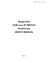
Front View
No. Component Description
1
Power LED Illuminates when the KVM switch is powered on
2
Port LEDs Port LEDs will illuminate in colors corresponding to the status of the port:
Green – Illuminate green when the corresponding port is connected and powered-on
Red – Illuminate red when the corresponding port is selected as having the KVM’s focus, but is either not
connected to a computer/server or is connected to a computer/server that is not powered-on
Orange – Illuminate orange when the corresponding port is connected, powered-on and selected as having the
KVM’s focus
Note: The Port LEDs are steady under normal conditions, but will flash at half second intervals when the
corresponding port is being accessed under Auto Scan Mode or Skip Mode.
3
LAN LEDs The Primary (Link 1) and Secondary (Link 2) LAN LEDs will illuminate in colors corresponding to the
network transfer rate:
Red – Illuminate red at speeds of 10 Mbps
Orange – Illuminate orange at speeds of 100 Mbps
Green – Illuminate green at speeds of 1000 Mbps
4
USB Ports
Note: Only computers connected to the KVM by a B055-001-USB-V2 can access the KVMs Virtual Media
functionality. Additional USB ports support external keyboard and mouse, as well as virtual media functionality.
5
Reset Switch
Note: This recessed switch must be pushed with a thin object, such as the end of a paper clip or a ballpoint pen.
• Pressing and releasing the Reset Button when the KVM switch is running performs a system reset.
• Pressing and holding the Reset Button in for more than three seconds when the KVM switch is running resets
the switch configuration to the factory default settings. Note: This does not clear User Account information.
• Pressing and holding the Reset Button in while powering on the switch will restore the KVM switch to its
original firmware in the event of a firmware upgrade failure. Note: This operation should only be performed
in the event of a firmware upgrade failure that results in the device becoming inoperable.
6
Port Switching Buttons • Press the Port Down button to switch from the current port to the previous port on the installation.
• Press the Port Up button to switch from the current port to the next port on the installation.
Note: The figure shows the front panel of a B064-032-04-IPG. The B064-032-02-IPG, B064-016-02-IPG and B064-016-04-IPG contain all the
same front-panel features as the B064-032-04-IPG, except the B064-016-04-IPG and B064-016-02-IPG come with 16 ports instead of 32.

3
4 6 7 85
1
2
6
Introduction (continued)
Components (continued)
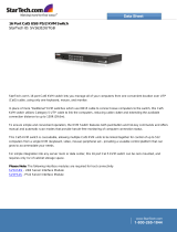
Rear View
No. Component Description
1
Power Sockets (C6) The two C6 power sockets are located here. Connect the included power cords (C5 to 5-15P) from here to an
appropriate power source. Note: To help protect your system from sudden, transient increases and decreases
in electrical power, it is recommended that you plug your devices into a Tripp Lite surge suppressor, line
conditioner or uninterruptible power supply (UPS).
2
Power Switchs The On/Off switches for the two power supplies are here. They are marked 1 and 2. Switch 1 is for the power
supply on the top and switch 2 is for the power supply on the bottom.
3
Secondary LAN Port
(LAN 2)
The cable that connects the KVM switch to the backup network plugs in here.
4
Primary LAN Port
(LAN 1)
The cable that connects the KVM switch to the primary network plugs in here.
5
Grounding Terminal Connect the included grounding wire to this terminal to ground the KVM switch.
6
Modem Port An optional dial-in connection is available for use in the event the KVM switch is not available over the Primary
or Secondary networks.
7
Local Console Port The included USB – PS/2 Console Cable Kit plugs in here. You can connect a local console with either a USB or
PS/2 Keyboard and Mouse.
8
Server Ports Cat5e/6 cable connects between these ports and the SIUs to connect computer/servers to the KVM switch.
Note: The figure above shows the rear panel of a B064-032-04-IPG or B064-032-02-IPG. The B064-016-04-IPG and B064-016-02-IPG differ
in that it only has a single block of 16 KVM ports.

7
Hardware Setup
General Safety Instructions
• Read all of these instructions. Save them for future reference.
• Follow all warnings and instructions marked on the device.
• Use of this equipment in life support applications where failure of this equipment can reasonably be expected to cause the failure of the life
support equipment or to significantly affect its safety or effectiveness is not recommended. Do not use this equipment in the presence of a
flammable anesthetic mixture with air, oxygen or nitrous oxide.
• This device is designed for IT power distribution systems with up to 230V phase-to-phase voltage.
• Do not place the device on any unstable surface (cart, stand, table, etc.). If the device falls, serious damage will result.
• Do not use the device near water.
• Do not place the device near, or over, radiators or heat registers.
• The device cabinet is provided with slots and openings to permit adequate ventilation. To ensure reliable operation and protect against
overheating, these openings must never be blocked or covered.
• The device should not be placed on a soft surface (bed, sofa, rug, etc.), as this will block its ventilation openings. Likewise, the device should
not be placed in a built-in enclosure unless adequate ventilation has been provided.
• Never spill liquid of any kind on the device.
• Unplug the device from the wall outlet before cleaning. Use a damp cloth for cleaning. Do not use liquid or aerosol cleaners.
• The device should be operated from the type of power source indicated on the marking label. If you are not sure of the type of power available,
consult your dealer or local power company.
• To prevent damage to your installation, ensure that all devices are properly grounded.
• The device is equipped with a 3-wire grounding type plug. This is a safety feature. If you are unable to insert the plug into the outlet, contact
your electrician to replace your obsolete outlet. Do not attempt to defeat the purpose of the grounding-type plug. Always follow your local/
national wiring codes.
• Position system cables and power cables carefully to ensure that nothing rests on any cable. Route the power cord and cables so that they
cannot be stepped on or tripped over.
• If an extension cord is used with this device, make sure that the total ampere rating of all products used on the cord does not exceed the
extension cord ampere rating. Make sure that the total of all products plugged into the wall outlet does not exceed 15 amperes.
• To help protect your system from sudden transient increases and decreases in electrical power, it is recommended that you plug your devices
into a Tripp Lite surge suppressor, line conditioner, or uninterruptible power supply (UPS).
• When connecting or disconnecting power to hot-pluggable power supplies, observe the following precautions:
> Install the power supply before connecting the power cable to the power supply
> Unplug the power cable before removing the power supply
> If the system has multiple sources of power, disconnect power from the system by unplugging all power cables from the power supplies
> Never push objects of any kind into or through cabinet slots. They may touch dangerous voltage points or short out parts, resulting in a risk
of fire or electrical shock
> Do not attempt to service the device yourself. Refer all servicing to qualified service personnel
• If the following conditions occur, unplug the device from the wall outlet and bring it to qualified service personnel for repair:
> The power cord or plug has become damaged or frayed
> Liquid has been spilled into the device
> The device has been exposed to rain or water
> The device has been dropped or the cabinet has been damaged
> The device exhibits a distinct change in performance, indicating a need for service
> The device does not operate normally when the operating instructions are followed
• Adjust only those controls that are covered in the operating instructions. Improper adjustment of other controls may result in damage that will
require extensive repair work by a qualified technician.
• Do not connect the RJ11 connector marked “UPGRADE” to a public telecommunication network.

Use the M3x8 Phillips head hex screws
provided with the rack mount kit
Use user supplied
hardware to attach
to the rack
8
Hardware Setup (continued)
Rack Mounting Safety Instructions
• Before working on the rack, make sure that the stabilizers are secured to the rack, extended to the floor, and that the full weight of the rack
rests on the floor. Install front and side stabilizers on a single rack or front stabilizers for joined multiple racks before working on the rack.
• Always load the rack from the bottom up, and load the heaviest item in the rack first.
• Make sure that the rack is level and stable before extending a device from the rack.
• Use caution when pressing the device rail release latches and sliding a device into or out of a rack; the slide rails can pinch your fingers.
• After a device is inserted into the rack, carefully extend the rail into a locking position, and then slide the device into the rack.
• Do not overload the AC supply branch circuit that provides power to the rack. The total rack load should not exceed 80 percent of the branch
circuit rating.
• Make sure that all equipment used on the rack, including power strips and other electrical connectors, is properly grounded.
• Ensure that proper airflow is provided for devices in the rack.
• Ensure that the operating ambient temperature of the rack environment does not exceed the maximum ambient temperature specified for the
equipment by the manufacturer.
• Do not step on or stand on any device when servicing other devices in a rack.
The KVM switch can be placed on any level surface that can safely support its weight plus the weight of attached cables. When placing the KVM
switch on a desktop, remove the backing material from the rubber feet that came with this package and affix them to the switch’s bottom panel at
the corners.
Note: To ensure adequate ventilation, allow at least 5 cm on each side, and 13 cm at the back for power cord and cable clearance.
The KVM switch can be mounted in a 19-in (1U) rack. The rack mount brackets can be installed on either the front or the back of the unit so that
it can be mounted to the front or back of the rack.
1. Depending on whether you front-rack mount or rear-rack mount the unit, remove the two screws located on both sides of the front or back of
the unit.
2. Use the screws supplied with the rack mount kit to attach the rack mount brackets to the front or rear of the unit.
3. Position the device in the front or rear of the rack and align the holes in the mount brackets with the holes in the rack.
4. Secure the rack mount brackets to the rack using user-supplied screws.
In a single-stage installation, there are no additional KVM switches cascaded or daisy-chained from the B064-Series KVM. To set up a single-
stage installation, refer to the following instructions and the corresponding installation diagrams.
1. Make sure that power to all the devices you will be connecting, including all pre-existing devices on the installation, have been turned off.
2. Optional: Plug your Local Console’s keyboard, monitor, and mouse into the KVM’s Local Console Ports. You will need to connect the
included USB – PS/2 Console Cable Kit to the console port on the back of the unit.
Note: You can use any combination of keyboard and mouse connections. For example, you can use a PS/2 keyboard with a USB mouse. USB
keyboards and mice can plug into the USB ports on the front panel, as well as the ports on the USB – PS/2 Console Cable Kit. The B064-Series
KVM Switch does not support distances above 65 ft between the KVM and the local monitor.
3. Use Cat5e cable to connect any available KVM port to a Server Interface Unit (SIU). See the chart in the Server Interface Unit section to
determine the appropriate SIU.
4. Connect the Server Interface Unit to the computer/server.
5. Connect a Cat5e cable from the network into the KVM switch’s primary network port (LAN 1).
6. Optional: Connect a second Cat5e cable from the network into the KVM switch’s backup (secondary) network port (LAN 2).
Stacking
Rack Mounting
Single-Stage Installation

2
4
6
9
8
5
7
2
3
3
9
7. Optional Dial-In Modem Connection: Use Cat5e cable to connect the KVM switch’s Modem port to the included RJ45 to DB9 Adapter, and
connect the adapter’s DB9 connector to the modem’s DB9 port.
8. Use the included grounding wire to ground the unit. Connect one end of the wire to the grounding terminal, and the other end of the wire to a
suitable grounded object.
9. Plug the included power cords into the KVM switch’s Power Sockets, and then into a Tripp Lite Surge Suppressor, Uninterruptible Power
Supply (UPS) or PDU.
10. Turn on the power to the KVM switch. Once it is powered up, turn on the power to the connected computers.
Single-Stage Installation (continued)
Two-Stage Installation
Hardware Setup (continued)
Up to 32 additional B064-016 KVM switches can be cascaded from your unit’s KVM ports, expanding the number of connected computers/
servers up to 256. In a cascaded installation, the top KVM Switch is considered the first-stage unit, the cascaded switches are considered second-
stage units.
To set up a two-stage installation:
1. Ensure that power to all the devices you will be connecting, including all pre-existing devices on the installation, have been turned off.
2. Use Cat5e/6 cabling to connect an available KVM port on the first-stage unit to a B054-001-PS2 or B055-001-PS2 SIU.
Note: Although USB SIUs will allow you to cascade to a second-stage KVM, only PS/2 SIUs will properly display the cascaded KVM in the
OSD. When connected via PS/2 SIU, the cascaded KVM will be displayed as an expandable port, allowing you to easily access the connected
computers. When connected via USB SIU, the cascaded KVM will be displayed as an ordinary port. To access computers connected to the KVM,
you will have to use the cascaded KVMs OSD.
3. Plug the SIU’s KVM connectors to the Keyboard, Video, and Mouse Console ports of the second-stage B064-016 unit.
Note: The distance between the second-stage unit and the first-stage Unit cannot exceed 164 ft. (50m).
4. Use the appropriate KVM Cable Kits (See the Second Stage KVMs owner’s manual), to connect any available KVM port on the second-stage
unit to the Keyboard, Video and Mouse ports of the computer/server you are installing.

10
The B064-Series KVM Switches support hot plugging: components can be removed and added back into the installation by unplugging and
replugging their cables from the ports without the need to shut the unit down. The KVM also includes an Adapter ID function that stores the port
settings of the SIU (Port OS, OS Language, etc.), allowing you to switch an SIU and its connected computer to a new port without having to re-
enter its port settings. The settings are stored by SIU only; therefore, the correct settings will not transfer if you change the computer connected
to the SIU. Also, the Adapter ID function only applies when switching to ports on the same KVM switch.
If it becomes necessary to power off the B064-Series KVM Switch, or the switch loses power and needs to be restarted, wait 10 seconds before
powering it back on. Connected computers should not be affected by this but if any of them should fail, simply restart them.
Each computer on the installation is assigned a unique Port ID. The Port ID is a one or two segment number that is determined by the Stage Level
and KVM port number of the KVM switch to which the computer/server is connected.
Single-Stage Installations
Single-stage installations will have a one segment Port ID consisting of two digits.
(For example, a computer/server connected to port 19 of a B064-032-04-IPG will have a Port ID of 19. A computer/server connected to port 9 of
a B064-032-04-IPG will have a Port ID of 09)
Two-Stage Installations
Two-stage installations will have a two segment Port ID consisting of 4 digits. (2 digits per segment)
• The first segment of the Port ID represents the port number of the first-stage KVM switch to which the cascaded unit is connected.
• The second segment of the Port ID represents the port number of the second-stage KVM switch to which the computer/server is connected.
(For example, a computer attached to port 3 of a second-stage KVM switch that is connected to port 15 of the first-stage KVM switch will have a
Port ID of 03-15)
Two-Stage Installation (continued)
Hot Plugging
Powering Off & Restarting
Port ID Numbering
Hardware Setup (continued)
5. Plug the power cord that came with the cascaded KVM switch into its power socket, and then into a Tripp Lite Surge Suppressor,
Uninterruptible Power Supply (UPS) or PDU.
6. Repeat these steps for any other second-stage units you wish to connect.
7. First power on the first-stage KVM Switch and then power on all second-stage KVM switches.
8. Turn on the power to all of the connected computers/servers.
Note: The Power On sequence requires that the first-stage KVM Switch be powered on first. After the first-stage KVM Switch has been powered
on, all second-stage units must be powered on. After the second-stage units have been powered on, the connected computers/servers can be
powered on.

11
The B064-Series KVM Switches supports three types of users:
User Type Description
Super Administrator
Super Administrators have full access to all Ports and Devices in the KVM installation. They can manage all aspects of the
installation.
Administrator
Administrators have access to Ports and Devices that are authorized by the Super Administrator. They can manage Users
and Groups and configure their personal working environment.
User
Users can access Ports and Devices authorized by Super Administrators or Administrators and they can configure their
personal working environment.
First Time Setup
Network Setup - IP Address Determination
Super Administrator Setup
Once the B064-Series KVM Switch has been installed, the Super Administrator must prepare the unit up for user operation by setting the
network parameters and adding users.
If you are an administrator logging in for the first time, you must
access the B064-Series KVM Switch in order to give it an IP address
to which users can connect. B064-Series KVM switches support both
standard IPv4 and IPv6. There are three methods of doing this: Local
Console, IP Installer and Browser.
1. Local Console
After the local console has been connected and the B064-Series KVM
Switch is turned on, a login prompt appears on the console monitor:
Log in using the default Username: administrator and Password:
password. For security purposes, it is strongly recommended that you
change these to a unique Username and Password. (See Changing the
Super Administrator Login section for instructions.)
After you successfully log in, the Local Console Main Screen
appears:
1. Click the Device Management icon at the top of the screen.
2. On the screen that appears on the right-hand side of the page select
the Network tab.

Super Administrator Setup (continued)
Network Setup - IP Address Determination (continued)
12
NIC Settings
The B064-Series KVM Switch has two network interfaces. The NIC
Setting section of the Network tab allows you to assign a single IP
Address and DNS Server for both network interfaces, or to assign a
separate address for each.
Redundant NIC
If Redundant NIC is enabled (the default), both interfaces use the IP
address assigned to Network Adapter 1. Under this configuration, the
B064-Series KVM Switch will switch to the second network interface
in the event there is a crash on the first network interface.
• If you select Redundant NIC, the Network Interface drop-down
menu will be frozen to Network Adapter 1, and you will only have
to enter IP Address and DNS Server settings once.
• If you do not select Redundant NIC, you will have to enter IP
Address and DNS Server settings for both Network Adapter 1 and
Network Adapter 2. User the Network Interface drop-down menu to
select the Network Adapter you want to configure.
IP Address and DNS Server Address
The B064-Series KVM switch supports both IPv4 and IPv6
addresses. The Network page allows you to set the IP address
manually, or to select to have it automatically assigned via DHCP
server. By default, the IP address is set to be assigned automatically
via DHCP server.
• To have the IP address assigned by your DHCP server, check the
Obtain IP address automatically check box in the IPv4 or IPv6
settings section, depending on your network.
• To assign an IP address yourself, check the Set IP address manually
check box in the IPv4 or IPv6 settings section, depending on your
network. When checked, the IP address and DNS server address
fields open up, allowing you to enter in the desired settings. Once
you have entered in all the IP address and DNS server address
information, click the Save button at the bottom of the screen. Upon
logging out of the KVM (click the Logout icon in the upper-right
corner of the OSD), the KVM will reset itself and the IP address
settings you just entered will be implemented.
Note: When manually assigning a DNS Server address, it is required
that you enter the Preferred DNS server, but the Alternate DNS server
is an optional field.
See Network section under Device Management for more information
on these settings.
2. IP Installer
For computers running Windows, an IP address can be assigned with
the IP Installer utility:
Note: In order to use the IP Installer, the IP Installer Enabled check
box in the Network page must be checked. (See Network section
under Device Management in OSD Operation for details.) By default,
the IP Installer View Only check box is checked, allowing you to view
the KVMs IP Address using the IP Installer but not change it.
1. Obtain the IP Installer file from the CD that came with the B064-
Series KVM Switch and save it to a desired location on a computer
that is on the same network as your B064-Series KVM Switch.
2. Go to the IP Installer file that you just saved and run the IPInstaller.
exe file.
3. Select the B064-Series KVM Switch in the Device List.
Note: If the list is empty, or your device doesn’t appear, click
Enumerate to refresh the Device List. If there is more than one device
in the list, use the MAC address to pick the one you want. The B064-
Series KVM Switches MAC address is located on its bottom panel.
4. From here you can choose to Obtain an IP address automatically
(DHCP), or Specify an IP address. If you choose to assign your
own address, fill in the IP Address, Subnet Mask, and Gateway
fields with information appropriate to your network.
5. Click Set IP.
6. After the IP address shows up in the Device List, click Exit.
3. Browser
By default, the KVM switch is set to have its IP address assigned
automatically via DHCP server. If the KVM is connected to a network
without a DHCP server, it boots with a default IP address. On IPv4
networks, the default IP is 192.168.0.60. If the KVM is on an IPv6
network, the default IP address is determined by the KVMs MAC
address. For example, if the KVM has a MAC address of 00-10-74-13-
81-01, the IPv6 address is FE80:0:0:0:0010:74FF:FE13:8101. The
parts of the IP address that are bolded and underlined are fixed.
1. Access the B064-Series KVM switch by using the default URL
mentioned above.
2. Assign a fixed IP address for the KVM using the same instructions
as described in the Local Console section of this chapter.

13
Super Administrator Setup (continued)
Logging Into the B064-Series KVM Switch
Local Console Login
Changing the Super Administrator Login
To change the default Super Administrator Username and Password,
do the following:
1. At the top of the OSD page, click User Management.
Since this is the first time the page is being accessed, only the Super
Administrator appears:
2. Click Administrator in the left panel; or, select Administrator in the
central panel and click the Modify button at the bottom of the page.
The User Information page appears:
3. Change the Username and Password to something unique.
4. Re-enter the password to confirm it is correct.
5. Click Save.
6. When the dialog box informing you that the change completed
successfully appears, click OK.
The B064-Series KVM Switches can be accessed in the following ways: via local console, an internet browser, the AP Windows Client and/or
the AP Java Client. Operating the KVM switch and configuring its settings is done the same regardless of how you connect to the B064-Series
KVM Switch; the only difference is the way in which you establish the connection. This chapter describes the login procedures for each of these
methods.
The local console login dialog box is displayed once the installation is complete. Simply key in your Username and Password and click Login to
bring up the OSD Main Page.
Note: If you supply an invalid login, the authentication routine will return an Invalid Username or Password message. If you see this message,
log in again being careful to enter the correct Username and Password.

14
Logging Into the B064-Series KVM Switch (continued)
Browser Login
The B064-Series KVM Switches can be accessed via Internet browser
from any platform that has the Java Runtime Environment 6, Update
3, or higher installed. If you don’t already have the required JRE
installed, it is available for free download from the Java web site:
www.java.com
Note: Windows 7 users must run Internet Explorer as an
administrator for the Active X control to work properly. If you don’t
run Internet Explorer as an administrator, you will not be able to
access the connected computers.
To access the switch via browser, do the following:
1. Open the browser and specify the IP address of the B064-Series
KVM Switch you want to access, as given to you by your system
administrator.
Note: For security purposes, a login string may have been set by the
administrator. If so, you must include a forward slash and the login
string along with the IP address when you log in. (For example, a
computer with a login string of B064-032-04-IPG would have a URL
such as 192.168.0.100/B064-032-04-IPG)
2. When you try to log into the device from your browser, a Security
Alert message appears to inform you that the device’s certificate is
not trusted, and asks if you want to proceed. The certificate can be
trusted, but the alert is triggered because the certificate’s name is
not found on Microsoft’s list of Trusted Authorities.
You have two options:
• If you are working on a computer other than your own, accept the
certificate for just this session by clicking Yes.
• If you are working at your own computer, install the certificate.
After the certificate is installed, it will be recognized as trusted. To
install the certificate, do the following:
a) In the Security Alert dialog box, click View Certificate. The
Certificate Information dialog box appears.
Note: You may need to run Internet Explorer as an Administrator
in order to view and install the certificate.
b) Click Install Certificate.
c) Follow the Installation Wizard to complete the installation.
Unless you have a specific reason to choose otherwise, accept the
default options.
d) When the Wizard presents a caution screen, click Yes.
e) Click Finish to complete the installation and click OK to close
the dialog box. The certificate is now trusted.
Upon installing the certificate or accepting the unrecognized
certificate for the current session, the browser login dialog box
appears.
3. Provide a valid Username and Password (set by the KVM switch’s
administrator), and click Login to bring up the OSD Main Page.
Note: If you supply an invalid login, the authentication routine will
return an Invalid Username or Password message. If you see this
message, log in again being careful to enter the correct Username
and Password.
AP Windows Client Login
In some cases, the Administrator may not want the B064-Series KVM
Switches to be available via browser. The Windows AP Client allows
Windows systems users access to the KVM switch without having to
go through a browser.
The AP Windows Client can be found in the Download Section of the
OSD or on the CD that came with your B064-Series KVM Switch.
If you do not have access to the CD, and browser access to the KVM
switch has already been disabled, you will need to obtain the file from
your system administrator. Once you have saved the AP Windows
Client, go to its location and double-click the WinClient.exe icon to
bring up the Windows Client Connection Screen.
Note:
1. If you have trouble opening the AP Windows Client, save it to your
desktop and try again.
2. When accessing the AP Windows Client for the first time, you will
be prompted to provide a serial number. This serial number can be
found on the CD that came with your KVM.

15
Logging Into the B064-Series KVM Switch (continued)
AP Java Client Login
AP Windows Client Login (continued)
In those cases in which the Administrator does not want the B064-Series KVM Switch to be available via browser and the remote user is not
running Windows, the AP Java Client provides access to the KVM switch.
After downloading the AP Java Client, go to the location on your hard disk where you downloaded the program and double-click on it to bring up
the connection screen. The AP Java Client connection screen is the same as the Windows version, except that it does not contain a menu bar with
File and Help menus. Note: When accessing the AP Java Client for the first time, you will be prompted to provide a serial number. This serial
number can be found on the CD that came with your KVM.
The Connection Screen
A description of the contents of the Connection Screen is given in the following table:
Item Description
Menu Bar The Menu Bar contains two menus; File and Help. The File Menu allows the operator to Create, Save, and Open Work files.
Server List
Each time the WinClient.exe file is run, it searches the User’s LAN segment for B064-Series KVM Switches, and lists the ones
it finds in this box. Double-click on any of the units in this list to connect to it.
Note: For a switch to show up in the Server List, the Enable Device List check box in the Operating Mode page (see Operating
Mode section under Device Management in OSD Operation for details) must be checked and the Program service port in the
Network page (see Network section under Device Management in OSD Operation for details) must be set to the same number
as in the AP Windows Client Port field.
Server
This area is used when you want to connect to a B064-Series KVM Switch at a remote location.
• Click on the IP drop-down and select an address from the list. If the address you want is not listed, key in the target IP
address in the IP field, and its port number in the Port field.
• When the IP address and port number have been specified, click Connect to bring up a login dialog box. Provide a
Username and Password as provided by your system administrator and click OK to establish a connection with the B064-
Series KVM Switch.
• When you have finished with your session, click Disconnect to end the connection.
Message List Lists status messages regarding the connection to the B064-Series KVM Switch.
Switch to Remote
View
Once a remote connection with a B064-Series KVM Switch has been established, this button becomes active. Click it to switch
to the KVM Switch’s Main OSD Page.
The File Menu
The File Menu allows the operator to Create, Save, and Open Work Files. A Work File consists of all the information specified in a Client session.
This includes the items in the Server List and Server IP List.
Whenever a user runs the Client program, it opens with the values contained in the current Work File, i.e. the values that were in effect when the
program was last closed.
The File menu consists of three items:
Item Description
New Allows the user to create a named work file so that its values will not be lost and will be available for future use
Open Allows the user to open a previously saved work file and use the values contained in it
Save Allows the user to save the values presently in effect as the current work file
Exit Exits the AP Windows Client
1. If your KVM is displayed in the Server List, connect to it by highlighting it and
clicking on the Connect button. Note: For a switch to show up in the Server List,
the Enable Device List checkbox in the Operating Mode page (see Operating Mode
section under Device Management in OSD Operation for details for details) must be
checked and the Program server port must match what is set in the Network page (See
Network section under Device Management in OSD Operation for details.)
2. If your KVM does not display in the Server List, enter in its IP address in the IP
server field and click the Connect button.
3. Upon clicking the connect button, you will be prompted to enter your username and
password. Enter in your username and password and press OK.
4. When connected, the Remote View button will be activated. Click on it to access the
KVM remotely. Click on the Disconnect button to log out of the KVM switch.

16
OSD Operation
After logging into the KVM switch, the OSD Main Page appears.
Depending on how you logged into the switch, the interface will vary
slightly. The following section describes the differences between these
interfaces and the icons and functions you will find in them.
Web Browser Main Page
When logging into the KVM switch via web browser, the following
page is displayed.
The following chart describes the components of this page.
No. Component Description
1
Tab Bar
The Tab Bar consists of category icons that take
you to the various interfaces used to operate
the KVM switch. The icons that are displayed in
the Tab Bar depend on your user type (Super
Administrator, Administrator, User), your
permissions and the method you use to log into
the KVM switch.
2
Menu Bar
The Menu Bar consists of sub-categories of the
selected category icon. As with the Tab Bar, the
sub-categories that show up in the Menu Bar
depend on your user type and permissions.
3
Sidebar
The Sidebar displays a Tree Diagram that lists
all of the functions available for the chosen
category and sub-category. Clicking on
one of the Sidebar functions will pull up the
corresponding interface in the Interactive Display
Panel. At the bottom of the Sidebar is a Filter
button that allows you to display only the parts
of the Tree Diagram that you filter for. (See Filter
section under Connections in OSD Operation for
details.)
4
About
Clicking on this icon pulls up the KVM switches
firmware version
5
Logout
Clicking on this icon logs you out of the KVM
switch
6
Welcome
Message
When enabled (see User Preferences section
under OSD Operation for details), this section of
the main page will display a welcome message.
This is disabled by default.
7
Interactive
Display
Panel
This is the main work area of the OSD. Different
interfaces are displayed here depending on your
category, sub-category and sidebar selections.
AP Client Main Page
When logging into the KVM switch via the non-browser AP Windows
or Java client, the following page is displayed.
The AP Client Main Page differs from the Web Browser Main Page as
follows:
• Instead of a Menu Bar, the AP Client Main Page has a set of
notebook tabs that are used to select sub-categories. As with the
Web Browser Main Page, the notebook tabs displayed depend on
the user type and permissions.
• In addition to the Filter button at the bottom of the Sidebar, there is
a Scan button and an Array Mode button.
• There is a hidden Control Panel (see Control Panel section under
Remote Session Operation for details) at the upper center of the
screen that becomes visible when you mouse over it.
• In addition to the two icons in the upper-right corner of the Web
Browser Main Page, there is a third icon that closes the OSD and
displays the screen of the last selected port.
The OSD can be navigated via keyboard using the commands in the
table below:
Command Description
Ctrl + P Opens the Port Access category page
Ctrl + U Opens the User Management category page
Ctrl + C Opens the Device Management category page
Ctrl + L Opens the Log category page
Ctrl + M Opens the Maintenance category page
Ctrl + D Opens the Download category page
F1 Displays the KVM switches firmware version
F2 Press to edit the name of the selected port
F4 Selects the Sidebar panel
F5 Selects the Interactive Display Panel
F7
Closes the OSD and displays the screen of the last
selected port
F8 Logs you out of the KVM switch
The OSD Main Page
2
3
7
4 561

17
OSD Tab Bar
The number and type of icons that appear on the tab bar at the top of the page are determined by user type (Super Administrator, Administrator
or User) and the permissions assigned when the account was created. The functions associated with each of the icons are explained in the
following table:
Icon Description
Port Access: This page is used to access and control the devices on the KVM switch installation. This page is available to
all users.
User Management: This page is used to create and manage Users and Groups, and to assign devices to them. This page
is available to Super Administrator and Administrators, ordinary users will not have access to it.
Device Management: This page is used by the Super Administrator to configure and control the overall operation of the
KVM switch. This page is available to Super Administrators or Administrators/Users who have been given access.
Log: This page displays the contents of the log file. (See Log section under OSD Operation for details.)
Maintenance: This page is used to install new versions of the B064-Series KVM Switch firmware. This page is available to
Super Administrators or Administrators/Users who have been given access.
Download: Users with appropriate permission can click this icon to download the AP Windows Client, the AP Java Client
and the Log Server. This page is available to all users, although what downloads a User can access is determined by the
Super Administrator or Administrator. Note: The Download icon is not available via the local console.
There are three small icons in the upper right-hand corner of the page. Their functions are described in the following table:
Icon Description
Click this icon to close the OSD page and return to the display of the last selected port.
Note: This icon is not available in the Web Browser Main Page.
Click this icon to display the firmware version of the B064-Series KVM Switch.
Click this icon to log out and end your B064-Series KVM Switch session.
OSD Operation (continued)
The OSD Main Page (continued)
Local Console Main Page
The Local Console Main Page is the same as the AP Client Main Page except that the Downloads icon in the tab bar is not available.
The Port Access section of the OSD is where users can access KVM ports, and control settings that directly affect that access. The sub-sections
contained in the Port Access section are described in the pages that follow.
Port Access

18
OSD Operation (continued)
Connections
The OSD Main page is the same screen that you get when navigating
to the Connections sub-section of the Port Access section. From this
page you can connect to the KVM ports.
All switches and their ports, including cascaded KVM switches, are
listed in a tree structure in the panel at the left of the screen:
When accessing a port for the first time via web browser, users will
experience a series of prompts:
Internet Explorer
When logging onto the KVM switch via Internet Explorer, the default
viewer is the Windows ActiveX viewer. To use the Java Viewer when
accessing the KVM switch via Internet Explorer, you need to update the
Viewer setting in the User Preferences page (See User Preferences section
under OSD Operation for details).
Note: Windows 7 users must run Internet Explorer as an administrator for
the Active X control to work properly. If you don’t run Internet Explore as
an administrator, you will not be able to access the connected computers.
1. When using the Windows ActiveX Viewer and clicking on a port for
the first time, a screen will open up and you will be prompted to install
the Windows ActiveX control. Click on the prompt and choose to install
the ActiveX control. Note: The screen that opens up may display a page
that says the web pages certificate can not be trusted. If this is the case,
click on the option to continue to the web page anyway.
2. When you install the ActiveX control, you may be prompted to resend
the information in order to display the web page. Click Retry.
3. Lastly, you will be prompted to install the software. Click Install.
Non-Windows Browser
When using a non-Windows browser, you will automatically be connected
to remote computers using the Java Viewer.
1. When clicking on a port for the first time, you will be prompted to run
the Java Viewer. Click ok. (To avoid this prompt every time you access a
port, check the checkbox next to Do this automatically for files like this
from now on.)
2. You will then be prompted to run the Java Viewer, and trust the
publisher (Tripp Lite). Click Run.

19
OSD Operation (continued)
Port Configuration
When accessing the KVM via AP Windows or Java Client, right-
click on any port in the Sidebar to configure a connected computer or
switch. (This feature is not available when accessing the OSD via web
browser.) A list with options pops up. Listed items vary depending on
user type and whether a cascaded KVM switch or a computer/server
port was selected. Available configuration items are:
Item Access Type Description
Expand/ Collapse Super Administrators, Administrators and
Users
• If the device’s ports are not displayed, the dialog box entry is Expand.
Click Expand to open the tree and display the ports.
• If the device’s ports are displayed, the dialog box entry is Collapse. Click
Collapse to close the tree view.
Note: This item is only active for KVM switches that have child devices
connected to them. This has the same effect as clicking the Plus (+) or
Minus (-) in the tree view.
Rename Super Administrators, Administrators
and Users
For convenience, especially in large installations with many switches and
ports, each port can be given a unique name. Note: Administrators and
Users must be given configuration access to a KVM or computer port to
be able to edit the port name. (See Device Assignment section under User
Management in OSD Operation for details.)
Copy Super Administrators, Administrators
and Users
This item is only available for ports with computers/servers connected
to them. It is used when creating a Favorites bookmark. (See Adding a
Favorite section under Favorites in OSD Operation for details.)
Properties Super Administrators and Administrators This item allows you to configure the properties of the port.
• For the master KVM switch, clicking this item
takes you to the Device Management page.
• For ports with computers/servers connected to them, a dialog box opens
allowing you to update the properties for the connected computer/server.
(See Port Properties section under Connections in OSD Operation for
details.)
Port Naming
For convenience, especially in large installations with many KVM switches and ports, each port can be given a unique name. To assign, modify
or delete a port name, follow the instructions below. Note: Administrators and Users must be given configuration access to a KVM or computer
port to be able to edit the port name. (See Device Assignment section under User Management in OSD Operation for details.)
1. Click once on the port you want to edit to highlight it, wait one second and click on it again. Note: This is not a double-click; it involves two
separate clicks. Double-clicking will switch you to the device attached to the port.
You can also right-click on the port you want to edit and select Rename in the popup box that appears (non-browser clients only).
After a second or two, the display changes to provide a text input box.
2. Key in a name for the port (or change/delete a previous one). The maximum number of characters allowed for a port name is 20. You can use
any combination of letters, numbers, and symbols on the typewriter keys of keyboards with PC US English layout.
3. When you have finished editing the port name, press [Enter] or click anywhere outside of the input box to complete the operation.
The Port Selection List
• Users only see the switches and ports they have been given access to.
• Ports and cascaded KVM switches are located under their parent
switches. Click the Plus (+) in front of a switch to expand the tree
and see the ports underneath it.
Note: In order for a cascaded B064-016 to show up as an
expandable KVM in the port list, you must use a PS/2 SIU to
cascade it from the first-level KVM. If you use a USB SIU, it will be
displayed as an ordinary port, and you will have to use the B064-
016 OSD to access computers/servers connected to it.
• When expanded, there is a Minus (-) before the KVM’s device
name. Click the Minus (-) to collapse the tree and hide the ports.
• A port’s ID number is displayed in brackets next to the port icon.
For convenience, you can give each port a unique name in addition
to this ID.
• KVM switches and ports that are on line have their monitor screen
icons lit green. The monitor screens are gray for devices and ports
that are offline.
Connections (continued)

20
OSD Operation (continued)
Port Properties
Users accessing the KVM via the non-browser clients can right-click
on a computer/server port and select Properties to configure that
port’s settings. The settings that can be changed via this dialog box
are listed in the chart below.
Note: These settings can also be changed via the Port Configuration
page. (See the Port Configuration section under OSD Operation for
details.)
Field Description
Port OS Specifies the operating system for the computer/server connected to the port. Choices are Windows, Mac, Sun, and
Other. The default is Windows.
OS Language Specifies the operating system language being used by the computer connected to the port. Click on the drop-down list
to choose from a number of languages. The default is English US.
Cable Length Specifies the length of the Cat5e cable that is being used to connect the computer to the port. Because the quality of
video decreases when using longer cable, the B064-Series KVM Switch will make adjustments to improve the video
quality based on this setting. Choices are Short (less than 32 ft.), Medium (32-82 ft.), and Long (greater than 82 ft.). The
default is Short.
Access Mode Access Mode defines how the port is to be accessed when multiple users are logged on. Choices are Exclusive,
Occupy, and Share.
Exclusive: The first user to switch to the port has exclusive control over the port. No other users can view the port. The
Timeout function does not apply to ports which have this setting.
Occupy: The first user to switch to the port has control over the port. However, additional users may view the port’s
video display. If the user who controls the port is inactive for longer than the time set in the Timeout box, port control is
transferred to the next user to move the mouse or strike the keyboard.
Share: Users simultaneously share control over the port. Input from the users is placed in a queue and executed
chronologically. Under these circumstances, users can take advantage of the Message Board. The message board
allows the user to manually take control of the keyboard and mouse only, or of the keyboard, mouse and video of a
Share port. (See Message Board section under Control Panel in Remote Session Operation for details.)
Timeout This field displays the timeout value that is set for all ports in the installation. When the port’s Access Mode has been
set to Occupy, if there is no activity from the user occupying the port for the amount of time set here, the user is timed
out and the port is released. The first user to send keyboard or mouse input after the port has been released gets to
occupy the port. As this setting is the same for all ports, you are not allowed to configure it on a port-by-port basis. This
setting can be changed using the Port Properties dialog box for the master KVM switch, which is discussed in the Port
Properties section.
After making your configuration choices, click Save to save your new settings and close the dialog box.
Connections (continued)
/