Page is loading ...

UNVENTED (VENT FREE) GAS LOG HEATER
OWNER’S OPERATION AND INSTALLATION MANUAL
MODELS VFRMV18NB, VFRMV18PB,
VFRMV24NB AND VFRMV24PB
ANSI Z21.11.2b-2008
ANSI Z21.60b-2004
APPROVED
For more information, visit www.desatech.com
— WHAT TO DO IF YOU SMELL GAS
-
O-TL REPORT
# 258-L-17-5

www.desatech.com
116412-01E2
SAFETy
-
-
-
-
-
-
-
Refer to Air for Combustion
and Ventilation
-
-
-
-
TABLE OF CONTENTS
Safety .................................................................. 2
Product Identication ........................................... 5
Local Codes......................................................... 5
Unpacking............................................................ 5
Optional Remote Control Accessories ................. 5
Product Features ................................................. 6
Air For Combustion and Ventilation ..................... 6
Installation ........................................................... 9
Operation ........................................................... 16
Inspecting Burners............................................. 20
Wiring Diagram .................................................. 20
Cleaning and Maintenance ................................ 21
Troubleshooting ................................................. 22
Specications .................................................... 26
Replacement Parts ............................................ 26
Service Hints ..................................................... 26
Technical Service............................................... 26
Accessories ....................................................... 27
Parts .................................................................. 28
Warranty ..............................................Back Cover

www.desatech.com
116412-01E 3
-
Early signs of
carbon monoxide poisoning resemble the u,
with headaches, dizziness or nausea. If you
have these signs, the log set may not be work-
ing properly. Have log
set serviced. Some people are more affected
by carbon monoxide than others. These include
pregnant women, people with heart or lung
disease or anemia, those under the inuence
of alcohol and those at high altitudes.
Natural
and Propane/LP gas are odorless. An odor-
making agent is added to the gas. The odor
helps you detect a gas leak. However, the
odor added to the gas can fade. Gas may be
present even though no odor exists.
Make certain you read and understand all
warnings. Keep this manual for reference. It
is your guide to safe and proper operation of
this log set.
-
-
-
-
SAFETy
Continued

www.desatech.com
116412-01E4
-
-
-
1. This appliance, as supplied, is only for use
with the type of gas indicated on the rating
plate. This appliance is not convertible for
use with other gases.
2.
Do not place propane/LP supply tank(s) in-
side the structure. Locate propane/LP supply
tank(s) outdoors (propane/LP units only).
3. If you smell gas
• shut off gas supply
• do not try to light any appliance
• do not touch any electrical switch; do not
use any phone in your building
• immediately call your gas supplier from
a neighbor’s phone. Follow the gas sup-
plier’s instructions
• if you cannot reach your gas supplier,
call the re department
4. This heater shall not be installed in a bed-
room or bathroom, unless installed as a
vented appliance. See Installing Damper
Clamp Accessory for Vented Operation,
page 12. This gas log set may not be
installed as a vented appliance in a bed-
room or bathroom in the Commonwealth
of Massachusetts.
5. Before installing in a solid fuel burning re-
place, the chimney ue and rebox must
be cleaned of soot, creosote, ashes and
loose paint by a qualied chimney cleaner.
Creosote will ignite if highly heated. Inspect
chimney ue for damage. If damaged,
repair ue before operating appliance.
6. If replace has glass doors, never operate
with glass doors closed, If you operate
heater with doors closed, heat buildup
inside replace will cause glass to burst.
Also if replace opening has vents at the
bottom, you must open the vents before
operating heater.
SAFETy Continued
7. To prevent the creation of soot, follow the
instructions in Cleaning and Maintenance,
page 21.
8.
Before using furniture polish, wax, carpet
cleaner or similar products, turn heater off. If
heated, the vapors from these products may
create a white powder residue within the burn-
er box or on adjacent walls and furniture.
9.
This heater needs fresh, outside air ventilation
to run properly this heater has an Oxygen De-
pletion Sensing (ODS) safety shutoff system.
The ODS shuts down the heater if enough
fresh air is not available. See Air Combustion
and Ventilation page 6. If the heater keeps
shutting off, see Troubleshooting, page 22.
10. Do not run heater
• where ammable liquids or vapors are
used or stored
• under dusty conditions
11. Do not use heater to cook food or burn
paper or other objects.
12. Do not use heater if any part has been ex-
posed to or under water. Immediately call
a qualied service technician to inspect
the room heater and to replace any part
of the control system and any gas control
which has been under water.
13. Do not operate heater if any log is broken.
Do not operate heater if a log is chipped
(dime-size or larger).
14. Turn heater off and let cool before servic-
ing, installing or repairing. Make sure the
selector switch is in the OFF position. Only
a qualied service person should install,
service or repair heater.
15. Make sure the selector switch is in the
OFF position when you are away from
home for long periods of time.
16. Remote-ready heaters shall not be con-
nected to any external electrical source.
17. Operating heater above elevations of
4,500 feet may cause pilot outage.
18. To prevent performance problems, do
not use propane/LP tank(s) of less than
100 lb. capacity (propane/LP units only).
19. Provide adequate clearances around air
openings.

www.desatech.com
116412-01E 5
PRODUCT IDENTIFICATION
Figure 1 - Product Identication
Log Set
Chassis Assembly
LOCAL CODES
Install and use the heater with care. Follow
all local codes. In the absence of local codes,
use the latest edition of the National Fuel Gas
Code ANSI Z223.1/NFPA 54*
*Available from:
American National Standards Institute, Inc.
1430 Broadway
New York, NY 10018
National Fire Protection Association, Inc.
Battery march park
Quincy, MA 02269
Note: Where listed vented decorative logs are
required, thermostat operations is not permit-
ted. The installation of appliances designed
for manufactured home (U.S. only) or mobile
home installation must conform with the
Standard CAN/CSA Z240 MH, Standard, Title
24 CFR, Part 3280, in the United States or
when such a Standard is not applicable, ANSI/
NCSBCS A225.1/NFPA 501A Manufactured
Home Installations Standard.
The installation
must be made by a licensed plumber or
gas tter in the Commonwealth of Mas-
sachusetts.
Sellers of unvented propane or natural
gas-red supplemental room heaters shall
provide to each purchaser a copy of 527
CMR 30 upon sale of the unit.
Vent-free gas products are prohibited for
bedroom and bathroom installation in the
Commonwealth of Massachusetts.
UNPACkING
-
1. Remove log set assembly from carton.
Note: Do not pick up assembly by logs.
This could damage the unit. Always
handle assembly by grate.
2. Remove all protective packaging applied
to log set for shipment.
3. Check heater for any shipping damage. If
heater is damaged call DESA Heating, LLC
at 1-866-672-6040 for replacement parts
before returning to dealer.
OPTIONAL REMOTE CONTROL ACCESSORIES
There are four optional remote controls that
can be purchased separately:
• Wall switch
• Hand-held ON/OFF remote
• Wall thermostat
• Hand-held thermostat remote
See Accessories, page 27.
The wall thermostat or hand-held thermostat
may not be used where vented decorative list-
ings is required.

www.desatech.com
116412-01E6
National Fuel Gas Code, ANSI
Z223.1/NFPA 54, the International
Fuel Gas Code,
Today’s homes are built more energy efcient
than ever. New materials, increased insulation
and new construction methods help reduce
heat loss in homes. Home owners weather
strip and caulk around windows and doors
to keep the cold air out and the warm air in.
During heating months, home owners want
their homes as airtight as possible.
While it is good to make your home energy
efcient, your home needs to breathe. Fresh
air must enter your home. All fuel-burning ap-
pliances need fresh air for proper combustion
and ventilation.
Exhaust fans, replaces, clothes dryers and
fuel burning appliances draw air from the house
to operate. You must provide adequate fresh
air for these appliances. This will insure proper
venting of vented fuel-burning appliances.
PROVIDING ADEQUATE
VENTILATION
The following are excerpts from National Fuel
Gas Code, ANSI Z223.1/NFPA 54, Air for
Combustion and Ventilation.
All spaces in homes fall into one of the three
following ventilation classications:
1. Unusually Tight Construction
2. Unconned Space
3. Conned Space
The information on pages 6 through 8 will help
you classify your space and provide adequate
ventilation.
The air that leaks around doors and windows
may provide enough fresh air for combustion
and ventilation. However, in buildings of un-
usually tight construction, you must provide
additional fresh air.
-
-11
2
and
and
If your home meets all of the three criteria
above, you must provide additional fresh air.
See Ventilation Air From Outdoors, page 8.
If your home does not meet all of the three
criteria above, proceed to Determining Fresh-
Air Flow For Appliance Location, page 7.
PRODUCT FEATURES
OPERATION
This heater is clean burning. It requires no
outside venting. There is no heat loss out a
vent or up a chimney. Heat is generated by
both realistic ames and glowing coals. This
heater is designed for vent-free operation
with ue damper closed. It has been tested
and approved to ANSI Z21.11.2 standard for
unvented heaters. State and local codes in
some areas prohibit the use of vent-free heat-
ers. This heater may also be operated as a
vented decorative (ANSI Z21.60) product by
opening the ue damper.
SAFETY DEVICE
This heater has a pilot with an Oxygen Deple-
tion Sensing (ODS) safety shut off system.
The ODS/pilot is a required feature for vent-
free room heaters. The ODS/pilot shuts off the
heater if there is not enough fresh air.
PIEZO IGNITION SYSTEM
This heater has a piezo ignitor. This system re-
quires no matches, batteries or other sources
to light heater.
AIR FOR COMBUSTION AND VENTILATION

www.desatech.com
116412-01E 7
The National Fuel Gas Code, ANSI Z223.1/
NFPA 54 denes a conned space as a space
whose volume is less than 50 cubic feet per
1,000 Btu/hr (4.8 m
3
per kw) of the aggregate
input rating of all appliances installed in that
space and an unconned space as a space
whose volume is not less than 50 cubic feet
per 1,000 Btu/hr (4.8 m
3
per kw) of the ag-
gregate input rating of all appliances installed
in that space. Rooms communicating directly
with the space in which the appliances are
installed*, through openings not furnished
with doors, are considered a part of the un-
conned space.
* Adjoining rooms are communicating only if
there are odorless passageways or ventilation
grills between them.
DETERMINING FRESH-AIR FLOW
FOR APPLIANCE LOCATION
Use this work sheet to determine if you have
a conned or unconned space.
Includes the room in which you will
install appliance plus any adjoining rooms
with doorless passageways or ventilation grills
between the rooms.
1. Determine the volume of the space (length
x width x height).
Length x Width x Height = ______ cu. ft.
(volume of space)
Example: Space size 20 ft. (length) x 16
ft. (width) x 8 ft. (ceiling height) = 2560 cu.
ft. (volume of space)
If additional ventilation to adjoining room
is supplied with grills or openings, add the
volume of these rooms to the total volume
of the space.
2. Multiply the space volume by 20 to deter-
mine the maximum Btu/Hr the space can
support.
____________(volume of space) x 20
= (Maximum Btu/Hr the space can sup-
port)
Example: 2560 cu. ft. (volume of space) x
20 = 51,200 (maximum Btu/Hr the space
can support)
3. Add the Btu/Hr of all fuel burning appli-
ances in the space.
AIR FOR COMBUSTION AND VENTILATION
Continued
Vent-free appliance _______ Btu/Hr
Gas water appliance* _______ Btu/Hr
Gas furnace _______ Btu/Hr
Vented gas appliance _______ Btu/Hr
Gas replace logs _______ Btu/Hr
Other gas appliances* + _______ Btu/Hr
Total = _______ Btu/Hr
* Do not include direct-vent gas appli-
ances. Direct-vent draws combustion
air from the outdoors and vents to the
outdoors.
Example:
Gas water appliance _______ Btu/Hr
Vent-free appliance + _______ Btu/Hr
Total = _______ Btu/Hr
4. Compare the maximum Btu/Hr the space
can support with the actual amount of Btu/
Hr used.
__________Btu/Hr (maximum the space
can support)
__________ Btu/Hr (actual amount of
Btu/Hr used)
Example: 51,200 Btu/Hr (maximum the
space can support)
73,000 Btu/Hr (actual amount of
Btu/Hr used)
The space in the previous example is a con-
ned space because the actual Btu/Hr used
is more than the maximum Btu/Hr the space
can support. You must provide additional fresh
air. Your options are as follows:
A. Rework worksheet, adding the space
of an adjoining room. If the extra space
provides an unconned space, remove
door to adjoining room or add ventilation
grills between rooms. See Ventilation Air
From Inside Building, page 8.
B. Vent room directly to the outdoors. See
Ventilation Air From Outdoors, page 8.
C. Install a lower Btu/Hr appliance, if lower
Btu/Hr size makes room unconned.
If the actual Btu/Hr used is less than the
maximum Btu/Hr the space can support,
the space is an unconned space. You will
need no additional fresh air ventilation.
40,000
33,000
73,000

www.desatech.com
116412-01E8
-
National Fuel
Gas Code, ANSI Z223.1/NFPA 54,
the International Fuel Gas Code,
VENTILATION AIR
This fresh air would come from an adjoining
unconned space. When ventilating to an
adjoining unconned space, you must provide
two permanent openings: one within 12" of
AIR FOR COMBUSTION AND VENTILATION
Continued
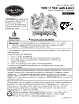
Figure 3 - Ventilation Air from Outdoors
Figure 2 - Ventilation Air from Inside
Building
Outlet
Air
V e ntilated
Attic
Outlet
A
ir
Inlet
Air
Inlet Air
V e ntilated
Crawl Space
T o
Crawl
Space
T o Attic
Or
Remove
Door into
Adjoining
Room,
Option
3
Ve ntilation Grills
Into Adjoining Room,
Option 2
Ve ntilation
Grills Into
Adjoining
Room,
Option 1
12"
12"
the ceiling and one within 12" of the oor on
the wall connecting the two spaces (see op-
tions 1 and 2, Figure 2 on page 8). You can
also remove door into adjoining room (see
option 3, Figure 2). Follow the National Fuel
Gas Code, ANSI Z223.1/NFPA 54, Air for
Combustion and Ventilation for required size
of ventilation grills or ducts.
Provide extra fresh air by using ventilation
grills or ducts. You must provide two perma-
nent openings: one within 12" of the ceiling
and one within 12" of the oor. Connect these
items directly to the outdoors or spaces open
to the outdoors. These spaces include attics
and crawl spaces. Follow the National Fuel
Gas Code, ANSI Z223.1/NFPA 54, Air for
Combustion and Ventilation for required size
of ventilation grills or ducts.
IMPORTANT: Do not provide openings for
inlet or outlet air into attic if attic has a thermo-
stat-controlled power vent. Heated air entering
the attic will activate the power vent.

www.desatech.com
116412-01E 9
INSTALLATION
-
-
-
-
IMPORTANT: Vent-free heaters add moisture
to the air. Although this is benecial, installing
heater in rooms without enough ventilation
air may cause mildew to form from too much
moisture. See Air for Combustion and Ventila-
tion, page 6.
-
-
-
-
-
-

www.desatech.com
116412-01E10
Note: If using a mantel proceed to If Using
Mantel, page 11. If not using mantel, follow
the information on this page.
You must have noncombustible material(s)
above the replace opening. Noncombustible
materials (such as slate, marble, tile, etc..)
Must be at least 1/2" thick. With sheet metal,
you must have noncombustible material be-
hind it. Noncombustible material must extend
at least 8" up (for all models). If noncombus-
tible material is less than 12", you must install
the replace hood accessory (24" Models
Only). See Figure 5, page 11, for minimum
clearances.
INSTALLATION
Continued
Figure 4 - Minimum Clearance for
Combustible to Wall
*Minimum 16" from Side Wall
*
Example
Use the correct gas type (natural or propane/
LP) for your unit. If your gas supply is not
correct, do not install in replace. Call dealer
where you bought the appliance for proper
type of appliance.
-
INSTALLATION AND CLEARANCES
FOR VENT FREE OPERATION
MINIMUM FIREPLACE CLEARANCE TO
Side Wall 16"
Ceiling 42"
Floor 5"
LOG SIZING REQUIREMENTS
Log
Height
Front
Width
Width
18" 18" 14" 30" 20.5"
24" 18" 14" 35" 24.5"
*Measured at 14" depth.
Allow adequate clearances for accessibility for
purposes of servicing and proper operation
Carefully follow the instructions below. This
will ensure safe installation into masonry,
UL127-listed manufactured replace or listed
vent-free rebox.
Ceiling
A. Clearances from the side of the replace
cabinet to any combustible material and
wall should follow diagram in Figure 4.
Example: The face of a mantel, bookshelf,
etc. is made of combustible material must
be 4" from the side of the replace to the
cabinet (see Figure 4).
B. Clearances from top of replace opening
to ceiling should not be less than 42".
-
-
Installing Damper Clamp Ac-
cessory for Vented Operation,
.

www.desatech.com
116412-01E 11
Heat Resistant
Material
(A)
Figure 5 - Heat Resistant Material (Slate,
Marble, Tile, etc.) Above Fireplace
You must have noncombustible material(s)
above the replace opening. Noncombus-
tible materials (such as slate, marble, tile,
etc.) must be at least 1/2" thick. With sheet
metal, you must have noncombustible ma-
terial behind it. Noncombustible material
must extend at least 8" up (for all models).
If noncombustible material is less than 12",
you must install the replace hood accessory
(24" Models Only). Even if noncombustible
material is more than 12", you may need the
hood accessory to deect heat away from
your mantel shelf. See Figures 5, 6 and 7, for
minimum clearances.
IMPORTANT: If you cannot meet these mini-
mum clearances, you must operate heater
with chimney ue damper open. Go to Install-
ing Damper Clamp Accessory for Vented
Operation, page 12.
MANTEL CLEARANCES
In addition to meeting noncombustible mate-
rial clearances, you must also meet required
clearances between replace opening and
mantel shelf. If you do not meet the clearances
listed below, you will need a hood.
If you meet minimum clearance between
mantel shelf and top of replace opening, a
hood is not required (see Figure 6).
If minimum clearances in Figure 6 are not met,
you must have a hood. When using a hood
there are still certain minimum mantel clear-
ances required. Follow minimum clearances
shown in Figure 7 when using hood.
INSTALLATION
Continued
Figure 6 - Minimum Mantel Clearances
Without Using Hood
Figure 7 - Minimum Mantel Clearances
When Using Hood
Minimum
Noncombustible
Material
Minimum
Noncombustible
Material Height
Distances to
Underside of
Mantel
Top of
Fireplace
Opening
Underside o
f
Mantel Shelf
12"
(A)
28" 34
1
/
2
" 38
5
/
8
" 42"
All minimum
distances
are in inches
2
1
/
2
"
6"
8"
10"
Mantel Shelf
Minimum
Noncombustible
Material
8"
Min.
14
1
/
2
" 18
5
/
8
" 22
1
/
2
"
All minimum
distances
are in inches
26"
2
1
/
2
"
6"
8"
10"
12"
Distances to
Underside of
Mantel
Hood
(GA6050,
GA6052
or GA6053)
Top of
Fireplace
Opening
Underside of
Mantel Shelf
12" or more Noncombustible mate-
rial OK.
Between 8"
and 12"
2 4" M o d el s : I n s t a ll
fireplace hood acces-
sory (GA6050, GA6052,
GA6053, see Accesso-
ries, page 27).
18" Model: Noncombus-
tible material OK.
Less than 8"
Noncombustible material
must be extended to at
least 8". See Between
8" and 12", above. If you
cannot extend material,
you must operate heater
with ue damper open and
damper clamp installed.

www.desatech.com
116412-01E12
INSTALLATION
Continued
INSTALLING DAMPER CLAMP
ACCESSORY FOR VENTED
OPERATION
Note: When used as a vented decorative,
appliance must be installed only in a solid-
fuel burning replace with a working ue and
constructed of noncombustible material.
Instal-
lation of this gas log set as a vented appliance
in the Commonwealth of Massachusetts re-
quires the damper be permanently removed
or welded in the fully open position.
If your heater is a non-thermostatically-
controlled model, you may use this heater as
a vented product. There are three reasons for
operating your heater in the vented mode.
1. The replace does not meet the clearance
to combustibles requirements for vent-
free operation.
2. State or local codes do not permit vent-
free operation.
3. You prefer vented operation.
If reasons number 1 or 2 above apply to you,
you must permanently open chimney ue
Figure 10 - Attaching Damper Clamp
Damper
Damper
Clamp
Damper
Damper
Clamp
NOTICE:
-
of the following:
-
FLOOR CLEARANCES
A. If installing appliance on the oor level,
you must maintain the minimum distance
of 14" to combustibles (see Figure 8).
B. If combustible materials are less than 14"
to the replace, you must install appliance
at least 5" above the combustible ooring
(see Figure 9).
14"
Min.
Combustible
Material
Noncombustible
Material
Hearth
5"
Min.
Combustible
Material
Figure 8 - Minimum Fireplace Clearances
If Installed at Floor Level
Figure 9 - Minimum Fireplace Clearances
Above Combustible Flooring

www.desatech.com
116412-01E 13
damper. You must install the damper clamp
accessory (to order, see Accessories, page
27). This will insure vented operation (see
Figure 10, page 12). The damper clamp will
keep damper open. Installation instructions
are included with clamp accessory.
See chart below for minimum permanent ue
opening you must provide. Attach damper
clamp so the minimum permanent ue open-
ing will be maintained at all times.
5"
6"
7"
8"
20 sq. inches
29 sq. inches
39 sq. inches
51 sq. inches
6' to 15'
15' to 30'
39 sq. inches
29 sq. inches
INSTALLING REMOTE CONTROL
If installing optional remote control accessory
you will need to install the remote accessory
bracket for the receiver.
Use screws provided to attach bracket to
valve bracket as shown in Figure 11.
Follow installation instructions included with
remote accessory.
INSTALLATION
Continued
Figure 12 - Attaching Flexible Gas Hose
to Heater Gas Regulator
Gas Control Valve
Flexible Gas
Hose (if allowed
by local codes)
Valve Bracket
Figure 11 - Attaching Remote Bracket to
Valve Bracket
Remote
Bracket
-
-
IMPORTANT: Make sure the heater burners
are level. If heater is not level, heater will not
work properly.
• control cover kit (provided with heater)
• approved exible gas hose and ttings
(provided with heater) (if allowed by local
codes)
• sealant (resistant to propane/LP gas, not
provided)
Note: Install optional HRC100 and HRC200
Receiver and Hand-Held Remote Control Kit
(see Accessories, page 27) before installing
gas log heater. See installation instructions
included with the kit.
1. Apply pipe joint sealant lightly to male
threads of gas tting (not provided). Con-
nect approved exible gas hose to inlet
side of gas control (see Figure 12).
2. Position heater assembly in replace.
3. Connect to gas supply. See Connecting
To Gas Supply, page 14.

www.desatech.com
116412-01E14
INSTALLATION
Continued
* Purchase the optional CSA design-certied
equipment shutoff valve from your dealer.
**Minimum inlet pressure for purpose of input
adjustment.
Figure 14 - Gas Connection
damage could occur. Install external regulator
with the vent pointing down as shown in Figure
13. Pointing the vent down protects it from
freezing rain or sleet.
-
CONNECTING TO GAS SUPPLY
-
Before installing heater, make sure you have
the items listed below.
• external regulator (supplied by installer)
• piping (check local codes)
• sealant (resistant to propane/LP gas)
• equipment shutoff valve *
• test gauge connection *
• sediment trap
• tee joint
• pipe wrench
• approved exible gas line with gas connec-
tor (if allowed by local codes) (provided)
* A CSA design-certied equipment shutoff
valve with 1/8" NPT tap is an acceptable al-
ternative to test gauge connection. Purchase
the optional CSA design-certied equipment
shutoff valve from your dealer.
For propane/LP units, the installer must
supply an external regulator. The external
regulator will reduce incoming gas pressure.
You must reduce incoming gas pressure to
between 11" and 14" of water. If you do not re-
duce incoming gas pressure, heater regulator
Figure 13 - External Regulator With Vent
Pointing Down
To Gas
Control
Valve
3" Minimum
Sediment Trap
- From
External Regulator
(11" W.C.** To 14"
W.C. Pressure)
- From
Gas Meter (5"
W.C.** to
10.5" W.C.
Pressure)
CSA Design-
Certied
Equipment
Shutoff Valve
With 1/8" NPT
Tap*
Approved Flexible Gas
Hose (if allowed by
local codes)
Tee Pipe
Joint Nipple Cap
Propane/LP
Supply Tank
External
Regulator
with Vent
Pointing
Down

www.desatech.com
116412-01E 15
Installation must include an equipment shutoff
valve, union and plugged 1/8" NPT tap. Locate
NPT tap within reach for test gauge hook up.
NPT tap must be upstream from heater (see
Figure 14, page 14).
IMPORTANT: Install equipment shutoff valve
in an accessible location within 6 feet of the
appliance. The equipment shutoff valve is
for turning on or shutting off the gas to the
appliance.
Apply pipe joint sealant lightly to male NPT
threads. This will prevent excess sealant from
going into pipe. Excess sealant in pipe could
result in clogged heater valves.
We recommend that you install a sediment
trap in supply line as shown in Figure 14, page
14. Locate sediment trap where it is within
reach for cleaning. Install in piping system
between fuel supply and heater. Locate sedi-
ment trap where trapped matter is not likely
to freeze. A sediment trap traps moisture and
contaminants. This keeps them from going
into heater controls. If sediment trap is not
installed or is installed wrong, heater may
not run properly.
-
-
-
der Connecting to Gas Supply
PRESSURE TESTING GAS SUPPLY
PIPING SYSTEM
1. Disconnect appliance with its appliance
main gas valve (control valve) and equip-
ment shutoff valve from gas supply piping
system. Pressures in excess of 1/2 psig
will damage heater regulator.
2. Cap off open end of gas pipe where equip-
ment shutoff valve was connected.
3. Pressurize supply piping system by either
opening propane/LP supply tank valve
for propane/LP gas or opening main gas
valve located on or near gas meter for
natural gas or using compressed air.
4. Check all joints of gas supply piping sys-
tem. Apply noncorrosive leak detection
uid to all joints. Bubbles forming show a
leak.
5. Correct all leaks at once.
6. Reconnect heater and equipment shutoff
valve to gas supply. Check reconnected
ttings for leaks.
1. Close equipment shutoff valve (see Fig-
ure 15).
2. Pressurize supply piping system by either
opening propane/LP supply tank valve
for propane/LP gas or opening main gas
valve located on or near gas meter for
natural gas or using compressed air.
INSTALLATION
Continued
Figure 15 - Equipment Shutoff Valve
Equipment
Shutoff
Valve
Open
Closed

www.desatech.com
116412-01E16
OPERATION
Figure 17 - Checking Gas Joints
(Natural Gas Only)
Control Valve
Location
Equipment
Shutoff Valve
Propane/LP
Supply Tank
Equipment Shutoff Valve
Gas Meter
Figure 16 - Checking Gas Joints
(Propane/LP Gas Only)
Control Valve
Location
3. Check all joints from gas meter to equip-
ment shutoff valve for natural gas or
propane/LP supply to equipment shutoff
valve for propane/LP (see Figure 16 or 17).
Apply noncorrosive leak detection uid to
all joints. Bubbles forming show a leak.
4. Correct all leaks at once.
PRESSURE TESTING HEATER GAS
CONNECTIONS
1. Open equipment shutoff valve (see Figure
15, page 15).
2. Open main gas valve located on or near
gas meter for natural gas or open pro-
pane/LP supply tank valve.
3. Make sure control knob of heater is in the
OFF position.
4. Check all joints from equipment shutoff
valve to gas control (see Figures 16 and
17). Apply noncorrosive leak detection
uid to all joints. Bubbles forming show a
leak.
5. Correct all leaks at once.
6. Light heater (see Operation). Check all
other internal joints for leaks.
7. Turn off heater (see To Turn Off Gas To
Appliance, page 18).
INSTALLATION
Continued
FOR YOUR SAFETY
-
-
WHAT TO DO IF YOU SMELL GAS
-

www.desatech.com
116412-01E 17
LIGHTING
INSTRUCTIONS
WARNING
-
-
-
Note: Home owners generally prefer to oper-
ate their heater with the chimney damper
closed. This will put all the heat into the room.
However, there may be times you will desire
the full ames of the HI heat setting but will
nd the heat output excessive. You can open
the chimney damper (if you have one) fully or
partially to release some of the heat.
1. STOP! Read the safety information,
page 16.
2. Make sure equipment shutoff valve is fully
open.
3. Set switch in the OFF position.
4. Press in and turn control knob clock-
wise
to the OFF position (see
Figure 18).
-
5. Wait ve (5) minutes to clear out any gas.
Then smell for gas, including near the
oor. If you smell gas, STOP! Follow “B”
in the safety information, page 16. If you
don’t smell gas, go to the next step.
6. Press in and turn control knob counter-
clockwise
to the PILOT position.
Press in control knob for ve (5) seconds
(see Figure 18).
Note: You may be running this heater for
the rst time after hooking up to gas sup-
ply. If so, the control knob may need to be
pressed in for 30 seconds or more. This will
allow air to bleed from the gas system.
7.
With control knob pressed in, press and
release ignitor button. This will light pilot. The
pilot is attached to the front burner. If needed,
keep pressing ignitor button until pilot lights.
Note: If pilot does not stay lit, contact a
qualied service person or gas supplier for
repairs. Until repairs are made, light pilot
with match. To light pilot with match, see
Manual Lighting Procedure, page 18.
8. Keep control knob pressed in for 30 sec-
onds after lighting pilot. After 30 seconds,
release control knob.
• If control knob does not pop out when
released, contact a qualified service
person or gas supplier for repairs.
Note: If pilot goes out, repeat steps 4
through 8.
9. Slightly push in and turn control knob coun-
terclockwise
to the ON position.
10. Wait one minute and switch selector
switch to the ON position to light burners.
Note: AUTO is only functional when using
GWMT1 or GWMS2 optional accessories.
OPERATION
Continued
Figure 18 - Control Knob and Ignitor
Button Location, Manual Controlled
Piezo Ignitor
Switch
Control Knob
Flame Adjustment Knob

www.desatech.com
116412-01E18
OPTIONAL HAND-HELD
REMOTE OPERATION
Note: All remote control accessories must
be purchased separately (see Accessories,
page 27). Follow instructions included with
the remote control.
-
Lighting
Instructions
After lighting, let pilot ame burn for about
one minute. Turn control knob to ON posi-
tion. Adjust ame adjustment knob anywhere
between HI and LO. Slide the selector switch
to the REMOTE position (see Figure 20).
Note: The burner may light if hand-held re-
mote was on when selector switch was last
turned off. You can now turn the burner on and
off with the hand-held remote control unit.
IMPORTANT: Do not leave the selector switch
in the REMOTE or ON position when the pilot
is not lit. This will drain the battery.
Figure 20 - Setting the Selector Switch,
Control Knob and Flame Adjustment
Knob for Remote Operation
Hold the control button on the hand-held
remote until burner turns on. Hold the control
button again until burner turns off (see Figure
21, page 19).
press both buttons on hand-held
remote control until light stops ashing. Hand-
held remote control is now locked. If the re
is on it will be turned off automatically. In the
locked state, the light will not light up when
any button is pressed.
press both buttons together
on hand-held remote control until the light
stops ashing. The hand-held remote is now
unlocked.
Selector Switch in
REMOTE Position
REMOTE
OFF
ON
Piezo Ignitor
Control Knob
Flame Adjustment Knob
11. Set ame adjustment knob to any level
between HI and LO.
12. To leave pilot lit and shut off burners only:
turn control knob clockwise
to the
PILOT position, or use remote control
manual OFF button, or set selector switch
in the OFF position.
-
-
Figure 19 - Pilot
Ignitor
Electrode
Pilot
Burner
Ignitor
Electrode
Pilot
Burner
TO TURN OFF GAS
TO APPLIANCE
1. Turn control knob clockwise
to the
OFF position.
2a. Set selector switch in the OFF position.
2b.
Set selector switch in the OFF position to
prevent draining battery.
3. Close equipment shutoff valve (see Figure
15, page 15).
MANUAL LIGHTING
PROCEDURE
1. Follow steps 1 through 6 under Lighting
Instructions, page 17.
2. Press control knob and light pilot with
match.
3. Keep control knob pressed in for 30 sec-
onds after lighting pilot. After 30 seconds,
release control knob. Now follow steps 9
through 11, Lighting Instructions, page 17.
OPERATION
Continued

www.desatech.com
116412-01E 19
Figure 22 - Thermostat Hand-Held
Remote Control Unit (HRC200)
The hand-held remote can be operated using
either the manual mode (MANU) or thermo-
static mode (AUTO) (see Figure 22). To select
Fahrenheit/Centigrade mode display, carefully
press the ˚C/˚F mode button with the end of a
paper clip or similar blunt object.
1. Press the POWER and LOCK buttons
together to turn on the hand-held remote
control.
2. Press the MANU button to turn on the
replace.
3. Press the POWER and LOCK buttons
together to turn off the replace.
1. Press the POWER and LOCK buttons
together to turn on the hand-held remote
control.
2. Press AUTO button to select this mode.
3. Set the desired room temperature by
pressing the TEMP + or - buttons.
4. Press the POWER and LOCK buttons
together to turn off the replace.
Note: Do not leave the hand-held remote in
the AUTO mode close to the replace. The
radiant heat from the replace will turn off the
replace. Ideally, place the hand-held remote
in the center of the room facing towards the
replace.
Note: Do not hold the hand-held remote for
a long time. Body temperature will affect its
operation in the AUTO mode.
When away from home for an extended period
of time or as a child safety feature to prevent
accidental ignition of the replace, the receiver
ON/OFF/REMOTE switch should be in the
OFF position.
1. If the average room temperature reaches
a range of 82° F (28° C) to 92° F (33° C),
the hand-held remote control will perform
a safety override and shut the replace
off. This feature is not available in the
MANU mode.
2. The receiver continuously receives sig-
nals from the hand-held remote to control
the room temperature. If the hand-held
remote is misplaced, obstructed or for any
reason cannot transmit to the receiver, the
receiver will shut off the replace. This will
occur in 8 or more minutes depending
upon location of remote transmitter and
strength of batteries.
This feature allows the user to lock/unlock the
keypad on the hand-held remote in the MANU
or AUTO mode to prevent inadvertent op-
eration (i.e. children operating the hand-held
remote control, etc.). The keypad is locked in
either on or off. Press the POWER and LOCK
buttons together to turn the unit on or off.
Control
Button
LOCK
MANU AUTO
ºC/ºF
TEMP
POWER
ROOM
TEMP
SET
TEMP
AUTO
Turns Hand-
Held Remote
On or Off and
Allows You
to Choose
the Manual
Setting
Selects
AUTO
Mode
°C/°F
Mode
Button
Locks
System to
Prevent
Accidental
Ignition
Turns
Burners
On or Off
Increases or Decreases Room
Temperature in AUTO Mode
Digital Display Shows
Temperature and Settings
Figure 21 - On/Off Hand-Held Remote
Control Unit
Indicator
Light
OPERATION
Continued

www.desatech.com
116412-01E20
INSPECTING BURNERS
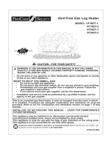
Figure 25 - Correct Burner Flame Pattern
Figure 26 - Incorrect Burner Flame
Pattern
Blue and Bright
Yellow Flames
Darker Orange Flames
AUTO
OFF
ON
Thermopile
Figure 23 - Correct Pilot Flame Pattern
(Your pilot may vary from pilot shown)
Pilot Burner
Thermocouple
Figure 24 - Incorrect Pilot Flame Pattern
(Your pilot may vary from pilot shown)
Pilot Burner
Thermocouple
Check pilot ame pattern and burner ame
patterns often.
PILOT FLAME PATTERN
Figure 23 shows a correct pilot ame pattern.
Figure 24 shows an incorrect pilot ame pat-
tern. The incorrect pilot ame is not touching
the thermocouple. This will cause the thermo-
couple to cool. When the thermocouple cools,
the heater will shut down.
If pilot ame pattern is incorrect, as shown
in Figure 24
• turn heater off (see To Turn Off Gas to Ap-
pliance, page 18)
• see Troubleshooting, page 22
Note: The pilot ame on natural gas units will
have a slight curve, but ame should be blue
and have no yellow or orange color.
If burner ame pattern is incorrect, as shown
in Figure 26
• turn heater off (see To Turn Off Gas to Ap-
pliance, page 18)
• see Troubleshooting, page 22
The ames from the burner travel horizontally
through the log set and emerge at the middle
and rear of the set against the back logs.
The ames are blue off the burner and as
they progress through the log set, change to
a light yellow color, yellow decorative ames
are visible as the ames exit the log set.
The base of the log set and the underside of
the top logs glow red. Natural gas models will
burn with more blue ame, while propane gas
model will burn with bright yellow ame.
Figure 25 shows correct burner ame pattern.
WIRING DIAGRAM
/