Page is loading ...

1
Version 1.1B June 2016
TABLE OF CONTENTS
About Us………………………….….….…1
Product Specifications……………………1
Important Safety Information…………….2
Product Features………………………….4
Installation Checklist……………………...5
Water Vapor……………………………….7
Air for Combustion…………………….….8
Determining Fresh Air Flow……………...9
Installation Considerations…………………11
Connecting to Gas Supply..........................17
Unit Operation……………………………….19
Care and Maintenance…...........................22
Troubleshooting…………...........................23
Illustrated Parts and Parts List...................27
Service Schedule, Registration
and Contact Information............................28
ABOUT US
We at Reecon strive to produce the highest quality Thermablaster heaters to warm our customers. We
feel that a heater should look as good as it operates and work without a fuss. That is why we have
developed our patent pending dual fuel heating system, which allows the use of either liquid propane or
natural gas for some of our most popular products, without requiring any adjustments. Our product lines
consist of vent free gas wall heaters, a direct vent gas wall heater line, kerosene and propane forced air
heaters, electric industrial heaters, fireplace sets, as well as outdoor heating products. Through our
innovative product design and customer first mentality, we strive to provide the best heaters for all needs,
at a price that won’t break the bank.
PRODUCT SPECIFICATIONS
Model
GLDF24M-V
Gas type
Using natural gas
Nominal Heat Input
48,000 Btu/hr
Minimum Inlet Supply Pressure (W.C.)
6”
Maximum Inlet Supply Pressure (W.C.)
9”
Manifold Pressure (W.C.)
5.2”
Nominal Input Pressure (W.C.)
7”
Gas type
Using propane gas
Nominal Heat Input
40,000 Btu/hr
Minimum Inlet Supply Pressure (W.C.)
8”
Maximum Inlet Supply Pressure (W.C.)
14”
Manifold Pressure (W.C.)
6”
Nominal Input Pressure (W.C.)
11”
Ignition
Electric Pulse
Package Dimension (H×W×D)
16.93”x26.57”x17.32”
Heater Dimension (HxWxD)
15.70”x24”x12”

2
IMPORTANT SAFETY INFORMATION
IMPORTANT: Read this owner’s manual
carefully and completely before trying to
assemble, operate, or service this heater.
Improper use of this heater can cause serious
injury or death from burns, fire, explosion,
electrical shock, and carbon monoxide poisoning.
Only a qualified installer, service agent, or local
gas supplier may install and service this product.
WARNING: Do not store or use gasoline
or other flammable vapors and liquids in the
vicinity of this or any other appliance.
CARBON MONOXIDE POISONING: Early signs
of carbon monoxide poisoning resemble the flu
with headache, dizziness and/or nausea. If you
have these signs, heater may not be working
properly. Get fresh air at once! Have heater
serviced. Some people - pregnant women,
persons with heart or lung disease, anemia,
those under the influence of alcohol, those at
high altitude - are more affected by carbon
monoxide than others.
Natural and Propane /LP Gas: Natural and
Propane/LP gas are odorless. An odor-producing
agent is added to the gas. The odor helps you
detect a gas leak. However, the odor added to
the gas can fade. Gas may be present even
though no odor exists.
WARNING: Any change to this heater or its
controls can be dangerous.
WARNING: Do not use any accessories
not approved for use with this heater.
WARNING: Carefully supervise young
children when they are in the room with the
heater.
WARNING: Make sure grill guard is in
place before running heater.
WARNING: Keep the appliance area clear
and free from combustible materials, gasoline,
and other flammable vapors and liquids.
WARNING: Due to high temperatures, the
appliance should be located out of traffic and
away from furniture and draperies.
WARNING: Heater becomes very hot
when running. Keep children and adults away
from hot surfaces to avoid burns or clothing
ignition. Heater will remain hot for a time after
shutoff. Allow surfaces to cool before touching.
WARNING: Do not place clothing or other
flammable material on or near the appliance.
Never place any objects in the heater.
WARNING: Failure to keep the primary air
opening(s) of the burner(s) clean may result in
sooting and property damage.
WARNING: Do not allow fans to blow
directly towards the heater. Avoid any drafts that
alter burner flame patterns.
WARNING: Do not use a blower insert,
heat exchanger insert or other accessory not
approved for use with this heater.
WARNING: Failure to position the parts in
accordance with these diagrams or failure to use
only parts specifically approve with this heater
may result in property damage or personal injury.
CAUTION: Two gas line installations at the same
time are prohibited. The ignition button on the
dual fuel models shall not be depressed while the
heater is in operation.
1. Installation and provisions for combustion and
ventilation air must conform with the National
Fuel Gas Code, ANSI Z223.1/NFPA 54, or the
Natural Gas and Propane Installation Code, CSA
B149.1.
2. Do not place Propane/LP supply tank(s) inside
any structure. Propane/LP supply tank(s) must
be placed outdoors.
3. This heater shall not be installed in the place

3
which the strong wind would shut down the
appliance.
4. This heater needs fresh air ventilation to run
properly. This heater has an Oxygen Depletion
Sensing (ODS) safety shutoff system. The ODS
shuts down the heater if not enough fresh air is
available. See Air for Combustion and Ventilation,
page 7. If heater keeps shutting off, see
troubleshooting.
5. Keep all air openings in front and bottom of
heater clear and free of debris. This will ensure
enough air for proper combustion.
6. If heater shuts off, do not relight until you have
provided fresh air from outside. If heater keeps
shutting off, have it serviced.
7. Do not run heater where flammable liquids or
vapors are used or stored under dusty
conditions.
8. Before using furniture polish, wax, carpet
cleaner, or similar products, turn heater off. If
heated, the vapors from these products may
create a white powder residue within burner box
or on adjacent walls or furniture.
9. Never set control knob between locked
positions, otherwise poor combustion and higher
levels of carbon monoxide may be resulted.
10. “Do not use this appliance if any part has
been under water. Immediately call a qualified
service technician to inspect the room heater and
to replace any part of the control system and any
gas control which has been under water.”
11. Turn off and let heater cool down before
servicing. Only a qualified service person should
service and repair heater.
12. Periodic visual check of pilot and burner
flame, with pictorial sketches or drawings.
13. The appliance must be isolated from the gas
supply piping system by closing its equipment
shut-off valve during any pressure testing of the
gas supply piping system at test pressures equal
to or less than 1/2 psi (3.5 kPa).
14. This appliance must be installed only in a
solid-fuel burning fireplace with a working flue
and constructed of noncombustible material.
15. Solid fuels shall not be
burned
in a fireplace
where a
decorative appliance
is
i
n
stalled.
16. A fireplace screen must be in place when the
appliance is operating and unless other
provisions for combustion air are provided, the
screen shall have an opening(s) for introduction
of combustion air.
17. The installation of
a
pp
li
a
n
c
e
s
d
e
s
i
gn
e
d
for
m
a
n
u
f
a
c
t
u
r
e
d
home
(U.S. only) or
mob
il
e
home
installation must
conform
with the
Standard for Mobile
Hous
i
n
g
,
CAN/CSA Z240
MH, in C
a
nada,
or with the Manufactured Home
Construction and Safety Standard,
Title
24
CFR
,
Part
3280,
in
the
United
States, or when such a
standard
is not
applicable,
Manufactured Home
Installat
i
o
n
s
S
t
an
dar
d
,
ANSI/NCSBCS
A
225
.
1
/N
FP
A
50
1A
.
18. Logs are fragile; handle with care.
19.
A damper clamp must be installed to
provide minimum permanent vent
opening to vent flue products, Refer to
installation instructions
.
Important Note:
An unvented room heater having an input
rating of more than 10,000 Btu/hr (2,931
W) shall not be installed in a bedroom or
bathroom; or
An unvented room heater having an input
rating of more than 6000 Btu/hr (1,758 W)
shall not be installed in a bathroom.
WARNING: This product contains
chemicals including lead and lead compounds,
known to the State of California to ca use birth
defects (or other reproductive harm known to
cause cancer)

4
WARNING: Combustion by-products produced when using this product contains carbon monoxide,
a chemical known to the State of California to ca use birth defects (or other reproductive harm known to
cause cancer)
QUALIFIED INSTALLING AGENCY
Only a qualified agency should install and replace gas piping, gas utilization equipment or accessories,
repair and service the heater. The term “qualified agency” means any individual, firm, corporation, or
company that either in person or through a representative is engaged in and is responsible for:
a) Installing, testing, or replacing gas piping or
b) Connecting, installing, testing, repairing, or servicing equipment; that is experienced in such work;
that is familiar with all precautions required; and that has complied with all the requirement of the
authority having jurisdiction.
PRODUCT FEATURES
SAFETY PILOT
This heater has a pilot with an Oxygen Depletion Sensing (ODS) safety shutoff system. The ODS/pilot
shuts off the heater if there is not enough fresh air.
PULSE IGNITION SYSTEM
This heater is equipped with a battery powered electric pulse igniting system. No AC power supply
required. Battery should be periodically checked and replaced accordingly. Use a “D” size (IEC R20 or
LR20) 1.5 V battery only.
GAS OPTIONS CAPABLE (Dual Fuel Models Only) (Models that start with GLDF)
If you have the dual fuel model, your heater is equipped to operate on either propane or natural gas. The
heater will automatically identify your gas source without any manual changes.
LOCAL CODES
Install and use heater with care. Follow all local codes. In the absence of local codes, use the latest
edition of The National Fuel Gas Code, ANSI Z223.1/ NFPA 54.

5
INSTALLATION CHECKLIST
Share this checklist with your professional installer
Manifold Pressure and Nominal Inlet Pressure for appropriate gas type
o Using Natural Gas:
Minimum Inlet Pressure (W.C): 6”
Manifold Pressure (W.C.): 5.2”
Nominal Input Pressure (W.C.): 7”
o Using Propane Gas:
Minimum Inlet Pressure (W.C): 8”
Manifold Pressure (W.C.): 6”
Nominal Input Pressure (W.C.): 11”
Clearances
o 5” minimum from bottom of heater to Top Surface of Floor
o 16” Minimum from sides to of Heater
o 42” Minimum clearance from top surface of heater and up
Connected to gas supply using a 3/8
th
inch UNF inlet connection to a ½ inch gas pipe
Unit is placed in a room that is a minimum of 1,150 square feet.
D battery installed & AA batteries placed in remote.
Adequate ventilation and fresh-air flow is appropriate for heater location
The Air Shutter is pre-set for Liquid Propane use. If using Natural Gas, see Air Shutter section of
manual.
Unit successfully tested
o Installed by:
Company __________________________________________
Installer __________________________________________
Contact Info ________________________________________
Date ______________________________________________
Note to installer: Ensure that you are referencing the product manual for full details on each of the
installation steps, warnings and considerations. This list is to be used to confirm the steps as you move
through the installation. Please leave this sheet with the user.
*Do not attempt any modifications, repairs or replacements on this unit without first discussing with
Thermablaster Technical Support. Doing so will void the product’s warranty. Professional Installation is
required by all local and National codes.
Unit is not to be used as a central heating system

6
Preparing for Installation
Before beginning assembly or operation of the product, make sure all parts are present. Compare parts
with package contents list and diagram above. If any part is missing or damaged, do not attempt to
assemble, install or operate the product. Contact customer service for replacement parts.
Before installing heater, make sure you have the items listed below:
Figure 1 - Vented Gas log
Control Knob
Igniter Knob

7
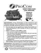
UNPACKING
1. Remove heater from carton.
2. Remove all protective packaging applied to heater for shipping.
3. Check heater for any shipping damage. If heater is damaged, promptly inform dealer where you
purchased heater.
4. Remove thread protective cup on the gas inlet pipe underneath the heater.
5. Install a D size battery. Be sure battery has full capacity. Battery must be removed if the heater is not in
use for an extended period of time.
Figure 2 – Battery Cover
WATER VAPOR: A BY-PRODUCT OF UNVENTED ROOM HEATERS
Water vapor is a by-product of gas combustion. An unvented room heater produces approximately one (1)
ounce (30 ml) of water for every 1,000 BTUs (0.3 KWs) of gas input per hour. Unvented room heaters are
recommended as supplemental heat (a room) rather than a primary heat source (an entire house). In
most supplemental heat applications, the water vapor does not create a problem. In most applications,
the water vapor enhances the low humidity atmosphere experienced during cold weather. The following
steps will help ensure that water vapor does not become a problem:
1. Be sure the heater is sized properly for the application, including ample combustion air and
circulation air.
2. If high humidity is experienced, a dehumidifier may be used to help lower the water vapor content
of the air.
3. Do not use an unvented room heater as the primary heat source.

8
AIR FOR COMBUSTION AND VENTILATION
WARNING: This heater shall not be
installed in a confined space or unusually
tight construction unless provisions are provided
for adequate combustion and ventilation air.
Read the following instructions to ensure proper
fresh air for this and other fuel-burning
appliances in your home.
Providing Adequate Ventilation
This heater shall not be installed in a room or
space unless the required volume of indoor
combustion air is provided by the method
described in the NATIONAL FUEL GAS CODE,
ANSI Z223.1/NFPA 54, the INTERNATIONAL
FUEL GAS CODE, or applicable local codes.
The following are excerpts from National Fuel
Gas Code, ANSI Z223.1/ NFPA 54. Air for
Combustion and Ventilation. All spaces in homes
fall into one of the three following ventilation
classifications:
1. Unusually Tight Construction
2. Unconfined Space
3. Confined Space
The information on the following pages will help
you classify your space and provide adequate
ventilation.
Confined and Unconfined Space
The National Fuel Gas Code, ANSI
Z223 .1/NFPA 54 defines a confined space as a
space whose volume is less than 50 cu. ft. per
1,000 BTU/hr (4.8 m3 per kw) of the aggregate
input rating of all appliances installed in that
space and an unconfined space as a space
whose volume is not less than 50 cubic feet per
1,000 BTU/hr (4.8 m3 per kw) of the aggregate
input rating of all appliances installed in that
space. Rooms connecting directly with the space
in which the appliances are installed, through
openings not furnished with doors, are
considered a part of the unconfined space.
This heater shall not be installed in a confined
space or unusually tight construction unless
provisions are provided for adequate combustion
and ventilation air. Adjoining rooms are
connecting only if there are odorless
passageways or ventilation grills between them.
Unusually Tight Construction
The air that leaks around doors and windows
may provide enough fresh air for combustion and
ventilation. However, in buildings of unusually
tight construction, you must provide additional
fresh air. Unusually tight construction is defined
as construction where:
a) Walls and ceilings exposed to the outside
atmosphere have a continuous water vapor
retarder with a rating of one perm (6×10-11kg
per pa-sec-m2) or less with openings gasket or
sealed and
b) Weather stripping has been added on
openable windows and on doors and
c) Caulking or sealants are applied to areas such
as joints around window and door frames,
between sole plates and floors, between wall
ceiling joints, between wall panels, at
penetrations for plumbing, electrical, and gas
lines, and at other openings.
If your home meets all of the three criteria above,
you must provide additional fresh air. See
“Ventilation Air from Outdoors”. If your home
does not meet all of the three criteria above,
proceed to “Determining Fresh-Air Flow for
Heater Location”.

9
DETERMINING FRESH-AIR FLOW FOR HEATER LOCATION
Use this worksheet to determine if you have a confined or unconfined space. Space: Includes the room in
which you will install heater plus any adjoining rooms with door less passageways or ventilation grills
between the rooms.
1. Determine the Volume of space in cubic feet
Length X Width X Height = ___________________ cu. Ft.
(Including adjoining rooms with door less passageways or ventilation grills between rooms)
Example: 24’ (L) X 16’ (W) 8’ (H) = 3,072 cu. Ft.
2. Multiply the volume of space by 20 BTU/Hr. to determine the maximum BTU/Hr. the space can
support.
Example: 3.072 cu. Ft. X 20 BTU/Hr. = 61,440 BTU/Hr.
(Maximum BTU/Hr. the room can support)
3. Add the BTU/Hr. of all the fuel burning appliances in the space
Vent Free Heater _________________BTU/Hr.
Gas Appliance #1_________________BTU/Hr.
Gas Appliance #2_________________BTU/Hr.
Example: Vent Free Heater 26,000 BTU/Hr.
Gas Appliance #1 35,000 BTU/Hr.
Total 61,000 BTU/Hr.
The space in the prior example is a confined space because the actual BTU/hr used is more than the
maximum BTU/hr the space can support.
You must provide additional fresh air. Your options are as follows:
Rework worksheet, adding the space of an adjoining room. If the extra space provides an unconfined
space:
a) Remove door to adjoining room or add ventilation grills between rooms. See “Ventilation Air
from Inside Building” on next page.
b) Vent room directly to the outdoors. See the following “Ventilation Air from Outdoors” for details.
c) Install a lower BTU/hr heater if lower BTU/hr size makes room unconfined. If the actual BTU/hr
used is less than the maximum BTU/hr the space can support, the space is an unconfined
space. You will need no additional fresh air ventilation.
WARNING: If the area in which the heater may be operated is smaller than that defined as an
unconfined space, or if the building is of unusually tight construction, provide adequate combustion
and ventilation air by one of the methods described in the National Fuel Gas Code, ANSI Z223.1/NFPA
54, Air for Combustion and Ventilation, or applicable local codes.

10
WARNING: If the area in which the heater may be operated does not meet the required volume for
indoor combustion air, combustion and ventilation air shall be provided by one of the methods described
in the National Fuel Gas Code, ANSI Z223.1/NFPA 54, the International Fuel Gas Code, or applicable
local codes.
Ventilation Air from Inside Building
This fresh air would come from an adjoining unconfined space. When ventilating to an adjoining
unconfined space, you must provide two permanent openings: one within 12 inches of the ceiling and one
within 12 inches of the floor on the wall connecting the two spaces (Figure 3). You can also remove the
door into adjoining room (see option 3, Figure 3). Follow the National Fuel Gas Code. ANSI Z223.1/NFPA
54, Air for Combustion and Ventilation for required size of ventilation grills or ducts.
Ventilation Air from Outdoors
Provide extra fresh air by using ventilation grills or ducts. You must provide two permanent openings: one
within 12 inches of the ceiling and one within 12 inches of the floor. Connect these items directly to the
outdoors or spaces open to the outdoors. These spaces include attics and crawl spaces. Follow the
National Fuel Gas Code, ANSI Z223.1/ NFPA 54, Air for Combustion and Ventilation for required size of
ventilation grills or ducts.
IMPORTANT: Do not provide openings for inlet or outlet air into attic if attic has a
thermostat-controlled power vent. Heated air entering the attic will activate the power vent. Rework
worksheet, adding the space of the adjoining unconfined space. The combined spaces must have
enough fresh air to supply all appliances in both spaces.
Figure 3 - Ventilation Air from Inside Building
NOTE: Base not included. Not for use in bedrooms or bathrooms.
Figure 4 - Ventilation Air from Outdoors

11
INSTALLATION CONSIDERATIONS
This heater is intended for use as supplemental heat.
Use this heater along with your primary heating system. Do not install this heater as your primary heat
source. If you have a central heating system, you may run system’s circulating blower while using heater.
This will help circulate the heat throughout the house. In the event of a power outage, you can use this
heater as your primary heat source.
WARNING: A qualified service person must install heater. Follow all local codes.
WARNING: Never install the heater:
in a recreational vehicle
where curtains, furniture, clothing, or other flammable objects are less than 36 inches from the
front, top, or sides of the heater
in high traffic areas
in windy or drafty areas
CAUTION: This heater creates warm air currents. These currents move heat to wall surfaces next
to heater. Installing heater next to vinyl or cloth wall coverings or operating heater where impurities (such
as tobacco smoke, aromatic candles, cleaning fluids, oil or kerosene lamps, etc.) in the air exist, may
cause walls to discolor.
IMPORTANT: Vent-free heaters add moisture to the air. Although this is beneficial, installing
heater in rooms without enough ventilation air may cause mildew to form too much moisture. See Air for
Combustion and Ventilation.
Check Gas Type
Be sure your gas supply is right for your heater. Otherwise, call dealer where you bought the heater from
for proper type heater.
Clearances to Combustibles
Carefully follow the instructions below. This heater is a
freestanding floor seated unit.
WARNING: Maintain the minimum clearances shown
in Figure 5. If you can, provide greater clearances from
floor, ceiling, and joining wall.
Figure 5 – Minimum Clearance to Combustibles

12
If Using Mantel
You must have noncombustible material(s) such as slate, marble, tile,
etc. At least ½ in. thick. With sheet metal you must have
noncombustible material behind it. Noncombustible material must
extend at least 8 inches up. If noncombustible material is less than 12
inches. you must install the fireplace hood accessory. Even if
noncombustible material is more than 12 inches, you may need the
hood accessory to deflect heat away from mantel shelf. See Figure 6, 7
and 8.
Mantel Clearances
In addition to meeting noncombustible material clearances, you must
also meet required clearances between fireplace opening and mantel
shelf. If the clearances listed below are not met, you will need a hood.
Determining Mantel Clearances
If you meet minimum clearances requirements between mantel shelf
and top of fire place opening, a hood is not necessary. See
Figure 6
Determining Minimum Mantel Clearances When Using a
Hood
If minimum clearance is Figure 7 are not met, you must have
a hood. When using a hood there are still certain minimum
clearances required. Follow minimum clearances shown in
Figure 7 when using a hood.
The gas log heater must be installed at least 1 3/8” above
any combustible flooring material, such as carpeting or tile,
which is closer than 14” to the base of the fireplace. The minimum
distance must be maintained from the top surface of carpeting, tile,
etc. See Figure 8.
OR
The gas log heater may be installed nearer to the floor is a
minimum of 14” of noncombustible material such as a slate or
marble is installed between the base of the fire place and the
combustible flooring. See Figure 9.
When installing your log set as a vent free installation the damper
clamp can be used to eliminate the potential for odors when
burning the logs for the first time.
IMPORTANT: If these minimum clearances are not met, you
must operate heater with chimney flue damper open. Go to
“Installing Damper Clamp”, page 13.
Figure 8 – Minimum Clearance Above
Combustible Flooring.
Figure 6 – Heat Resistance material
with No Hood
Figure 7 – Minimum mantel clearances
with No Hood

13
Figure 9 – Minimum Clearance Above
Combustible Flooring with Noncombustible
Material Installed at Base of Fireplace.
Figure 10 - Damper
Installing Damper Clamp
Remove all ashes or other debris from the fireplace. If the fireplace is equipped with an ash dump, be
sure to seal the door with furnace cement or high temperature silicone. Be sure to check the damper for
proper operation and verify that the flue passageway is open.
Place the clamp over the lip of the damper and tighten the hold down bolt until the clamp is securely
attached to the damper. This will prevent the damper from accidentally closing.
Chimney damper must be fixed in a manner which will maintain the minimum permanent vent opening at
all times. (Damper manufacture shall recommend means to accomplish this, such as by a screw or bolt in
the edge of the damper to prevent its closing or by a hole or holes in the damper).
Manual and millivolt controlled gas logs may be installed as a vented decorative log set in compliance
with ANSI Z21.60 and National Fuel Gas Code. When the gas logs are operated with the damper open,
non-combustible material and minimum mantel requirements do not apply.
Note: When installing your log set as a vented installation the damper clamp (Not Provided in hardware)
must be used.
Floor Clearances:
1. If installing appliance on the floor, you must maintain the minimum distance of 14 inches to
combustibles (see Figure 9)
2. If combustible materials are less than 14 inches to the fireplace, you must install appliance at least
5 inches above the combustible flooring (See Figure 8)

14
Air Door
Setting the Air Door to the appropriate gas type being supplied to the log set is important, as it improves
the color and appearance of the flame. The Air Door is located on the bottom of the log set heater. So,
you will need to flip it over. I recommend laying a cloth down so that the metal of the burner does not rub
on the floor. You will want to look for an oval shaped cover that has two screws.
You will unscrew this door, revealing a silver cylinder shaped part that has a single screw. The unit comes
preset for Propane, so at first, the screw will be facing towards LP (Liquid Propane).
Air Door
Loosen this screw

15
Loosen this screw.
Then, with your screwdriver still contacting the screw, slide/rotate the cylinder towards the NG (Natural
Gas) side until it cannot slide any further.
Once done, you will tighten the screw on the cylinder, then seal the air shutter cover again.
For more information please visit our website www.thermablaster.com. You can contact us at
877-670-8428 or via email service@thermablaster.com.
Minimum Firebox Dimensions
Model
A- Front Width
B- Length
C- Rear Width
D- Height
GLDF24M-VF
28”
16”
26”
24”

16
Log Placement
Ensure that your heater’s logs are placed as shown below. It’s important that your logs do not cover
burner holes, as this can lead to sooting and an overall drop in the performance of your heater. Logs
should be placed sequentially, from lowest to highest, as the numbering indicates. There are grooves on
many of the logs that allow for simple placement and help to prevent the logs from shifting positions.
6
4
5
7
3
2
3
5
1

17
FIREPLACE PREPARATION
FOR FACTORY BUILT FIREPLACES
Free
Opening Area
of
Chimney Damper
For
Venting Combustion Products From
Decorative Appliances
For
Installation
In Solid-Fuel Burning Fireplaces
Appliance Input Rate
(kBTU/hr)
30
40
50
Chimn
e
y
Height* (ft)
Minimum Opening** (sq. in.)
10
16.6
22.1
28.3
15
12.6
17.3
21.2
20
10.8
14.5
18.1
25
9.6
12.6
15.9
30
9.1
11.3
14.5
35
8.0
10.8
13.2
40
7.5
10.2
12.6
* Height is from
hearth
to top of
chimney
and the
min
i
mum
height
is 10 feet.
** Chart shows
min
i
mum
opening
(sq. in.) for the given
height
and input rate
.
FOR MASONRY BUILT FIREPLACES
Free
Opening Area
Of
Chimney Damper
For V
enting Combustion Products
From Decorative Appliances
For
Installation
In Solid-Fuel Burning
Fireplaces
Appliance Input Rate
(kBTU/hr)
30
40
50
Chimn
e
y
Height* (ft)
Minimum Opening** (sq. in.)
6
25.7
33.8
41.7
8
23.7
31.2
38.7
10
21.7
28.7
35.2
15
19.9
26.1
32.0
20
18.5
23.7
28.8
30
16.9
21.6
26.5
* Height is from
hearth
to top of
chimney
and the
minimum height
is 6 feet.
** Chart shows
min
i
mum
opening
(sq. in.) for a given
height
and input
rate.

18
CONNECTING TO GAS SUPPLY
WARNING: A qualified service technician must connect heater
to gas supply. Follow the heater specification and all local
codes. Wrong gas supply may result improper operation, or damage
on your heater, property or/and personal body.
WARNING: This appliance requires a 3/8-inch UNF (Unified
National Fine) inlet connection to the pressure regulator.
WARNING: Never connect heater to private (non-utility) gas
wells. This gas is commonly known as wellhead gas.
WARNING: Do not over-tighten gas connections.
CAUTION: Use only new, black iron or steel pipe. Internally tinned copper tubing may be used in
certain areas. Check your local codes. Use pipe of 1/2-in. diameter or greater to allow proper gas
volume to heater. If pipe is too small, undue loss of pressure will occur.
NATURAL GAS MODELS:
CAUTION: Check your gas line pressure before connecting heater to gas line. Gas line pressure
must be no greater than 8 inches of water column. If gas line pressure is higher, damage on
appliance regulator could occur.
PROPANE MODELS:
CAUTION: Never connect heater directly to the gas supply. This heater requires an external
regulator (not supplied). Install the external regulator between the heater and gas supply.
CAUTION: Avoid damage to regulator. Hold gas regulator with wrench when connecting into gas
piping and/or fittings.
CAUTION: Use pipe joint sealant that is resistant to gas (Propane or Natural Gas).
IMPORTANT: Install an equipment shutoff valve in an accessible location where the gas pipe goes
indoors. The equipment shutoff valve is for turning on or shutting off the gas to the appliance. Apply pipe
joint sealant lightly to male threads. This will prevent excess sealant from going into pipe. Excess sealant
in pipe could result in clogged heater valves. The installer must supply an external regulator with nominal
outlet pressure of 11” water column and sufficient flow rates. Install external regulator with the vent
pointing down as shown in Figure 11. Pointing the vent down protects it from freezing rain or sleet. If
flexible gas hose is applied, it should meet the requirements of ANSI/UL569 Standard for Pigtail and
Flexible Hose Connection for LP-Gas. Improper regulator and/or gas hose assembly may occur damage
on your heater, property or/and personal body.
Propane/LP
supply tank
External regulator
Figure 11 - External Regulator with Vent Pointing Down

19
CAUTION: Two gas lines installation at the same time is forbidden. Do not the open cover while
the heater is running.
CAUTION: To avoid gas leakage at the inlet of appliance regulator, a qualified installer or service
technician must use steel or metal hex plug with sealant.
Changing from Liquid Propane to Natural Gas supply:
1) Your heater is equipped with a unique automatic gas source detection and configuration system,
allowing it to perform using both liquid propane and natural gas without any manual conversion.
2) Only a qualified installer or service technician can perform gas type conversion from between
liquid propane and natural gas supply. This is due to the type of connection and installation
required external the heater.
CHECKING GAS CONNECTIONS
WARNING: Test all gas piping and connections for leaks after installing or servicing. Correct all
leaks at once.
WARNING: Never use an open flame to check for a leak. Apply a mixture of liquid soap and water
to all joints. If bubbles form, there is a leak. Correct all leaks at once.
Pressure Testing Gas Supply Piping System
Test Pressures in Excess of 1/2 PSIG (3.5kPa)
1. Disconnect heater with its appliance main gas valve (control valve) and equipment shutoff valve from
gas supply piping system. Pressures in excess of 1/2 PSIG will damage heater regulator.
2. Cap off open end of gas pipe where equipment shutoff valve was connected.
3. Pressurize supply piping system by either using compressed air or opening gas supply valve.
4. Check all joints of gas supply piping system. Apply mixture of liquid soap and water to gas joints. If
bubbles form, there may be a leak.
5. Correct all leaks at once.
6. Reconnect heater and equipment shutoff valve to gas supply. Check reconnected fittings for leaks.
Test Pressures Equal to or Less Than 1/2 PSIG (3.5 kPa)
1. Close equipment shutoff valve
2. Pressurize supply piping system by either using compressed air or opening natural supply tank valve.
3. Check all joints from gas meter to equipment shutoff valve. Apply mixture of liquid soap and water to
gas joints. If bubbles form, there is a leak.
4. Correct all leaks at once.
Pressure Testing Heater Gas Connections
1. Open equipment shutoff valve.
2. Open gas supply tank valve.
3. Make sure control knob of heater is in the OFF position.
4. Check all joints from equipment shutoff valve to control valve. Apply mixture of liquid soap and water to
gas joints. If bubbles form, there may be a leak.
5. Correct all leaks at once.

20
UNIT OPERATION
FOR YOUR SAFETY READ BEFORE LIGHTING
WARNING: If you do not follow these instructions exactly, a fire or explosion may result causing
property damage, personal injury or loss of life.
1. When lighting the pilot, follow these instructions exactly.
2. BEFORE LIGHTING, smell all around the appliance area for gas. Be sure to smell next to the floor
because some gas is heavier than air and will settle on the floor.
3. Use only your hand to push in or turn the gas control knob. Never use tools. If the knob will not push in
or turn by hand, don’t try to repair it, call a qualified service technician or gas supplier. Forced or
attempted repair may result in a fire or explosion.
4. Do not use this appliance if any part has been under water. Immediately call a qualified service
technician to inspect the appliance and to replace any part of the control system and any gas control
which has been under water.
WHAT TO DO IF YOU SMELL GAS
Open the window or door immediately.
Do not try to light any appliance.
Do not touch any electric switch, do not use any phone in your building.
Immediately call your gas supplier from a neighbor’s phone. Follow the gas supplier’s instructions.
If you cannot reach your gas supplier, call the fire department.
LIGHTING INSTRUCTIONS
Before Lighting:
1. Make sure the heater is properly installed and connected. Open the external safety shut off valve (not
part of the heater) on gas inlet line to the heater.
2. Wait five (5) minutes to clear out air inside gas lines. Smell if there is any leakage.
IMPORTANT: If you smell any gas, do not try to light any appliances, do not touch electrical
switches or use any phone in the building. Shut off the valve on gas inlet line immediately and
contact gas supplier from a neighbor’s phone. Follow gas supplier’s instructions. If you can’t
reach the gas supplier, call the fire department. Only when you make sure there is no gas leakage,
go to the next step.
Note: During first seasonal use, gas smell is expected to be more noticeable than in standard operation.
/