Dometic Passport I/O Digital Control Operating instructions
- Category
- Split-system air conditioners
- Type
- Operating instructions
This manual is also suitable for

COPYRIGHT © 2007-2017 Dometic Corporation. All Rights Reserved.
No part of this publication may be reproduced, translated, stored in a retrieval system, or transmitted in any form or by any means
electronic, mechanical, photocopying, recording or otherwise without prior written consent by Dometic Corporation. Every precaution
has been taken in the preparation of this manual to ensure its accuracy. However, Dometic Corporation assumes no responsibility for
errors and omission. Neither is any liability assumed for damages resulting from the use of this product and information contained
herein.
Passport I/O Digital Control
(for Direct Expansion Systems)
OPERATIONS MANUAL
Passport I/O Compact
Passport I/O (legacy model)
Dometic Corporation
Rev. 20170816
L-2231 English
Part Number: 297200023

L-2231 ENGLISH
Table of Contents
INTRODUCTION . . . . . . . . . . . . . . . . . . . . . . . . . . . . . . . 1
R
EAD THIS MANUAL BEFORE PROCEEDING . . . . . . . . . 1
FEATURES . . . . . . . . . . . . . . . . . . . . . . . . . . . . . . . . . 1
Standard . . . . . . . . . . . . . . . . . . . . . . . . . . . . . . 1
Optional . . . . . . . . . . . . . . . . . . . . . . . . . . . . . . 1
D
ESCRIPTION OF CONTROL . . . . . . . . . . . . . . . . . . . . 1
Power . . . . . . . . . . . . . . . . . . . . . . . . . . . . . . . . 1
Set Point . . . . . . . . . . . . . . . . . . . . . . . . . . . . . . 1
Fan . . . . . . . . . . . . . . . . . . . . . . . . . . . . . . . . . . 1
Memory . . . . . . . . . . . . . . . . . . . . . . . . . . . . . . . 1
I
MPORTANT PROGRAMMING NOTES TO INSTALLER AND
E
ND USER . . . . . . . . . . . . . . . . . . . . . . . . . . . . . . . . . 3
N
ORMAL HEATING OR COOLING CYCLE . . . . . . . . . . . . 3
R
EVERSING VALVE OPERATION . . . . . . . . . . . . . . . . . 3
INSTALLING THE DISPLAY PANEL . . . . . . . . . . . . . . . 3
C
HOOSING THE LOCATION . . . . . . . . . . . . . . . . . . . . . 3
M
OUNTING THE DISPLAY . . . . . . . . . . . . . . . . . . . . . . 4
MOUNTING THE OPTIONAL SENSORS . . . . . . . . . . . . . 4
Remote Air Sensor . . . . . . . . . . . . . . . . . . . . . . 4
Outside Air Temperature Sensor . . . . . . . . . . . 4
Service Sensor . . . . . . . . . . . . . . . . . . . . . . . . . 4
OPERATION . . . . . . . . . . . . . . . . . . . . . . . . . . . . . . . . . . 4
O
PERATOR CONTROLS AND DISPLAY PANEL . . . . . . . . 4
Display Indicators . . . . . . . . . . . . . . . . . . . . . . . 4
Button Functions - Single . . . . . . . . . . . . . . . . . 5
Button Functions - Dual . . . . . . . . . . . . . . . . . . 5
Special Button Functions . . . . . . . . . . . . . . . . . 5
M
ODES OF OPERATION . . . . . . . . . . . . . . . . . . . . . . . 5
Off Mode . . . . . . . . . . . . . . . . . . . . . . . . . . . . . . 5
On Mode . . . . . . . . . . . . . . . . . . . . . . . . . . . . . . 5
Automatic Mode . . . . . . . . . . . . . . . . . . . . . . . . 5
Cool Mode . . . . . . . . . . . . . . . . . . . . . . . . . . . . 6
Heat Mode . . . . . . . . . . . . . . . . . . . . . . . . . . . . 6
Moisture Mode . . . . . . . . . . . . . . . . . . . . . . . . . 6
Fan Modes . . . . . . . . . . . . . . . . . . . . . . . . . . . . 6
Program Mode . . . . . . . . . . . . . . . . . . . . . . . . . 6
U
SING PROGRAM MODE . . . . . . . . . . . . . . . . . . . . . . . 6
Entering Program Mode . . . . . . . . . . . . . . . . . . 6
Exiting Program Mode . . . . . . . . . . . . . . . . . . . 6
Changing Parameters . . . . . . . . . . . . . . . . . . . . 7
Memorizing New Program Parameters . . . . . . . 7
Restoring Memorized Default Settings . . . . . . . 7
Software Identification . . . . . . . . . . . . . . . . . . . 7
P
ROGRAMMING . . . . . . . . . . . . . . . . . . . . . . . . . . . . . . 7
Programming procedure . . . . . . . . . . . . . . . . . . 7
Programmable Parameters . . . . . . . . . . . . . . . . 7
F
AILSAFE AND FAULT-HANDLING CODES . . . . . . . . . . 11
Failsafe Level 0 . . . . . . . . . . . . . . . . . . . . . . . . 11
Failsafe Level 1 . . . . . . . . . . . . . . . . . . . . . . . . 11
Failsafe Level 2 . . . . . . . . . . . . . . . . . . . . . . . . 12
Failsafe Level 3 . . . . . . . . . . . . . . . . . . . . . . . . 12
Q
UICK-START OPERATIONS CHECKLIST . . . . . . . . . . . 12
TROUBLESHOOTING . . . . . . . . . . . . . . . . . . . . . . . . . 12
GENERAL TROUBLESHOOTING . . . . . . . . . . . . . . . . . . 12
DIGITAL-CONTROLS TROUBLESHOOTING . . . . . . . . . . 14
MAINTENANCE . . . . . . . . . . . . . . . . . . . . . . . . . . . . . . 15
SYSTEM COMPONENTS . . . . . . . . . . . . . . . . . . . . . . . 15
Reversing Valve . . . . . . . . . . . . . . . . . . . . . . . 15
Seawater Strainer . . . . . . . . . . . . . . . . . . . . . . 15
Condenser Coil . . . . . . . . . . . . . . . . . . . . . . . . 15
Return-Air Filter . . . . . . . . . . . . . . . . . . . . . . . . 16
Winterization . . . . . . . . . . . . . . . . . . . . . . . . . . 16
A
UTOMATED FACTORY SELF-TEST PROGRAM . . . . . . 16
S
ERVICE UTILITIES . . . . . . . . . . . . . . . . . . . . . . . . . . 17
Hour Meter . . . . . . . . . . . . . . . . . . . . . . . . . . . 17
Service History Log . . . . . . . . . . . . . . . . . . . . . 17
SPECIFICATIONS . . . . . . . . . . . . . . . . . . . . . . . . . . . . . 18
O
PERATIONAL . . . . . . . . . . . . . . . . . . . . . . . . . . . . . . 18
D
IMENSIONS . . . . . . . . . . . . . . . . . . . . . . . . . . . . . . . 18
CABLE LENGTHS . . . . . . . . . . . . . . . . . . . . . . . . . . . . 18
S
YSTEM INPUTS . . . . . . . . . . . . . . . . . . . . . . . . . . . . 18
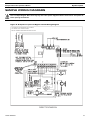
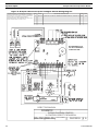
SAMPLE WIRING DIAGRAMS . . . . . . . . . . . . . . . . . . . 19

Passport I/O Control Operations Manual Read This Manual Before Proceeding
L-2231 ENGLISH 1
INTRODUCTION
The Passport I/O is a microcontroller-based unit designed for use with direct expansion, reverse-cycle air conditioning systems.
READ THIS MANUAL BEFORE PROCEEDING
Read this manual completely before you proceed with the installation and operation of the Passport I/O. If you have questions or
require assistance with your Passport I/O, call your dealer or the Dometic Marine Service Department at +1 954-973-2477.
The Passport I/O is covered under the Owner’s Limited Warranty Policy. Incorrect installation, neglect and system abuse are not
covered under the Owner’s Limited Warranty Policy.
FEATURES
STANDARD
OPTIONAL
• Outside air-temperature sensor.
• Alternate air-temperature sensor.
• Pump Sentry water sensor.
• Electric heating control capabilities.
• Air Filter Cleaning or Replacement Timer (available in software revision A21 or newer).
• Low-Voltage Monitor (available in software revision A21 or newer).
This manual provides all necessary information for proper installation and operation of the Passport I/O. Poor installation or
misunderstood operating parameters will result in unsatisfactory performance and possible failure.
DESCRIPTION OF CONTROL
See Figure 1 and Table 1 on page 2 to identify all parts of the control.
POWER
Press the Power button once to engage the system. The display is blank when the system is off and indicates current room
temperature when the system is on.
SET POINT
Press the Up or Down button to set the desired room temperature. To view the set point, momentarily press and release the Up
or Down button.
FAN
Fan-speed operation is automatic, allowing fan speed to decrease as set-point temperature is approached in the Cool Mode.
The fan operates at low speed when set point is satisfied.
Normally the automatic fan speed operation is reversed in the Heating Mode, however, you can program the fan to operate the
same as in the Cooling Mode.
Press the Fan button to select manual fan speeds if you want to override automatic operation. You can program the fan to run
only during a cool or heat cycle, otherwise the fan runs constantly.
MEMORY
The Passport I/O has nonvolatile memory requiring no batteries or backup power. When power is lost, the operating parameters
are retained indefinitely. When power is restored, the control resumes operating as last programmed.
• Universal 115/230 volt, 50/60 Hz AC power supply.
• User-friendly four-button display panel.
• 5V microcontroller located in the display.
• Option to display temperature in degrees F or C.
• Ambient air sensor in face plate.
• Programmable fail-safe modes.
• Programmable parameters.
• Nonvolatile memory requires no backup power.
• Switch inputs for High/Low Refrigerant pressure.
• Humidity Mode control.
• De-icing cycle prevents evaporator icing.
• Programmable fan operation.
• Programmable compressor delays.
• Programmable display brightness.

Description of Control Passport I/O Control Operations Manual
2 L-2231 ENGLISH
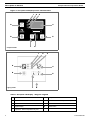
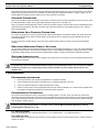
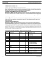
Figure 1: Passport I/O Display Panel and Indicators
Table 1: Passport I/O Display - Diagram Legend
1
Cool Mode indicator
6
Temperature sensor
2
Fan indicator
7
Down button - Lower temperature set point
3
Heat Mode indicator
8
Fan button
4
Digital display
9
Power button
5
Up button - Raise temperature set point
4
123
7
6
5
8
9
Legacy model
123
4
5
67
8
9
Compact model

Passport I/O Control Operations Manual Important Programming Notes To Installer and End User
L-2231 ENGLISH 3
IMPORTANT PROGRAMMING NOTES TO INSTALLER AND END USER
1. If your air conditioning unit is Cool Only (if it does not have a reversing valve), then you MUST program Cool Only
Mode into parameter P-1 (factory default is Automatic Mode). DO NOT program Automatic Mode for a Cool Only unit.
If Automatic Mode is selected and the thermostat calls for heat, the compressor will run. Since there is no reversing
valve, the air conditioning unit will supply cool air when heating is desired. Cool Only units do not heat. See “P-1:
Operating Mode” on page 7 for more information on how to set the proper operating mode.
2. If your air conditioning unit has a Shaded-Pole (SP) fan motor instead of a Split-Capacitor (SC) High-Velocity (HV) fan
motor, you MUST program “SP” into parameter P-16 before operating the equipment. The SP units are recognizable
by an overhanging blower motor. (The SC motor of an HV unit is inside the blower, and the unit has “VTD” or “HV” in
the model number.) Only reprogram this parameter if you do NOT have an HV blower.
3. When powering on the control, press and immediately release the Power button so you do not unintentionally enter
Program Mode. You will enter Program Mode if the Power button is pressed and held for more than 5 seconds. If you
enter Program Mode unintentionally, any subsequent presses of the Up or Down buttons will change the P-1
parameter setting since it is the first parameter shown after entering this mode. This will change the operating mode to
Cool Only, Heat Only, or Automatic, which could result in improper system operation. Always use care when in
Program Mode. For further information, refer to “Using Program Mode” on page 6.
NORMAL HEATING OR COOLING CYCLE
In Automatic Mode, heating and cooling are supplied as required. If cooling is required, the system will start a cooling cycle
when the cabin temperature exceeds the set point by 2°F (1.1°C) and will continue to cool until the temperature equals the set
point. The cabin temperature must drop below the set point by at least 4°F (2.2°C) in order for the system to switch from cooling
to heating. Similarly, if heating is required, the system will start a heating cycle when the cabin temperature is below the set
point by 2°F (1.1°C) and will continue to heat until the temperature equals the set point. The cabin temperature must exceed the
set point by at least 4°F (2.2°C) in order for the system to switch from heating to cooling.
If you select Cool Mode, only cooling is supplied. If you select Heat Mode, only heating is supplied. The cabin temperature in
either mode is maintained within 2°F (1.1°C) of set point by default. When the heating or cooling set point is satisfied, the
compressor cycles off and the fan returns to low speed. The fan speed remains constant if Manual Fan Speed is selected.
For more programming information on this feature, see “P-1: Operating Mode” on page 7.
REVERSING VALVE OPERATION
The position of the reversing valve determines if the system is in Cool Mode or Heat Mode.
In addition, the reversing valve is programmed to toggle in these situations:
• When the system is running and heating or cooling is required, the reversing valve toggles to the opposite mode to
reduce the starting surge of the compressor.
• When a cooling or heating cycle is called for and if the system has been off for less than 75 seconds.
• When a cycle is interrupted from the display panel by pressing the Power button or changing the set point.
Unnecessary valve toggling is limited to reduce reversing-valve noise. You can totally eliminate valve toggling by programming
the minimum compressor staging delay to 75 seconds or greater (see “P-4: Compressor Staging Time Delay” on page 8 for
more information).
Power-On Reset, which occurs when the system is powered up, always initiates a valve toggle.
INSTALLING THE DISPLAY PANEL
CHOOSING THE LOCATION
Before mounting the control panel, consider the location. The display panel’s built-in air sensor provides excellent room-air
temperature sensing when properly located and installed. For air sensor location see item 6 in Figure 1, page 2.
Mount the display panel on an inside wall, slightly higher than mid-height of the cabin, in a location with freely circulating air
where it can best sense average temperature. Its distance from the air conditioner must be within the 15’ (4.5m) length of the
display cable (custom lengths available).
Do not mount the display in direct sunlight, near any heat-producing appliances or in a bulkhead where temperatures radiating
from behind the panel may affect performance. Do not mount the display in the supply-air stream. Do not mount the display

Mounting the Display Passport I/O Control Operations Manual
4 L-2231 ENGLISH
above or below a supply-air or return-air grille. Do not mount the display behind a door, in a corner, under a stairwell or any
place where there is no freely circulating air.
If you can not mount the display in a suitable location for accurately sensing room temperature, install the optional remote air
sensor.
MOUNTING THE DISPLAY
1. Make the cut-out for the display panel.
• For Compact - Cut-out size is 2.5" (63mm) wide by 1.875" (48mm) high.
• For legacy model - Cut-out size is 3.375" (86mm) wide by 2.875" (73mm) high.
2. Plug one end of the display cable (8-pin connector) into the upper-right socket on the circuit board in the electric box
and the other end into the back of the display panel.
3. Clean the mounting surface with isopropyl alcohol only (test alcohol on hidden portion of surface first), then secure
the display panel to a bulkhead with the adhesive strips provided. If the adhesive strips cannot be used directly on the
bulkhead, use the plastic bulkhead adapter. The bulkhead adapter (sold separately) mounts to the bulkhead with
screws and the display panel is secured to the adapter with adhesive strips. Do not use a screw gun and do not over-
tighten screws when mounting adapter.
MOUNTING THE OPTIONAL SENSORS
REMOTE AIR SENSOR
Install the optional remote air sensor if the display can not be mounted in a proper location for accurately sensing room
temperature. Installing the remote air sensor overrides the display’s built-in sensor. The standard cable length for the remote air
sensor is 7 feet (2.1m).
1. Mount the remote air sensor in the return-air stream behind the opening of the return-air grille.
2. Plug its cable (6-pin connector) into the “INSIDE” jack #J3 in the upper-left corner of the circuit board.
OUTSIDE AIR TEMPERATURE SENSOR
Install the optional outside air temperature sensor to monitor the temperature outside the cabin. Outside air sensor cables are
available in various lengths.
1. Mount the sensor outside but not in direct sunlight.
2. Plug its cable into the 2-pin white jack #P3.
SERVICE SENSOR
Install the optional condenser coil temperature sensor into the “H2O OUT” 2-pin blue jack. Use of this sensor must be enabled
via program parameter P-9, the Pump Sentry feature. See “P-9: Optional Pump Sentry” on page 9 for details.
OPERATION
OPERATOR CONTROLS AND DISPLAY PANEL
Refer to Figure 1, page 2 for the button locations and display functions listed below.
DISPLAY INDICATORS
• Cool Mode Indicator - The Cool Mode LED lights when the cool-only mode is selected or when the unit is in an
Automatic Mode cooling cycle.
• Fan Indicator - The Fan Indicator LED lights when a manual fan speed is selected.
• Heat Mode Indicator - The Heat Mode LED lights when the heat-only mode is selected or when the unit is in an
Automatic Mode heating cycle.
• Digital Display - The 3-digit, 7-segment digital display shows inside air temperature when the control is on. It displays
the set point when either the Up or Down button is pressed. The display also indicates program information and fault
NOTE
Do not staple any sensor cables when mounting.

Passport I/O Control Operations Manual Modes of Operation
L-2231 ENGLISH 5
codes. When the control resumes operation after a power interruption, "888" appears in the display and all the LEDs
light for one second. This is normal Power-On Reset operation.
BUTTON FUNCTIONS - SINGLE
• Power button - Press and release to toggle between the On and Off Modes.
• Up button - Press and release to display the set point. Press and hold the Up button to increase the set point. Set
point increases one degree each time the button is pressed.
• Down button - Press and release to display the set point. Press and hold the Down button to decrease the set point.
Set point decreases one degree each time the button is pressed.
• Fan button - Press to advance through the available fan settings. One through six indicates Manual Fan Speeds. One
is the lowest fan speed and six is the highest fan speed. The letter “A” displays when automatic fan operation is
selected.
BUTTON FUNCTIONS - DUAL
• Up & Down buttons (On Mode) - Simultaneously press the Up and Down buttons while in the On Mode to display
outside air temperature (if the optional outside air temperature sensor is installed).
• Up & Down buttons (Program Mode) - Simultaneously press the Up and Down buttons while in the Program Mode to
set new program defaults.
• Power & Down buttons (On Mode) - Simultaneously press the Power and Down buttons while in the On Mode to
enter the Moisture Mode.
• Power & Down buttons (Fault History) - Simultaneously press the Power and Down buttons while viewing the
service fault history log to clear the fault history log.
• Power & Up buttons (On Mode) - Simultaneously press the Power and Up buttons to view the service sensor
temperature (P-9 must be turned on).
• Fan & Down buttons (On Mode) - Simultaneously press the Fan and Down buttons to blank the display.
SPECIAL BUTTON FUNCTIONS
To implement these special functions, disconnect AC power, then press and hold the specified button while reconnecting AC
power.
• Service-History Log - With power to the unit disconnected, press and hold the Fan button while reconnecting the AC
power to view the service history log. Press the Power button once to exit the service history log. See “Service History
Log” on page 17 for details.
• Self-Test Mode - With power to the unit disconnected, press and hold the Power button while reconnecting the AC
power to enter the Self Test Mode. Use the self test to diagnose problems and test the air conditioning system. See
“Automated Factory Self-Test Program” on page 16 for details.
• View Hour Meter - With power to the unit disconnected, press and hold the Down button while reconnecting the AC
power to view the compressor hour meter. Maximum recordable time is 65,536 hours. See “Hour Meter” on page 17 for
details.
MODES OF OPERATION
OFF MODE
When the control is in Off Mode, all control outputs are turned off. Program parameters and user settings are saved in
nonvolatile memory. The Program Mode can only be accessed from the Off Mode.
ON MODE
When the control is in On Mode, power is supplied to the appropriate outputs and the display indicates the current state of
operation. The operating and program parameters resume based on those last stored when the unit was operating.
AUTOMATIC MODE
When Automatic Mode is selected, the system provides both heating and cooling as required. The Heat LED or Cool LED lights
indicate the mode in use. Cabin temperature in a given mode is maintained within 2°F (1.1°C) of set point. If the system was
most recently cooling, the cabin temperature must drop below the set point by at least 4°F (2.2°C) in order for the system to
switch from cooling to heating. Similarly, if the system was most recently heating, the cabin temperature must exceed the set
point by at least 4°F (2.2°C) in order for the system to switch from heating to cooling. This behavior prevents small temperature
overshoots from causing the system to switch between heating and cooling when it is not necessary. To make the temperature
differential between cooling and heating larger, see See “P-23: Auto Mode Heat Differential” on page 10.

Using Program Mode Passport I/O Control Operations Manual
6 L-2231 ENGLISH
COOL MODE
When Cool Mode is selected, the Cool LED is lit and the cooling system operates as required. If the ambient temperature drops
below the set point, the system will not automatically switch to the Heat Mode.
HEAT MODE
When Heat Mode is selected, the Heat LED is lit and the heating system operates as required. If the ambient temperature rises
above the set point, the system will not automatically switch to the Cool Mode.
MOISTURE MODE
Use Moisture Mode to help control humidity. While in the On Mode, simultaneously press the Power and Down buttons. The first
cycle starts in one minute. Every four hours, the fan circulates air for 30 minutes. During this time, the air temperature is
sampled and entered into memory. If necessary, the cooling cycle starts and continues until the temperature is lowered 2°F
(1.1°C) or until the compressor runs a maximum of one hour. Four hours after the temperature is satisfied or the compressor
times out, the cycle repeats. The “HU1” code displays while in Moisture Mode. Press the Power button once to end Moisture
Mode.
FAN MODES
Automatic Fan Mode
The control has six automatic fan speeds available: The fastest fan speed is “6”, the slowest is “1”. Automatic Fan Mode allows
the control to determine the required fan speed based on temperature differential. This permits a balance between the most
efficient temperature control and slower, quieter fan speeds. To select Automatic Fan Mode, press and release the Fan button
until the letter “A” displays.
Manual Fan Mode
There are six manual fan speeds available: The fastest fan speed is “6”, the slowest is “1”. Manual Fan Mode allows you to
select and maintain a desired fan speed. When a manual fan speed has been selected, the Fan LED lights. The speed level is
momentarily displayed when it is selected. Press and release the Fan button until the desired fan speed number is displayed.
Fan-Only Mode
Use the Fan-Only Mode to operate the fan for air circulation when no cooling or heating is desired. From the Off Mode press
and release the Fan button to start fan speed 1. Press and release again to increment through the other speeds. After reaching
speed level 6, press and release the Fan button to turn off the fan. Turning on the control will revert the fan to the Automatic
Mode or the last selected manual fan setting.
Cycled or Continuous Fan Operation
The fan can be set to run continuously whenever the system is turned on, or it can be set to cycle on and off with the normal
heating and cooling cycles. To change this fan operational setting, select either “CYC” or “con” in P-14. When “CYC” is selected,
the setting has been changed to cycled. When “con” is selected, the setting has been changed to continuous.
PROGRAM MODE
Use Program Mode to adjust operating parameters for your particular needs. Program Mode is also used to fine-tune the
system for the most efficient operation within an installation. (Variables such as ducting, sensor location, and system layout
affect system operation.) The control has factory default settings stored in permanent memory that can be recalled. However,
reprogrammed settings can be saved as the new default, thus overwriting the factory defaults. See “P-17: Reset Memorized
Defaults” on page 9 for details.
USING PROGRAM MODE
ENTERING PROGRAM MODE
You can only enter Program Mode from the Off Mode. If necessary, press the Power button to enter Off Mode. Press and hold
the Power button while in the Off Mode until the letter “P” appears in the display. The characters “P1” followed by the P-1
parameter setting appear in the display. The control is now in the Program Mode. If no programming is attempted for one
minute, the control exits Program Mode and returns to Off Mode.
EXITING PROGRAM MODE
Press the Power button once to exit Program Mode and return to Off Mode. Or, do not attempt any programming for 50
seconds, then the control exits Program Mode and returns to Off Mode. Any programming changes made while in Program
IMPORTANT
When used with optional electric heat, the fan remains on for four minutes after the heater cycles off even if fan is set
to cycled operation.

Passport I/O Control Operations Manual Programming
L-2231 ENGLISH 7
Mode will be saved and put into operation after exiting Program Mode and returning the control to the On Mode. (If you want the
programming changes to become the new defaults, see “Memorizing New Program Parameters” on page 7.) When you exit
Program Mode the software version number (such as “A24”) appears in the display.
CHANGING PARAMETERS
While in Program Mode, press and release the Fan button to increment from one program parameter to the next until you reach
the desired parameter number. The programmable parameters range from P-1 through P-22.
When you reach the desired parameter number, use the Up and Down buttons to select the data or set the desired limits for the
parameter being programmed. See Table 2 on page 10 for a list of the parameters, the possible settings for each, and their
factory default settings.
MEMORIZING NEW PROGRAM PARAMETERS
If you want new parameters to be the program defaults, adjust the parameters to the desired settings, then press the Up and
Down buttons simultaneously while in Program Mode. This memorizes the new settings as program defaults and exits the
Programming Mode.
To return to the factory default settings, refer to the factory defaults listed in Table 2 on page 10 and reset the parameters
manually.
RESTORING MEMORIZED DEFAULT SETTINGS
You can restore the last memorized default settings by entering Program Mode and setting P-17 to “rSt”. The memorized default
settings are restored and the control returns to Off Mode. See “P-17: Reset Memorized Defaults” on page 9 for details. To return
to the factory default settings, refer to the factory defaults listed in Table 2 on page 10 and reset the parameters manually.
SOFTWARE IDENTIFICATION
The control’s software version (such as “A24”) appears in the display for one second prior to exit from Program Mode, then the
control returns to Off Mode.
PROGRAMMING
PROGRAMMING PROCEDURE
1. Enter Program Mode. (See “Entering Program Mode” on page 6 for details.)
2. Press and release the Fan button to increment from one program parameter to the next.
3. Use the Up and Down buttons to change the parameter’s setting.
4. Press the Power button to exit Program Mode and return the control to Off Mode. Or, to memorize the changes as the
new defaults, simultaneously press the Up and Down buttons (optional).
PROGRAMMABLE PARAMETERS
The system’s default parameters may be changed by the installing dealer or end user. Once new values are entered and
memorized, the factory defaults are overwritten and the new parameters become the default values. You can restore the original
factory default parameters manually. A summary of the parameters, the permitted values, and original factory default settings of
each are listed in Table 2, page 10.
P-1: Operating Mode
Select an operating mode: For Automatic Mode select “0”, for Cool Mode select “1”, for Heat Mode select “2”.
P-2: High Fan Limit
Values for the upper fan-speed limit range from 65 to 95. Set a higher number to increase the fan speed or a lower number to
slow the fan speed.
NOTE
If you have any reason to contact Dometic about the system or programming the control, you must have the software
identification number and air conditioning unit serial number available. The serial number may be found on the
dataplate label.
IMPORTANT
If you have any programming problems or confusion occurs, reset the Memorized Default Settings by entering
Program Mode and setting P-17 to “rSt”.

Programming Passport I/O Control Operations Manual
8 L-2231 ENGLISH
P-3: Low Fan Limit
Values for the lower fan-speed limit range from 30 to 75. Set a higher number to increase the fan speed or a lower number to
slow the fan speed.
P-4: Compressor Staging Time Delay
The compressor staging delay is for installations where more than one system operates from the same power source. Setting
different staging delays allows compressors to start at different times when power is interrupted. Stage the units at least five
seconds apart. Minimum delay is five seconds and maximum is 135 seconds. (See “Reversing Valve Operation” on page 3 for
programming tips.)
P-5: Temperature Calibration
This feature calibrates the ambient sensor within a range of ±10°F. Adjust this parameter to display the correct room-
temperature reading. Note that setting increments are in °F even when the control is set to display °C.
P-6: Failsafe Level
There are four failsafe levels. See “Failsafe and Fault-Handling Codes” on page 11 for details.
P-7: Low AC Voltage Shutdown
This control has a built-in voltmeter circuit that monitors the AC input voltage. Depending on whether the input power supply is
115VAC or 230VAC, this parameter can be set to “OFF”, or a number in the range of “75” to “105” (for 115VAC input power) or
“175” to “205” (for 230VAC input power). The factory default setting is OFF.
When this parameter is on, the control checks the AC input voltage prior to each cooling or heating cycle and prevents the
compressor from starting if the voltage is less than the specified setting. This provides extra protection for the compressor and
components within the system during low voltage (brownout) conditions. If this low voltage condition occurs, the fault code
“LAC” appears in the LED display. The fault will continue until the AC input voltage rises above the specified setting, at which
time the LAC fault code clears automatically and the cooling or heating cycle will commence.
After the compressor is started, the low voltage monitor continues to check the AC input voltage. If it drops below the specified
setting and remains below for 5 minutes, the system will shut down and the “LAC” fault will be displayed. The system will remain
shut down until the voltage goes back above the specified setting. Once the voltage is restored, after the normal fault recovery
delay, the system will be restarted. As with all faults, system lockout (sustained shutdown) will occur after the fourth consecutive
LAC fault. See “Failsafe and Fault-Handling Codes” on page 11 for further details on system lockout..
P-8: De-Icing Cycle
The de-icing cycle prevents ice build up on the evaporator coil during extended periods of cooling operation. Installation
variables such as grille sizes, length of ducting, insulation, and ambient temperatures determine the run time required to
achieve set point. Factors that substantially increase run time include operating the system with hatches and doors open, and
programming an unrealistic set point (e.g. 65°F/18.3°C). Such situations can cause the evaporator to form ice on warm humid
days.
• For software revision A13 and older, de-icing is accomplished by switching the reversing valve into Heat Mode while
the system is cooling. The valve remains energized for the programmed cycle time. The cycle is programmable to
“OFF” or to a period of 1, 2, or 3 minutes.
• For software revision A21 and newer, de-icing is accomplished by closely monitoring the room air temperature in 10-
minute intervals during a cooling cycle. Depending on the parameter value and the change in room temperature during
these monitoring intervals, the control performs various actions to prevent ice from forming or to melt ice that has
already formed. This is accomplished by short compressor shutdown periods combined with a one-speed increase in
fan speed, and by periodic Heat Mode cycles with the fan turned off.
The parameter setting for the de-icing feature depends on whether you are using the optional alternate air-temperature sensor
or the display’s built-in room air-temperature sensor. Installation of an optional alternate air temperature sensor (located in the
return air path) greatly increases the effectiveness of the de-icing feature, and this option should be considered whenever the
display sensor cannot read the room temperature accurately.
• If using an optional remote air-temperature sensor,
set this parameter to “1” to turn the de-icing feature on, or to
OFF to disable.
• If using the display’s built-in room air temperature sensor, this feature has two selectable behavior modes. Both
modes attempt to compensate for any temperature discrepancy the display sensor experiences. (Although
discrepancy is not typical, installation variables such as where the display is placed inside the room—near an open
door or in direct sunlight—can affect how accurately it reads the actual room temperature.) Set this parameter to “1” to
assume the display sensor may be reading the room temperature as much as 5°F (2.8°C) greater than the actual
IMPORTANT
Once the high and low fan speed limits are set, the unit automatically readjusts the remaining speeds to produce six
equally spaced fan speeds in both Automatic and Manual Fan Modes.

Passport I/O Control Operations Manual Programming
L-2231 ENGLISH 9
evaporator temperature (standard). For more extreme installations, set this parameter to “2” to assume the display
sensor may be reading the room temperature as much as 7°F (3.9°C) greater than the actual evaporator temperature.
The setting of “2” should only be used if a setting of “1” does not prevent evaporator ice from forming.
P-9: Optional Pump Sentry
The control can be equipped with an optional temperature sensor that is used to monitor the condenser coil temperature. The
sensor is plugged into the “SERVICE/H20” sensor jack and parameter P-9 programmed for a temperature between 100 and
150°F (37.8 and 65.6°C), depending on seawater temperature and the system type. (Note that setting increments are in °F even
when the control is set to display °C.) Connect the water sensor to the condenser coil outlet and insulate it. When the coil
temperature rises above the programmed value, the pump and compressor are shut down and “PLF” flashes in the display.
P-10: Display Brightness Control
The display brightness can be adjusted from 4 to 13, with 4 being the dimmest and 13 the brightest. Typically a dark cabin will
require a setting of 4 or 5. A very bright cabin will require a setting of 10 to 13.
P-11: Fahrenheit or Celsius Selection
The default setting is °F. Select °C for Celsius. (Celsius readings are displayed in tenths, for example 22.2°).
P-12: Cycle Pump With Compressor
To increase pump life and conserve electricity the pump can be programmed to cycle on and off with the compressor. The pump
can also be programmed to operate continuously whenever the system is on. To program the pump for continuous operation,
set P-12 to “con”.
P-13: Reverse Automatic Fan Speeds During Heating
The automatic fan speeds can be reversed during Heat Mode to improve heat output in cooler climates. The fan will speed up
as the set point is approached. Lowering the fan speed when the cabin is cold increases head pressure and helps raise supply
temperature. Increasing the fan speed as the set point is approached also reduces unnecessary high pressure faults. The fan
switches to low speed when the set point is satisfied and the heating cycle terminates. The fan can be programmed to operate
the same as in cooling by programming P-13 “nor” which represents normal fan operation during reverse cycle heating.
P-14: Cycle Fan With Compressor
You can program the fan to run continuously when the system is on, or allow it to cycle with the compressor. The default is “con”
for continuous fan. To cycle the fan with the compressor, select “CYC”.
P-15: Reverse-Cycle or Electric
Units not equipped with reverse-cycle heat may have an electric heater added. Set to “ELE” for the electric heat option.
• For software revision A12 and older: When this parameter is programmed for electric heat, only the electric-heater
relay located toward the middle of the circuit board is energized during a heating cycle (see “SAMPLE WIRING
DIAGRAMS” on page 19).
• For software revision A13 and newer: When programmed for electric heat, both the electric-heater relay and the
valve relay areis energized. This change supports newer circuit board revisions without the electric-heater relay.
Therefore, circuit boards that do not have electric-heater relays require a display with software revision A13 or newer
to properly energize the valve relay. Also, sSince the valve-relay output only supports a maximum of 15 amps at
115VAC or 10 amps at 230VAC (PPIO circuit boards revision F and newer) of resistive load, when installing an optional
electric heater that exceeds this load, it is necessary to install an additional contactor that is rated to handle the full
load of the electric heater. Please consult with Dometic Customer Service or with an authorized service technician for
assistance.
P-16: Fan Motor Selection
The “SC” (Split Capacitor) default setting is correct for air conditioning units with high-velocity blowers. Only change the setting
to “SP” if your unit has a Shaded Pole fan motor, recognizable by a blower-motor overhang. The SC motor of a high-velocity unit
is inside the blower, and the unit has “VTD” or “HV” in the model number.
P-17: Reset Memorized Defaults
To reset all programming parameters set this parameter to “rSt”. This restores all programmable parameters to the
last saved
default values. Once new values are entered and memorized the factory defaults are overwritten, and the new parameters
become the default values. To restore the original factory default parameters manually, refer to Table 2, page 10.
IMPORTANT
When used with optional electric heat, the fan remains on for four minutes after the heater cycles off even if fan is set
to cycled operation.

Programming Passport I/O Control Operations Manual
10 L-2231 ENGLISH
P-18: (Reserved for future use)
P-19: (Reserved for future use)
P-20: Air Filter Cleaning/Replacement Timer Setting
(Available only in software revision A21 and newer.) Use this feature for a reminder to clean or replace the unit’s air filter.
The parameter entered represents that number times 10 hours. Select the number of operating hours until the filter reminder
appears. Parameter choices are between 10 (100 hours) and 250 (2500 hours). Dometic recommends that you check the air
filter at least every 500 hours of operation. The default setting is off, designated with “00”.
P-21: Filter Cleaning/Replacement Timer Value & Reset
(Available only in software revision A21 and newer.) This parameter displays the current elapsed time (in hours times 10)
since the timer was started or reset. For example, if the value of P-21 is “30”, then between 300-399 hours have elapsed since
the timer was started or reset. Once the value of P-21 reaches the value set in P-20, “FIL” flashes on the LED display every 10
seconds until it is cleared. To clear the “FIL” reminder, press either the Up or Down button while viewing the P-21 parameter.
This resets P-21 to 0 and restarts the timer.
P-22: Voltage Calibration
(Available only in software revision A21 and newer.) This feature displays the voltage being read by the circuit board. It
displays a live reading of the voltage and can be manipulated by pressing the Up or Down buttons. Calibrating this parameter
provides a more accurate voltage level when calculating low voltage for P-7. Use a reliable voltmeter as a reference when
adjusting this parameter.
P-23: Auto Mode Heat Differential
(Available only in software revision A25 and newer.) This parameter creates a larger temperature differential between
cooling and heating operation in Automatic Mode. It is adjustable between 4°F and 40°F and is OFF by default. Typically, in
Automatic Mode (with P-23 OFF), the unit will maintain a single set point, only switching between cooling and heating when a
4°F (2.2°C) change in temperature occurs. Using this parameter creates a new secondary heating set point anywhere from 4°F
to 40°F below the cooling set point. For example, if P-23 is set to 30, and the control set point is 70°F, the air conditioning unit
will provide cooling only until the air temperature reaches 70°F, but it will NOT provide heating unless the air temperature drops
below 40°F (70°F minus 30°F). The system would therefore maintain a wider range of temperatures (between 40°F and 70°F)
without unnecessarily running the air conditioning system.
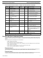
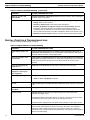
Table 2: Programmable Parameters - Ranges and Factory Defaults
Parameter
Number
Description
Factory
Default
Custom
Default Parameter Range
P-1 Operating Mode 0 0 = Auto
1 = Cool Only
2 = Heat Only
P-2 High Fan-Speed Limit 95 65 - 95
P-3 Low Fan-Speed Limit 55 30 - 75
P-4 Compressor Staging Time
Delay
15 5 - 135 seconds
P-5 Temperature-Sensor Calibration Ambient temp Ambient plus or minus 10° F
P-6 Failsafe Level 3 0 = Minimal Protection
1 = Continuous No Display
2 = Continuous With Display
3 = Four Failures Reset Required
P-7 Low AC Voltage Shutdown
(Volts)
1
115V: OFF
220/230V: OFF
115V: 75 - 105
220/230V: 175 - 205
P-8
De-Icing Cycle
2
OFF OFF
1 = On with 5°F Display Sensor Differential
2 = On with 7°F Display Sensor Differential
P-9
Pump Sentry
1
OFF OFF
On = Select 100°F to 150°F
P-10 Display Brightness Control 9 4 (Dimmest) - 13 (Brightest)
1
This feature is only available in software revision A21 and newer.
2
This feature’s setting and behavior were modified in software revision A21 and newer. See description in text for details.

Passport I/O Control Operations Manual Failsafe and Fault-Handling Codes
L-2231 ENGLISH 11
FAILSAFE AND FAULT-HANDLING CODES
To protect the equipment, certain fault conditions trigger a lockout: The control shuts down and will not restart until the fault is
repaired. The lockout condition depends on a combination of the failsafe level you have programmed as well as the type of fault
detected.
One of the following fault codes displays when a fault is detected:
• ASF – Indicates air sensor failure.
• FIL – Indicates filter needs to be cleaned or replaced.
• HPF – Indicates high refrigerant pressure. When in Heat Mode, “HPF” does not display and does not cause lockout.
• LAC – Indicates low AC voltage.
• LPF – Indicates low refrigerant pressure. “LPF” has a 10-minute shut down delay.
• PLF – Indicates high water temperature in condensing coil.
FAILSAFE LEVEL 0
This level provides minimal failsafe protection and is not recommended. Only the “ASF” fault is detected and displayed. The
control shuts down and will not restart until the fault is repaired. When the fault is repaired the control restarts.
FAILSAFE LEVEL 1
This level provides the failsafe actions of level 0, plus all other faults are detected but not displayed. The system shuts down for
2 minutes or until the fault is cleared, whichever is longer. The system restarts when the fault is cleared.
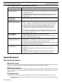
P-11 Display Temperatures in
Fahrenheit or Celsius
F F = Fahrenheit Displayed
C = Celsius Displayed
P-12 Cycle Pump With Compressor
or Continuous Pump
OFF OFF = Cycle With Compressor
On = Continuous Pump
P-13 Reverse Fan Speeds During
Heat Mode
rEF nor = Normal Fan Operation
rEF = Reversed Fan in Heat Mode
P-14 Continuous Fan or Cycle Fan
With Compressor
con CYC = Cycle Fan With Compressor
con = Continuous Fan Operation
P-15 Reverse-Cycle Heating or
Electric-Heat-Only Option
Installed
nor nor = Reverse-Cycle Heating
ELE = Electric Heater Installed
P-16 Fan-Motor Type: Split Capacitor
or Shaded Pole
SC SC = Split Capacitor Fan Motor
SP = Shaded Pole Fan Motor
P-17 Reset Memorized Programming
Defaults
nor rST = Reset Defaults
nor = Normal
P-18 Reserved for future use
P-19 Reserved for future use
P-20 Air Filter Cleaning/Replacement
Timer Setting (x10 hours)
0 0 = Timer Disabled
10 - 250 (100 - 2500 hours)
P-21 Current Filter Time (x10 hours)
and Reset
0 Displays the elapsed time (in hours x10)
since the timer was started or reset. Press
Down button to reset value to 0, restart the
timer, and clear the display’s “FIL”
reminder.
P-22 Voltage Calibration AC Voltage
P-23 Auto Mode Heat Differential OFF OFF
On = Select 4°F to 40°F
Table 2: Programmable Parameters - Ranges and Factory Defaults (continued)
Parameter
Number
Description
Factory
Default
Custom
Default Parameter Range
1
This feature is only available in software revision A21 and newer.
2
This feature’s setting and behavior were modified in software revision A21 and newer. See description in text for details.

Quick-Start Operations Checklist Passport I/O Control Operations Manual
12 L-2231 ENGLISH
FAILSAFE LEVEL 2
This level provides the failsafe actions of levels 0 and 1, plus all faults are displayed. The system shuts down for 2 minutes or
until the fault is cleared, whichever is longer. The system restarts when the fault is cleared.
FAILSAFE LEVEL 3
This level provides the failsafe actions of levels 0, 1, and 2, plus the system will lockout after four consecutive HPF or LPF
faults, and you can clear the lockout. The system shuts down for two minutes or until the fault is cleared, whichever is longer. To
clear the lockout, press the Power button once to Off Mode and press it again to On Mode.
QUICK-START OPERATIONS CHECKLIST
1. Ensure seawater-intake ball valve (seacock) is open.
2. Make sure the control is powered OFF.
3. Turn on the air conditioner circuit breaker. If the seawater pump has its own circuit breaker, turn that on also.
4. Turn the control ON.
5. Press the Fan button. Verify that the fan is running and that there is steady airflow out of the supply-air grille.
6. Select a temperature set point lower than the current cabin temperature. This starts the compressor and seawater
pump.
7. Check for a steady solid stream of water from the overboard discharge.
8. Verify that there is steady airflow out of the supply-air grille.
If the unit does not appear to be operating properly, refer to the guidelines in “TROUBLESHOOTING” on page 12.
TROUBLESHOOTING
GENERAL TROUBLESHOOTING
See also “Digital-Controls Troubleshooting” on page 14.
IMPORTANT
Do not turn the unit off then immediately turn it back on. Allow at least 30 seconds for refrigerant pressure to equalize.
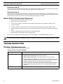
Table 3: General Troubleshooting
PROBLEM POSSIBLE REASON/SOLUTION
System will not start. 1. Air conditioner circuit breaker is off. Turn circuit breaker on at ship’s panel.
2. Digital control is not turned on. Press the Power button.
3. Wrong wiring at terminal strip. Check wiring diagram; correct if necessary.
4. Input-line voltage is insufficient. Check power source (shore/generator) for proper
voltage. Check wiring and terminals for proper sizes and connections. Verify with a
volt-meter that the power at the unit is the same as the power source.
5. Push-on connectors or butt splices became disconnected during installation.
Disconnect power supply and open electric box, check wiring diagram, correct if
necessary.
Fan is not running. Check “Digital-Controls Troubleshooting” on page 14.

Passport I/O Control Operations Manual General Troubleshooting
L-2231 ENGLISH 13
No cooling or heating. 1. Temperature set point is satisfied. Lower or raise set point.
2. Obstructed seawater flow. Clean seawater strainer. Check for obstructions at speed
scoop thru-hull inlet. Check for a good steady flow from the overboard discharge.
3. Seawater pump may be air-locked. Remove hose from pump discharge to purge air
from line.
4. Loss of refrigerant gas. Check air conditioning unit for refrigerant oil leakage, call
service technician.
5. Seawater temperature too high for cooling or too low for heating. Seawater
temperature will directly affect air conditioning unit’s efficiency. This air conditioning
unit can effectively cool your boat in water temperature up to 90°F (32.2°C) and heat
(if reverse-cycle option is installed) in water temperatures as low as 40°F (4.4°C).
6. Fan coil is iced (in cooling). Check your specific control troubleshooting section.
7. Fan is not running. Check your specific control troubleshooting section.
8. Seawater plumbing is air-locked. Ensure that seawater plumbing is installed per the
guidelines in this manual.
9. Digital control is programmed for Cool or Heat only, or mechanical-control
thermostat is rotated too far toward either Cooler or Warmer setting. See the
control’s Operations Manual for instructions.
10. High-pressure switch is open (in cooling) due to improper seawater flow.
Strainer or intake may be plugged, seacock may be closed, check seawater hose for
kinks or collapses. Verify pump operation. Check pump circuit breaker if applicable.
11. High-pressure switch is open (in heating) due to improper airflow. Remove any
obstructions in return air stream. Clean return air filter and grille. Check for crushed or
restricted ducting, ducting must be as straight, smooth and taut as possible.
12. High-pressure switch is open (in heating) due to high seawater temperature.
System may cycle on high pressure if seawater temperature is above 55°F (12.8°C).
13. Compressor’s thermal overload is open due to either of the above reasons.
Compressor needs to cool down. Turn system off for a while (it may take up to three
hours to reset thermal overload).
No heating. Unit is "cool only", or if reverse cycle, reversing valve may be stuck. Tap reversing
valve lightly with rubber mallet while unit is in heat mode. Call for service if that does not
correct the problem.
Low airflow. 1. Airflow is blocked. Remove any obstructions in return-air stream. Clean return-air
filter and grille. Check for crushed or restricted ducting; ducting must be as straight,
smooth and taut as possible.
2. Fan Coil is iced. See below.
3. Fan speed is set to manual low. If the fan speed is set to manual low, press and
release the Fan button until the desired fan speed and airflow are reached. If you
want automatic fan speed control, press and release the Fan button until the letter “A”
displays.
Fan coil is iced. 1. Thermostat set point is too low. Raise set point.
2. Improper airflow. Remove any obstructions in return air stream. Clean return air filter
and grille. Check for crushed or restricted ducting, must be as straight, smooth and
taut as possible. See the Digital Controls Troubleshooting section below for
reprogramming options.
3. Supply air is short-cycling. Redirect supply air so that is not blowing into the return
air stream. Seal any air leaks on duct.
4. Humidity level too high. Close hatches and doors.
5. When all else fails. Switch air conditioning unit to heat until ice melts or use hair
dryer to melt.
Table 3: General Troubleshooting (continued)
PROBLEM POSSIBLE REASON/SOLUTION

Digital-Controls Troubleshooting Passport I/O Control Operations Manual
14 L-2231 ENGLISH
DIGITAL-CONTROLS TROUBLESHOOTING
See also “General Troubleshooting” on page 12.
Water coil is iced in the
Heating Mode.
Seawater temperature is below 40°F (4.4°C). Shut down system to prevent damage to
condenser. Allow coil to defrost.
System runs continuously. 1. Set point temperature is improperly set: too low for cooling or too high for
heating. Raise or lower set point.
2. Porthole or hatches open. Close all port holes and hatches.
3. Seawater temperature too high for cooling or too low for heating. Seawater
temperature will directly affect the air conditioning unit’s efficiency. This air
conditioning unit can effectively cool your boat in water temperatures up to 90°F
(32.2°C) and heat (if reverse cycle option is installed) in water as low as 40°F (4.4°C).
4. Improper air sensor location. Check your specific control troubleshooting section.
Table 4: Digital-Controls Troubleshooting
PROBLEM POSSIBLE REASON/SOLUTION
Digital display panel is not
lit.
The 8-pin display-cable plugs are not making contact (unplugged, dirty, bent, or
broken pins). With POWER OFF at the circuit breaker, remove connector and inspect. If
damaged, replace connector or entire display cable.
Fan is not running or runs
continuously.
Digital control is programmed for either fan cycling with compressor or continuous
fan operation. Reprogram parameter P-14. Note: When configured for electric heat, after
a heat cycle ends the fan will stay on for 4 minutes even if the fan is set to cycled
operation.
Fan is not running but the
compressor is .
Failed triac on circuit board. Send for repair or call local service technician.
Fan runs continuously
although it is set to cycle
with compressor.
Failed triac on circuit board. Send for repair or call local service technician.
No cooling or heating. 1. Digital control programmed for heat or cool only. Reprogram parameter P-1.
2. "HPF" or "LPF" is displayed. See below.
No heat. Digital Control may be set to Electric Heat, not Reverse Cycle. Reprogram parameter
P-15.
Unit switches to heat while in
Cool Mode.
De-icing feature enabled due to coil icing up. Reprogram parameter P-8
Fan coil is iced. Improper airflow. See the General Troubleshooting section above first, before
reprogramming digital control.
Reprogram parameter P-8 to enable de-icing. If de-icing cycle does not melt ice, switch
air conditioning unit to heat until ice melts or use hair dryer to melt ice.
If problem persists, reprogram Low Fan Speed Limit for maximum value. Set P-3 to 64.
System runs continuously. Improper air sensor location. Verify display head location with criteria found in the
control manual. Install alternate air sensor if necessary. Ensure the control display is
located out of direct sunlight and away from open doors or hatches. Or, if using an
alternate air sensor, ensure the sensor is located directly in the system’s return-air path to
obtain an accurate reading.
Table 3: General Troubleshooting (continued)
PROBLEM POSSIBLE REASON/SOLUTION

Passport I/O Control Operations Manual System Components
L-2231 ENGLISH 15
MAINTENANCE
SYSTEM COMPONENTS
REVERSING VALVE
Reverse-cycle (cooling and heating) units have a reversing valve that must be energized periodically to keep the internal parts
moving freely. To do this, switch the air conditioner unit into Heat Mode for a few seconds once a month.
SEAWATER STRAINER
Ensure your pump receives adequate seawater flow by regularly cleaning the strainer basket. Periodically check the overboard
discharge for a steady stream of water. Check seawater intake speed scoop for obstructions. Make sure hoses are not looped,
kinked or crushed.
CONDENSER COIL
A marine-growth-fouled coil reduces efficiency, raising total system pressure and decreasing its ability to produce cold air.
1. With the system turned off at the circuit breaker on the ship’s panel, disconnect the inlet and outlet connections of the
condenser coil.
"ASF" is displayed.
(Air Sensor Failure)
1. Indicates failed face plate air sensor, alternate air sensor or display cable.
Unplug alternate air sensor if installed or plug in alternate air sensor if not installed.
Try another display cable.
2. Damaged jack/socket in display head or on circuit board. Visually check to see
that pins inside socket are not bent or corroded. Repair or replace display or circuit
board if needed.
"FIL" is flashing
(Filter Reminder)
Filter needs to be cleaned or replaced. Clean or replace filter, and reset P-21 to "00”.
"HPF" is displayed.
(High Refrigerant Pressure)
1. High-pressure switch is open (in cooling) due to improper seawater flow.
Strainer or intake may be plugged, seacock may be closed. Check seawater hose for
kinks or collapses. Verify pump operation; check pump circuit breaker if applicable.
2. High-pressure switch open (in heating) due to improper airflow. Remove
obstructions in return air stream. Clean air filter and grille. Check for crushed or
restricted ducting. Ducting must be as straight, smooth and taut as possible.
If problem persists, reprogram Low Fan Speed Limit for maximum value. Set P-3 to
64, and set the reverse fan speeds during Heating Mode parameter P-13 to “rEF", or
manually set fan speed to high.
"LAC" is displayed.
(Low AC Voltage)
1. Supply voltage is too low. Verify power to unit with multimeter.
2. Voltage is improperly calibrated. Verify that P-22 matches voltage reading to unit
with a multimeter. Adjust P-22 if necessary.
"LPF" is displayed.
(Low Refrigerant Pressure)
1. Low-pressure switch is open due to low seawater and/or low return air
temperatures. Try restarting the air conditioning unit, the optional low pressure
switch has a ten minute shutdown time delay that may be in effect.
2. Low pressure switch is open due to loss of refrigerant. Check air conditioning unit
for refrigerant oil leakage, call service technician.
"PLF" is displayed.
(Low Pump Flow)
1. Condenser coil is too hot. Verify that unit is getting water flow, and that condenser is
not fouled.
2. Thermistor is damaged. Unplug water sensor if installed. Try another if it is
available.
3. Damaged jack/socket on circuit board. Visually check to see that pins inside
socket are not bent or corroded. Repair or replace circuit board if needed.
Table 4: Digital-Controls Troubleshooting (continued)
PROBLEM POSSIBLE REASON/SOLUTION

Automated Factory Self-Test Program Passport I/O Control Operations Manual
16 L-2231 ENGLISH
2. Use chemical-resistant hoses (white PVC 5/8" I.D., etc.) to connect the inlet of the condenser coil to the outlet of a
chemical resistant, submersible pump (P-500 pump, etc.) and let the hose connected to the coil outlet flow freely into
the container mentioned below.
3. Place a strainer or piece of screen over the inlet of the pump and submerse the pump into a container filled with a 5%
solution of muriatic or hydrochloric acid and fresh water or use a premixed over-the-counter solution. Use as large a
container as possible to hold the solution (5-25 gallons [19-95 liters]).
4. Power the pump and circulate the solution through the condenser coil for 15-45 minutes depending upon the size of
the coils and the extent of the contamination. Visual inspection of the solution in the container should indicate when the
contamination removal has stopped.
5. Circulate fresh water through the coil to flush any residual acid from the system.
6. Restart the system and check operational parameters to ensure thorough cleaning has taken place. Additional
cleaning may be necessary with extreme contamination.
RETURN-AIR FILTER
Check the return-air filter about once a month and clean as necessary. To clean the filter, remove it from the unit, rinse with
water, air dry and reinstall.
WINTERIZATION
There are several methods of winterization, some of which work better than others. Any method that causes the antifreeze
solution to flow downward is the method of choice. By this means, the antifreeze solution displaces any trapped water and
eliminates the possibility of it freezing in hidden areas.
Choose the method that works best for you. In the following four methods, the first two use a 50/50 nonpolluting biodegradable
antifreeze/water solution:
• Pump antifreeze solution into the overboard thru-hull fitting, and discharge through the intake thru-hull fitting.
• Use the seawater pump to pump antifreeze solution through the system and discharge through the overboard thru-hull
fitting: Close seacock, remove hose from strainer discharge, raise hose above pump (so pump does not lose its prime)
and pour in antifreeze solution. Pump solution through system. The strainer and hose to seacock need to be drained of
water.
• Use pressurized air injected at the overboard discharge fitting to force system water through the seawater intake fitting,
thus expelling any trapped water from the system.
• Use pressurized air injected at the seawater intake fitting to force system water through the seawater overboard
discharge fitting, thus expelling any trapped water from the system.
In addition, since the seawater pump utilizes a magnetically driven impeller, remove the impeller from the wet-end assembly,
wipe with an alcohol solution, and store in a warm, dry area until commissioning takes place.
AUTOMATED FACTORY SELF-TEST PROGRAM
The Passport I/O software contains a self-test program to facilitate factory testing of the entire air conditioning system. Once the
self-test program is activated, the test cycle continues until the AC power is interrupted or the Power button is pressed once,
which returns the system to Off Mode.
To activate the self-test program, disconnect the AC power, then press and hold the Power button while restoring the AC
power. During Power-On Reset (the display indicates “888” and all LEDs are lit), release the Power button. The control is now in
the self-test program and “tSt” appears in the display.
Once activated, the self-test software continuously executes the following commands:
CAUTION
Avoid spilling or splashing the solution. Follow all warnings and recommendations given by the manufacturer of any
acids or premixed solutions.
NOTE
For the purpose of protecting the environment, dispose of any contaminated acid solutions in accordance with
federal, state and/or local regulations.
NOTE
Collect all discharged liquids and recycle or dispose of in a proper manner in accordance with federal, state and/or
local regulations.

Passport I/O Control Operations Manual Service Utilities
L-2231 ENGLISH 17
1. Turn on Heat Mode and supply heating for ten minutes.
2. Stop heating and run only the fan for five minutes.
3. Switch to Cool Mode and continue cooling for ten minutes.
4. Stop cooling and run only the fan for five minutes.
5. Return to step one and repeat procedure until interrupted.
To halt the self-test program, press the Power button once or interrupt the flow of AC power.
SERVICE UTILITIES
HOUR METER
The Hour Meter provides a way to judge a compressor’s longevity based on actual run time. Total compressor-cycle time is
saved in EEPROM every six minutes of continuous compressor running time. Cycle times of less than six minutes are discarded
to conserve memory and allow the most flexible Hour Meter possible.
To view the Hour Meter, disconnect AC power then press the Down button. While holding the Down button, restore AC power.
After Power-On Reset is complete (the display indicates “888” and all LEDs are lit), the following Hour Meter information
appears in the display:
1. “Hr” displays for one second.
2. The display blanks out for one second then displays for three seconds a two-digit number representing thousands of
hours. (For example, a display of “02” equals 2,000 hours.)
3. The display blanks out for one second then displays for three seconds a three-digit number representing hundreds,
tens, and ones of hours. (For example, a display of “163” equals 163 hours. Combined with the example above, the
complete Hour Meter reading is 2,163 hours.)
4. The display returns to its last operating state before power was removed.
Maximum recordable time is 65,536 hours, at which point the meter stops and can only be reset by a service technician.
SERVICE HISTORY LOG
The control records and remembers the eight most recent faults. Each time a fault is detected, a one-hour timer starts. Three
consecutive faults within that hour cause system shut down, lockout, and the fault code displays.
The following events are entered into the service history log:
• High Refrigerant Pressure (HPF)
• Low Refrigerant Pressure (LPF)
• Air Sensor Failure (ASF)
• Low AC Voltage (LAC)
• Pump or Loss of Seawater (PLF)
During the timed hour, to conserve memory, recurring faults of the same type are not recorded in the service history log.
Continuous operation for one hour without the same recurring fault clears that fault counter, but the event remains in the service
history log until overwritten. If a different fault is detected during the hour, it is also entered into the service history log.
• To view the service history log, disconnect AC power then press the Fan button. With the Fan button pressed,
restore AC power. When Power-On Reset is complete (the display indicates “888” and all LEDs are lit), release the
Fan button. The display flashes the most recently detected fault, followed by the event chronology number. To view
other detected events, press the Up button or the Down buttons.
• To clear the service history log, simultaneously press the Power and Down buttons.
• To exit the service history log, press the Power button or wait thirty seconds without pressing any button.

Operational Passport I/O Control Operations Manual
18 L-2231 ENGLISH
SPECIFICATIONS
OPERATIONAL
Set Point Operating Range. . . . . . . . . . . . . . . . . . . . . . . . . . . . . . . . 65°F to 85°F (18.3°C to 29.4°C)
Ambient Temperature Operating Range Displayed . . . . . . . . . . . . . . 5°F to 150°F (-15°C to 65.6°C)
Sensor Accuracy . . . . . . . . . . . . . . . . . . . . . . . . . . . . . . . . . . . . . . . .± 2°F @ 77°F (±1.1°C @ 25°C)
Low Voltage Limit 115 Volt Units . . . . . . . . . . . . . . . . . . . . . . . . . . . . . . . . . . . . . . . . . . . . . . .75 VAC
Low Voltage Limit 220 Volt Units . . . . . . . . . . . . . . . . . . . . . . . . . . . . . . . . . . . . . . . . . . . . . .175 VAC
Low Voltage Processor Reset. . . . . . . . . . . . . . . . . . . . . . . . . . . . . . . . . . . . . . . . . . . . . . . . . .50 VAC
Line Voltage . . . . . . . . . . . . . . . . . . . . . . . . . . . . . . . . . . . . . . . . . . . . . . . . . . . 115 Through 240 VAC
Frequency. . . . . . . . . . . . . . . . . . . . . . . . . . . . . . . . . . . . . . . . . . . . . . . . . . . . . . . . . . . . . 50 or 60 Hz
Fan Output . . . . . . . . . . . . . . . . . . . . . . . . . . . . . . . . . . . . . . . . . . . . . . . . . . . . . . 6 Amps @ 115 VAC
Fan Output . . . . . . . . . . . . . . . . . . . . . . . . . . . . . . . . . . . . . . . . . . . . . . . . . . . . . .6 Amps @ 230 VAC
Valve Output . . . . . . . . . . . . . . . . . . . . . . . . . . . . . . . . . . . . . . . . . . . . . . . . . 1/4 Amp @ 115/230 VAC
For Passport I/O circuit boards revision F and newer and U-boards:
Heater Output (using valve relay). . . . . . . . . . . . . . . . . . . . . . . . . . . . . . . . . . . . 15 Amps @ 115 VAC
Heater Output (using valve relay). . . . . . . . . . . . . . . . . . . . . . . . . . . . . . . . . . . . . . 10 Amps @ 230 V
For Passport I/O circuit boards revision E and older:
Heater Output (using heater relay) . . . . . . . . . . . . . . . . . . . . . . . . . . . . . . . 30 Amps @ 115 VAC
Heater Output (using heater relay) . . . . . . . . . . . . . . . . . . . . . . . . . . . . . . . . . 20 Amps @ 230 V
Pump Output . . . . . . . . . . . . . . . . . . . . . . . . . . . . . . . . . . . . . . . . . . . . . . . . . . . . 1/4 HP @ 115 VAC
Pump Output . . . . . . . . . . . . . . . . . . . . . . . . . . . . . . . . . . . . . . . . . . . . . . . . . . . . 1/2 HP @ 230 VAC
Compressor Output . . . . . . . . . . . . . . . . . . . . . . . . . . . . . . . . . . . . . . . . . . . . . . . . . 1 HP @ 115 VAC
Compressor Output . . . . . . . . . . . . . . . . . . . . . . . . . . . . . . . . . . . . . . . . . . . . . . . . . 2 HP @ 230 VAC
Minimum Operating Temperature . . . . . . . . . . . . . . . . . . . . . . . . . . . . . . . . . . . . . . . . . 0°F (-17.8°C)
Maximum Ambient Operating Temperature . . . . . . . . . . . . . . . . . . . . . . . . . . . . . . . . .180°F (82.2°C)
Maximum Rh Conditions. . . . . . . . . . . . . . . . . . . . . . . . . . . . . . . . . . . . . . . . . . 99% Non Condensing
Power Consumption . . . . . . . . . . . . . . . . . . . . . . . . . . . . . . . . . . . . . . . . . . . . . . . .Less Than 5 Watts
DIMENSIONS
Compact model - Display Panel . . . . . . . . . . . . . . . . . . . . . . . . . . . . . . 3.19” (82mm) X 2.5" (64mm)
Compact model - Panel Cut Out . . . . . . . . . . . . . . . . . . . . . . . . . . . . 2.5" (63mm) X 1.875" (48mm)
Legacy model - Display Panel. . . . . . . . . . . . . . . . . . . . . . . . . . . 4.5" (114mm) X 3.86" (98mm) high
Legacy model - Panel Cutout . . . . . . . . . . . . . . . . . . . . . . . . . . . . . 3.375" (86mm) X 2.875" (73mm)
CABLE LENGTHS
Display Cable Self Contained . . . . . . . . . . . . . . . . . . . . . . . . . . . . . . . . . . . . . . . . 15' (4.6m) Standard
Display Cable Central System . . . . . . . . . . . . . . . . . . . . . . . . . . . . . . . . . . . . . . . 30' (9.1m) Standard
Alternate Air Sensor (optional) . . . . . . . . . . . . . . . . . . . . . . . . . . . . . . . . . . . . . . . . 7' (2.1m) Standard
Alternate Air Sensor Central System (optional) . . . . . . . . . . . . . . . . . . . . . . . . . . 30' (9.1m) Standard
Outside Air Sensor (optional) . . . . . . . . . . . . . . . . . . . . . . . . . . . . . . . . . . . . . . . . 15' (4.6m) Standard
All custom cable lengths supplied in standard 5' (1.5m) increments . . . . . . . . 75' (22.9m) Maximum
SYSTEM INPUTS
Ambient or Inside-Air Temperature. . . . . . . . . . . . . . . . . . . . . . . . . . . . . . . . . . . . . . . . . . . . . . . . . . .1
High Refrigerant Pressure . . . . . . . . . . . . . . . . . . . . . . . . . . . . . . . . . . . . . . . . . . . . . . . . . . . . . . . . . 1
Low Refrigerant Pressure (optional). . . . . . . . . . . . . . . . . . . . . . . . . . . . . . . . . . . . . . . . . . . . . . . . . .1
Alternate Inside-Air Temperature Sensor (optional) . . . . . . . . . . . . . . . . . . . . . . . . . . . . . . . . . . . . . .1
Outside-Air Temperature Sensor (optional) . . . . . . . . . . . . . . . . . . . . . . . . . . . . . . . . . . . . . . . . . . . .1
Pump Sentry Condenser Coil Sensor (optional). . . . . . . . . . . . . . . . . . . . . . . . . . . . . . . . . . . . . . . . .1
NOTE
Maximum length of display and sensor cables is 75 feet (22.9m). The outside-air sensor and alternate air sensor are
optional items and are not included with the standard control package.
Page is loading ...
Page is loading ...
Page is loading ...
Page is loading ...
-
 1
1
-
 2
2
-
 3
3
-
 4
4
-
 5
5
-
 6
6
-
 7
7
-
 8
8
-
 9
9
-
 10
10
-
 11
11
-
 12
12
-
 13
13
-
 14
14
-
 15
15
-
 16
16
-
 17
17
-
 18
18
-
 19
19
-
 20
20
-
 21
21
-
 22
22
-
 23
23
-
 24
24


Dometic Passport I/O Digital Control Operating instructions
- Category
- Split-system air conditioners
- Type
- Operating instructions
- This manual is also suitable for
Ask a question and I''ll find the answer in the document
Finding information in a document is now easier with AI
Related papers
-
Dometic Passport I/O Digital Controls Operating instructions
-
-
-
-
-
-
-
-
-
Other documents
-
Webasto FCF 16 Operating instructions
-
Sinclair ASB-24A User manual
-
 Micro Air Corporation FX2-DX Operating instructions
-
Regal 3760 Owner's manual
-
 Cruisair SMX Online User manual
-
Webasto FCF 6,000 BTU Operating instructions
-
Vector TLR-D5P-230 Engineering Manual
-
Mindray Passport V User manual
-
-
Simplicity 953 User guide

