Page is loading ...

FPI FIREPLACE PRODUCTS INTERNATIONAL LTD. 6988 Venture St., Delta, BC Canada, V4G 1H4
920-004b
Regency Horizon
®
HZ54E
Gas Fireplace
05.29.19
Owners &
Installation Manual
www.regency-re.com
MODELS: HZ54E-NG11 Natural Gas
HZ54E-LP11 Propane
Horizon HZ54E Product Video
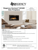
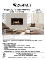
- Do not store or use gasoline or other flammable vapors and liquids in the vicinity of this or any other appliance.
- WHAT TO DO IF YOU SMELL GAS
• Do not try to light any appliance.
• Do not touch any electrical switch: do not use any phone in your building.
Leave the building immediately.
• Immediately call your gas supplier from a neighbour's phone. Follow the gas supplier's
instructions.
• If you cannot reach your gas supplier, call the fire department.
- Installation and service must be performed by a qualified installer, service agency or the gas supplier.
WARNING
FIRE OR EXPLOSION HAZARD
failure to follow safety warnings exactly could result in serious
injury, death, or property damage.
Installer: Please complete the details on the back cover
and leave this manual with the homeowner.
Homeowner: Please keep these instructions for future reference.
Certified to/Certifié pour: CSA 2.17-2017
ANSI Z21.88-2017
CSA 2.33-2017
Tested by:

2 | Regency Horizon
®
HZ54E-11 Gas Fireplace
To the New Owner:
Congratulations!
You are the owner of a state-of-the-art Gas Fireplace by REGENCY
®
. The HZ54E has been designed to provide
you with all the warmth and charm of a wood fireplace at the flick of a switch. The model HZ54E has been
approved by Warnock Hersey/Intertek for both safety and efficiency. As it also bears our own mark, it promises
to provide you with economy, comfort and security for many trouble free years to follow. Please take a moment
now to acquaint yourself with these instructions and the many features of your Regency
®
Fireplace.
On Demand Pilot Light (seven day safety timer)
Important information if using the appliance in CPI (continuous pilot mode) only.
This appliance is a ProFlame 1 system fitted with the “On Demand” Pilot, a safety feature which will shut down the gas valve com-
pletely by extinguishing the pilot light in the event of a continuous full seven days of inactivity.
This only applies if the CPI (continuous pilot) switch is in the “on” position.
Each time the main burner shuts down, manually or through the call from the thermostat, the seven day timer starts again.
The seven day inactivity timer is controlled within the circuit board. Therefore, if in CPI mode and when the pilot light is extinguished
after seven straight days of inactivity, the IPI/CPI rocker switch will remain in the “on” position. Therefore, all that is required to relight
the pilot would be to press the on/off button on the remote control transmitter from “on” to “off” and back to “on”. Once the pilot has
re-established operation will resume as normal. There is no requirement to do anything with the IPI/CPI rocker switch.
If the unit never goes as long as seven full days without a call for heat, the pilot will remain lit until it is manually shut-off.
If the unit is being operated in IPI (intermittent pilot) mode, neither the above instructions nor the seven day timer will apply.
See the instructions in this manual and on the Lighting Instructions plate on the appliance to light or re-light the pilot.

Regency Horizon
®
HZ54E-11 Gas Fireplace | 3
This appliance can only be used with the type of gas indicated on the rating plate.
This appliance is not convertible for use with other gases.
This appliance may be installed as an OEM installation in a manufactured home (USA only) or mobile home and must be
installed in accordance with the manufacturer's instruction and the Manufactured Home Construction and Safety Standard,
Title 24 CFR, Part 3280, in the Untied States, or the Standard for Installation in Mobile Homes, CAN/CSA Z240 MH, in
Canada.
MANUFACTURED MOBILE HOME REQUIREMENTS
INFORMATION FOR MOBILE/MANUFACTURED HOMES AFTER FIRST SALE
This appliance may only be installed in an aftermarket permanently located, manufactured (U.S.A only) or mobile home,
where not prohibited by local codes.
This Direct Vent System Appliance must be installed in accordance with the manufacturer's installation instructions and the
Manufactured Home Construction and Safety Standard, Title 24 CFR, Part 3280, or the current Standard of Fire Safety Criteria
for Manufactured Home Installations, Sites, and Communities ANSI/NFPA 501A, and with CAN/CSA Z240-MH Mobile Home
Standard in Canada.
This appliance installation must comply with the manufacturer's installation instructions and local codes, if any. In the absence
of local codes follow the current National Fuel Gas Code, ANSI Z223.1 and the current National Electrical Code ANSI/NFPA
70 in the U.S.A., and the current CAN/CGA B149 Gas Installation Code and the current Canadian Electrical Code CSA C22.1
in Canada.
This appliance comes equipped with a dedicated #8 Ground Lug for attachment of the ground wire to the steel chassis as
applicable to local codes.
The appliance, when installed, must be electrically grounded in accordance with local codes or, in the absence of local codes,
with the National Electrical Code, ANSI/NFPA 70, or the Canadian Electrical Code, CSA C22.1.
Ensure that structural members are not cut or weakened during installation.
Regency Horizon
Gas Inserts Benets Video
Horizon HZ54 Product Video
This Regency
®
product has been tested and listed by Warnock Hersey/Intertek as a Direct Vent Wall Furnace to the following
standards: VENTED GAS FIREPLACE HEATERS ANSI Z21.88-2017 / CSA 2.33-2017 and GAS-FIRED APPLIANCES FOR
USE AT HIGH ALTITUDES CSA 2.17-2017.

4 | Regency Horizon
®
HZ54E-11 Gas Fireplace
table of contents
On Demand Pilot Light (seven day safety timer) ........................ 2
Copy of Safety Decal .....................................................5
MA Code - CO Detector ................................................6
(for the State of Massachusetts only) ............................6
Unit Dimensions ............................................................7
Faceplate & Door frame overlay Dimensions ................7
Important Message ......................................................8
Before You Start .............................................................8
General Safety
Information .....................................................................8
Lighting Procedure ........................................................9
Copy of Lighting Plate Instructions ..............................10
proflame i remote control operating instructions ..........11
warranty .......................................................................65
Installation Checklist ....................................................15
Locating Your Gas Fireplace ........................................15
Heatwave Duct System ...............................................15
Heat Release kit ..........................................................15
Clearances ..................................................................16
Non-Combustible Requirements..................................16
Non combustible facing board .....................................17
Non-combustible facing installation ............................17
Mantel Clearances .......................................................18
Mantel Leg Clearances ................................................18
Framing & Finishing .....................................................19
Unit Assembly Prior To Installation ..............................20
Standoff Assembly ...............................................20
Nailing Strips........................................................20
Venting Introduction .....................................................20
Framing Dimensions ....................................................21
Wall mount On / Off Switch / receiver installation ........23
Vent Restrictor Position ...............................................24
Exterior Vent Termination Requirements .....................25
Venting Arrangements ................................................26
Horizontal Termination (Flex) ...............................26
Rigid Pipe Venting Systems .........................................27
Basic Horizontal & Vertical Terminations .............27
5” x 8” Rigid Pipe Cross Reference Chart ...................28
Venting Arrangements ................................................30
Allowable Horizontal ...........................................30
Terminations for HZ54E-NG ................................30
Venting Arrangements ................................................30
Allowable Horizontal ...........................................30
Terminations for HZ54E-LP .................................30
Venting Arrangements ................................................33
Allowable Vertical Terminations for HZ54E-NG ....33
ALL PICTURES / DIAGRAMS SHOWN THROUGHOUT THIS MANUAL ARE FOR ILLUSTRATION PURPOSES ONLY.
ACTUAL PRODUCT MAY VARY DUE TO PRODUCT ENHANCEMENTS.
owner's information
installer's information
Venting Arrangements ................................................34
Allowable Vertical Terminations for HZ54E-LP .....34
Unit Installation with Horizontal Termination ................35
Unit Installation with Vertical Termination ....................36
Unit Installation ............................................................37
Horizontal Termination .........................................37
with Flex Vent System ..........................................37
AstroCap XL Dimensions (946-623/P) ........................37
High Elevation ..............................................................38
Gas Line Installation ....................................................38
Pilot Adjustment ...........................................................38
Gas Pipe Pressure Testing ..........................................38
885 S.I.T. Valve Description .........................................38
Valve cover removal .....................................................39
Aeration Adjustment ....................................................40
Wiring Diagram ............................................................41
Optional wall thermostat installation ............................42
Optional Reflective Panel Installation ..........................43
Glass Crystals or optional stones ................................44
Installation On Burner ..................................................44
Optional Pebbles / GLASS crystal Installation for
Firebox Base (AROUND BURNER) ............................44
Optional driftwood Log set Installation .........................45
Faceplate & Door frame overlay Installation ................47
Fan Installation ............................................................50
Wiring diagram with optional fan .................................53
Operating Instructions .................................................54
First Fire ......................................................................54
Normal Operating Sounds of Gas Appliances .............54
Lighting Procedure ......................................................55
Copy of Lighting Plate Instructions ..............................56
Maintenance Instructions ............................................57
General Vent Maintenance ..........................................57
Glass Gasket ...............................................................57
Glass Door ...................................................................57
Glass Replacement .............................................57
Glass Door Removal....................................................58
Safety screen removal / installation .............................59
Valve Tray Replacement ..............................................60
HZ54E-NG unit ............................................................61
HZ54E-LP unit .............................................................62
Main Assembly ............................................................63
Accessories .................................................................65

Regency Horizon
®
HZ54E-11 Gas Fireplace | 5
safety decal
Copy of Safety Decal
Decal location
For the State of Massachusetts, installation
and repair must be done by a plumber or
gas fitter licensed in the Commonwealth of
Massachusetts.
For the State of Massachusetts, flexible con-
nectors shall not exceed 36 inches in length.
For the State of Massachusetts, the appli-
ances individual manual shut-off must be a
t-handle type valve.
The State of Massachusetts requires the
installation of a carbon monoxide alarm in
accordance with NFPA 720 and a CO alarm
with battery back up in the same room where
the gas appliance is installed.
DO NOT REMOVE THIS LABEL /
NE PAS ENLEVER CETTE ÉTIQUETTE
503
503
DOOR SEAL: Please
check that the door is
properly sealed
FPI Fireplace Products International Ltd. Delta, BC, Canada
Minimum Clearances to Combustibles /
Dégagements minimaux par rapport aux matériaux combustibles
Serial No./ No de série
.
NOT FOR USE WITH SOLID FUEL / NE PAS UTILISER AVEC UN COMBUSTIBLE SOLIDE
Made in Canada/ Fabriqué au Canada
Duplicate S/N
(See Instruction Manual for
detailed instructions)
APPAREIL FONCTIONNANT AU GAZ PROPANE
Modèle HZ54E-LP11
PROPANE GAS: Model HZ54E-LP11
Pression d'alimentation minimale
Pression manifold - basse
Pression manifold maximale
Taille de l’orifice
D bit calorifique minimalé
D bit calorifique maximalé
Altitude
Pression d'alimentation minimale
Pression manifold - basse
Pression manifold max.
Taille de l’orifice
D bit calorifique minimalé
D bit calorifique maximalé
Altitude
D
E
F
A
B
C
Side Walls/Murs latéraux
A 4” (102mm)
Ceiling/Plafond
B 40-7/8” (1038mm)
Min. Mantel Height/Hteur manteau min.
C 20" (508mm)
Max. Mantel Depth/Prof. manteau max.
D 13” (330mm)
Alcove Width/Largeur alcôve
E 83" (2108mm)
Alcove Depth/Prof. alcôve
F 36" (914mm)
This appliance must be installed in accordance with local codes, if any; if none, follow the National Fuel Gas Code, ANSI Z223.1, or Natural Gas and Propane Installation Code, CSA B149.1.
This appliance must be installed in accordance with the Standard CAN/CSA Z240 MH, Mobile Housing, in Canada, or with the Manufactured Home Construction and Safety Standard, Title 24 CFR, Part 3280, in
the United States, or when such a standard is not applicable, ANSI/NCSBCS A225.1/NFPA 501A, Manufactured Home Installations Standard or ANSI A119.2 ou NFPA 501C Standard for Recreational Vehicles
This appliance is only for use with the type of gas indicated on the rating plate and may be installed in an aftermarket, permanently located, manufactured (mobile) home where not prohibited by local codes. See
owner's manual for details.
Installer l'appareil selon les codes ou règlements locaux, ou, en l'absence de tels règlements, selon les codes d'installation ANSI Z223.1, National Fuel Gas Code ou CSA-B149.1 en vigueur.
Installer l'appareil selon la norme CAN/CSA-Z240, Série MM, Maison mobiles ou CAN/CSA-Z240 VC, Véhicules de camping, ou la norme 24 CFR Part 3280, Manufactured Home Construction and Safety
Standard. Si ces normes ne sont pas pertinentes, utilisez la norme ANSI/NCSBCS A225.1/NFPA 501A, Manufactured Home Installations Standard, ou ANSI A119.2 ou NFPA 501C Standard for Recreational
Vehicles.
Cet appareil doit être utilisé uniquement avec le type de gaz indiqué sur la plaque signalétique. Il peut être installé dans une maison préfabriquée ou mobile (É.-U. seulement) installée à demeure si les
règlements locaux le permettent. Voir le guide de l'utilisateur pour plus de renseignements.
This vented gas fireplace heater is not for use with air filters. Ne pas utiliser de filtre à air avec ce foyer au gaz à évacuation.
For Use Only with Barrier (Part # 478-013) Follow installation instructions. Utiliser uniquement avec un écran de protection ( n°478-013). Suivre les consignes d'installation.
FOR USE WITH GLASS DOORS CERTIFIED WITH THE APPLIANCE ONLY À UTILISER UNIQUEMENT AVEC LES PORTES VITRÉES CERTIFIÉES AVEC L'APPAREIL
Min. Supply Pressure 11"WC (2.74 kpa)
Low Setting Man. Pressure 6.4"WC (1.59 kpa)
Max. Manifold Pressure 10"WC (2.49 kpa)
Orifice Size #49 DMS
Minimum Input 30,000Btu/ (8.79 kW)
Maximum Input 37,000Btu/h (10.84 kW)
Altitude 0-4500 ft/pi (0-1372 m)
Part #: 920-005a
Colour: Black on grey except what is indicated as being printed red.
Size: 9.114” W x 6.017” H (File at 100%)
Material: 2 ml silver matt polyester (DPM SMS)
Dec 17/18: Created decal
Jan. 22/19: Rev A - Remodeled decal and added ETL logo at the bottom
Printer: Start number sequence @005000001
Min. Supply Pressure 5“ WC (1.25 kpa)
Low Setting Man. Pressure 1.6"WC (0.40 kpa)
Max. Manifold Pressure 3.5"WC (0.87 kpa)
Orifice Size #30DMS
Minimum Input 29,000Btu/h (8.50 kW)
Maximum Input 41,500 Btu/h (12.16 kW)
Altitude 0-4500 ft/pi (0-1372 m)
NATURAL GAS: Model HZ54E-NG11
MAY BE INSTALLED IN MANUFACTURED (MOBILE) HOMES AFTER FIRST SALE.
Listed/Nom: VENTED GAS FIREPLACE HEATERS / APPAREIL DE CHAUFFAGE AU GAZ À ÉVACUATION.
Certified to/Certifi : é
ANSI Z21.88-2017 • CSA-2.33-2017
CSA 2.17-2017
Refer to Intertek's Directory of Building Products for detailed information.
Pour plus de détails, se reporter au Répertoire des produits de construction de Intertek.
APPAREIL FONCTIONNANT AU GAZ NATUREL
Modèle HZ54E-NG11
C #: 4001172
920-005a
CSA P.4.1 Fireplace Efficiency (FE) /
Efficacité énergétique des foyers (EEF) CSA P.4.1
Natural Gas / Gaz naturel 64.45%
Propane Gas / Gaz propane 67.72%
CANADIAN ENERGY
PERFORMANCE
VERIFIED
RENDEMENT
ÉNERGÉTIQUE
VÉRIFIÉ
EP5011169
This is a copy of the label that accompanies each HZ54E-NG11 / HZ54E-LP11 Direct Vent Gas Fireplace. We have printed a copy of the contents here for
your review.
NOTE: Regency
®
units are constantly being improved. Check the label on the unit and if there is a difference, the label on the unit is the correct one.
Remove outer faceplate and door (see manual for
instructions) once the Faceplate and Glass door have
been removed the rating plate will be attached to a chain.
DO NOT REMOVE DECAL FROM UNIT.

6 | Regency Horizon
®
HZ54E-11 Gas Fireplace
requirements
5.08: Modifications to NFPA-54, Chapter 10
(2) Revise 10.8.3 by adding the following additional requirements:
(a) For all side wall horizontally vented gas fueled equipment installed in every dwelling, building or structure used in whole or in part for
residential purposes, including those owned or operated by the Commonwealth and where the side wall exhaust vent termination is less than
seven (7) feet above finished grade in the area of the venting, including but not limited to decks and porches, the following requirements shall
be satisfied:
1. INSTALLATION OF CARBON MONOXIDE DETECTORS. At the time of installation of the side wall horizontal vented gas fueled
equipment, the installing plumber or gasfitter shall observe that a hard wired carbon monoxide detector with an alarm and battery back-up is
installed on the floor level where the gas equipment is to be installed. In addition, the installing plumber or gasfitter shall observe that a battery
operated or hard wired carbon monoxide detector with an alarm is installed on each additional level of the dwelling, building or structure
served by the side wall horizontal vented gas fueled equipment. It shall be the responsibility of the property owner to secure the services of
qualified licensed professionals for the installation of hard wired carbon monoxide detectors
a. In the event that the side wall horizontally vented gas fueled equipment is installed in a crawl space or an attic, the hard wired carbon
monoxide detector with alarm and battery back-up may be installed on the next adjacent floor level.
b. In the event that the requirements of this subdivision can not be met at the time of completion of installation, the owner shall have a period of
thirty (30) days to comply with the above requirements; provided, however, that during said thirty (30) day period, a battery operated carbon
monoxide detector with an alarm shall be installed.
2. APPROVED CARBON MONOXIDE DETECTORS. Each carbon monoxide detector as required in accordance with the above provisions
shall comply with NFPA 720 and be ANSI/UL 2034 listed and IAS certified.
3. SIGNAGE. A metal or plastic identification plate shall be permanently mounted to the exterior of the building at a minimum height of eight
(8) feet above grade directly in line with the exhaust vent terminal for the horizontally vented gas fueled heating appliance or equipment. The
sign shall read, in print size no less than one-half (1/2) inch in size, "GAS VENT DIRECTLY BELOW. KEEP CLEAR OF ALL
OBSTRUCTIONS".
4. INSPECTION. The state or local gas inspector of the side wall horizontally vented gas fueled equipment shall not approve the installation
unless, upon inspection, the inspector observes carbon monoxide detectors and signage installed in accordance with the provisions of 248 CMR
5.08(2)(a)1 through 4.
(b) EXEMPTIONS: The following equipment is exempt from 248 CMR 5.08(2)(a)1 through 4:
1. The equipment listed in Chapter 10 entitled "Equipment Not Required To Be Vented" in the most current edition of NFPA 54 as adopted by
the Board; and
2. Product Approved side wall horizontally vented gas fueled equipment installed in a room or structure separate from the dwelling, building or
structure used in whole or in part for residential purposes.
(c) MANUFACTURER REQUIREMENTS - GAS EQUIPMENT VENTING SYSTEM PROVIDED. When the manufacturer of Product
Approved side wall horizontally vented gas equipment provides a venting system design or venting system components with the equipment, the
instructions provided by the manufacturer for installation of the equipment and the venting system shall include:
1. Detailed instructions for the installation of the venting system design or the venting system components; and
2. A complete parts list for the venting system design or venting system.
(d) MANUFACTURER REQUIREMENTS - GAS EQUIPMENT VENTING SYSTEM NOT PROVIDED. When the manufacturer of a
Product Approved side wall horizontally vented gas fueled equipment does not provide the parts for venting the flue gases, but identifies
"special venting systems", the following requirements shall be satisfied by the manufacturer:
1. The referenced "special venting system" instructions shall be included with the appliance or equipment installation instructions; and
2. The "special venting systems" shall be Product Approved by the Board, and the instructions for that system shall include a parts list and
detailed installation instructions.
(e) A copy of all installation instructions for all Product Approved side wall horizontally vented gas fueled equipment, all venting instructions,
all parts lists for venting instructions, and/or all venting design instructions shall remain with the appliance or equipment at the completion of
the installation.
MA Code - CO Detector
(for the State of Massachusetts only)

Regency Horizon
®
HZ54E-11 Gas Fireplace | 7
dimensions
Faceplate & Door frame overlay Dimensions
Unit Dimensions
Verona Glass Surround (Not Shown) Dimensions: 58-9/16" W x 27-1/8" H

8 | Regency Horizon
®
HZ54E-11 Gas Fireplace
owner's information
4) This appliance must be connected to the speci-
fied vent and termination cap to the outside of
the building envelope. Never vent to another
room or inside a building. Make sure that the
vent is fitted as per Venting instructions.
5) Inspect the venting system annually for blockage
and any signs of deterioration.
6) Venting terminals shall not be recessed into a
wall or siding.
7) Any safety glass removed for servicing must
be replaced prior to operating the appliance.
8) To prevent injury, do not allow anyone who is
unfamiliar with the operation to use the fireplace.
9) Wear gloves and safety glasses for protection
while doing required maintenance.
10) Be aware of electrical wiring locations in walls
and ceilings when cutting holes for termination.
11) Under no circumstances should this appliance
be modified. Parts that have to be removed for
servicing should be replaced prior to operating
this appliance.
12) Installation and any repairs to this appliance
should be done by an authorized service per-
son. A professional service person should be
called to inspect this appliance annually. Make
it a practice to have all of your gas appliances
checked annually.
13) Do not slam shut or strike the glass door.
14) Under no circumstances should any solid fuels
(wood, paper, cardboard, coal, etc.) be used in
this appliance.
15) The appliance area must be kept clear and
free of combustible materials, (gases and other
flammable vapours and liquids).
Important Message
SAVE THESE
INSTRUCTIONS
The HZ54E Direct Vent Fireplace must be installed
in accordance with these instructions. Carefully read
all the instructions in this manual first. Consult the
"authority having jurisdiction" to determine the need
for a permit prior to starting the installation. It is the
responsibility of the installer to ensure this fireplace
is installed in compliance with manufacturers
instructions and all applicable codes.
Before You Start
Safe installation and operation of this appliance
requires common sense, however, we are required
by the Canadian Safety Standards and ANSI
Standards to make you aware of the following:
General Safety
Information
1) The appliance installation must conform with lo-
cal codes or, in the absence of local codes, with
the current Canadian or National Gas Codes,
CAN1-B149 or ANSI Z223.1 Installation Codes.
2) The appliance when installed, must be electri-
cally grounded in accordance with local codes,
or in the absence of local codes with the current
National Electrical Code, ANSI/NFPA 70 or CSA
C22.1 Canadian Electrical Code.
3) See general construction and assembly in-
structions. The appliance and vent should be
enclosed.
CHILDREN AND ADULTS SHOULD BE
ALERTED TO THE HAZARDS OF HIGH
SURFACE TEMPERATURES, ESPE-
CIALLY THE FIREPLACE GLASS, AND
SHOULD STAY AWAY TO AVOID BURNS
OR CLOTHING IGNITION.
INSTALLATION AND REPAIR SHOULD
BE DONE BY AN AUTHORIZED
SERVICE PERSON. THE APPLIANCE
SHOULD BE INSPECTED BEFORE
USE AND AT LEAST ANNUALLY BY A
PROFESSIONAL SERVICE PERSON.
MORE FREQUENT CLEANING MAY
BE REQUIRED DUE TO EXCESSIVE
LINT FROM CARPETING, BEDDING
MATERIAL, ETC. IT IS IMPERATIVE THAT
CONTROL COMPARTMENTS, BURNERS
AND CIRCULATING AIR PASSAGEWAYS
OF THE APPLIANCE BE KEPT CLEAN.
DUE TO HIGH TEMPERATURES, THE
APPLIANCE SHOULD BE LOCATED
OUT OF TRAFFIC AND AWAY FROM
FURNITURE AND DRAPERIES.
WARNING: FAILURE TO INSTALL THIS
APPLIANCE CORRECTLY WILL VOID
YOUR WARRANTY AND MAY CAUSE A
SERIOUS HOUSE FIRE.
CLOTHING OR OTHER FLAMMABLE
MATERIAL SHOULD NOT BE PLACED
ON OR NEAR THE APPLIANCE.
YOUNG CHILDREN SHOULD BE CARE-
FULLY SUPERVISED WHEN THEY ARE
IN THE SAME AREA AS THE APPLI-
ANCE. TODDLERS, YOUNG CHILDREN
AND OTHERS MAY BE SUSCEPTIBLE
TO ACCIDENTAL CONTACT BURNS. A
PHYSICAL BARRIERS IS RECOMMEND-
ED IF THERE ARE AT RISK INDIVIDUAL
IN THE HOUSE. TO RESTRICT ACCESS
TO A FIREPLACE OR STOVE, INSTALL
AN ADJUSTABLE SAFETY GATE TO
KEEP TODDLERS, YOUNG CHILDREN
AND OTHER AT RISK INDIVIDUALS OUT
OF THE ROOM AND AWAY FROM HOT
SURFACES.
A BARRIER DESIGNED TO REDUCE
THE RISK OF BURNS FROM THE HOT
VIEWING GLASS IS PROVIDED WITH
THIS APPLIANCE AND SHALL BE
INSTALLED FOR THE PROTECTION
OF CHILDREN AND OTHER AT-RISK
INDIVIDUALS
IF THE BARRIER BECOMES DAMAGED,
THE BARRIER SHALL BE REPLACED
WITH THE MANUFACTURER'S BARRIER
FOR THIS APPLIANCE.
ANY SAFETY SCREEN, GUARD, OR
BARRIER REMOVED FOR SERVICING
AN APPLIANCE MUST BE REPLACED
PRIOR TO OPERATING THE APPLIANCE.

Regency Horizon
®
HZ54E-11 Gas Fireplace | 9
owner's information
Lighting Procedure
IMPORTANT: The remote control system supplied with this appliance has
several options for starting/operating the appliance using the power button
and ON/OFF key on the hand held transmitter.
Prior to operating this appliance, please read the remote control operating
instructions (packaged with remote control) to understand how to operate
this remote control system. Option to download remote functions video
with QR code below.
1. Ensure the wall switch/receiver is in the remote position. (see Diagram 1).
3. After approximately 4 seconds the spark ignition system will spark for 60
seconds to light the main burner.
4. The unit will turn on.
Note: The first try for ignition will last approximately 60 seconds. If there is no
flame ignition (rectification) the board will stop sparking for approximately
35 seconds. After wait time , the board will start second try for ignition by
sparking for approximately 60 seconds. If there is still no positive ignition
the board will go into lock out.
The system will need to be reset as follows:
a) Turn the system off using ON/OFF switch or press ON/OFF button - if
using remote.
b) After approximately 2 seconds turn on ON/OFF switch or press ON/OFF
button if using remote.
c) Repeat step 2.
ON/OFF
Button
Diagram 1
Diagram 2
Set Switch to
Remote
SHUTDOWN PROCEDURE
1. Turn the wall mounted switch or remote to the "OFF" position.
2. Press "OFF" on the remote control.
3. Turn the gas control knob to the "OFF" position to turn off the pilot.
Remote shown in Manual Mode on Hi
Proflame
video
2. Press and release the ON/OFF button on the remote handheld transmit-
ter (see Diagram 2). An audible beep should be heard from the receiver.

10 | Regency Horizon
®
HZ54E-11 Gas Fireplace
owner's information
Copy of Lighting Plate Instructions
919-401a
Part #: 919-401a
Colours: Black on Grey, except
for parts indicated as being
Red.
Size: 100%
w- 5.16"
h- 10.3"
June 23/14: Created decal
Sept.29/14: Rev. A - Updated shut-
down procedure.
A) This appliance is equipped with an ignition device which automatically lights the pilot.
Do not try to light the pilot by hand.
B) BEFORE OPERATING smell all around the appliance area for gas. Be sure to smell next to the fl oor
because some gas is heavier than air and will settle on the fl oor.
WHAT TO DO IF YOU SMELL GAS
- Do not try to light any appliance.
- Do not touch any electric switch, do not use any phone in your building.
- Immediately call your gas supplier from a neighbours phone. Follow the gas supplier’s instructions.
- If you cannot reach your gas supplier, call the fi re department.
C) Do not use this appliance if any part has been under water. Immediately call a qualifi ed service
technician to inspect the appliance and replace any part of the control system and any
gas control which has been underwater.
A) Cet appareil est muni d’un dispositif d’allumage qui allume automatiquement la veilleuse.
Ne tentez pas d’allumer la veilleuse manuellement.
B) AVANT LA MISE EN MARCHE, renifl ez tout autour de l’appareil pour déceler une odeur de gaz. Renifl ez au niveau
du plancher, car certains gaz sont plus lourds que l’air et peuvent s’accumuler au niveau du sol.
QUE FAIRE SI VOUS SENTEZ UNE ODEUR DE GAZ :
• Ne tentez pas d’allumer l’appareil
• Ne touchez à aucun interrupteur; n'utilisez pas de téléphones se trouvant dans le bâtiment.
• Appelez immédiatement votre fournisseur de gaz depuis un téléphone extérieur. Suivez les
instructions du fournisseur.
• Si vous ne pouvez pas rejoindre le fournisseur, appelez le service incendie.
C) N’utilisez pas cet appareil s’il a été plongé dans l’eau, même partiellement. Faites inspecter l’appareil par un tech-
nicien qualifi é et remplacez toute partie du système de contrôle et toute commande qui ont été plongés dans l’eau.
DO NOT REMOVE THIS INSTRUCTION PLATE
TO TURN OFF GAS APPLIANCE
This appliance must be installed in accordance with local codes, if any;
if none, follow the National Fuel Gas Code, ANSI Z223.1/NFPA 54, or
Natural Gas and Propane Installation Codes, CSA B149.1.
CAUTION: Hot while in operation. Do not touch. Severe Burns may result. Due to high surface
temperatures keep children, clothing and furniture, gasoline and other liquids having fl ammable
vapors away. Keep burner and control compartment clean. See installation and operating
instructions accompanying appliance.
WARNING: If you do not follow these instructions exactly, a fire or explosion may result
causing property damage, personal injury or loss of life. Improper installation, adjustment,
alteration, service or maintenance can cause injury or property damage. Refer to the owner’s
information manual provided with this appliance. For assistance or additional information
consult a qualified installer, service agency or gas supplier.
AVERTISSEMENT. Quiconque ne respecte pas à la lettre les instructions dans la présente notice
risquede déclencher un incendie ou une explosion entraînant des dommages, des blessures ou
la mort.
Une installation, d'ajustement, de modifi cation, de service ou d'entretien peut provoquer
des blessures ou des dommages matériels. Reportez-vous au manuel du propriétaire de
l'information fournie avec cet appareil. Pour obtenir de l'aide ou des informations supplémen-
taires consulter un installateur qualifi é, une agence de service ou fournisseur de gaz.
1) Ensure the wall switch/receiver is in the remote position.
2) Press and release the ON/OFF button on the remote handheld transmitter. An audible beep should be
heard from the receiver.
3) After approximately 4 seconds the spark ignition system will spark for 60 seconds to light the main burner.
4) The unit will turn on.
Note: The fi rst attempt to ignition will last approximately 60 seconds. If there is no fl ame ignition (rectifi ca-
tion) the board will stop sparking for approximately 35 seconds. After this wait time, the board will start a
second try for ignition by sparking for approximately 60 seconds. If there is still no positive ignition after the
second attempt the board will go into lock out.
The system will need to be reset as follows (after going into lock out mode):
a) Wait 5 minutes - turn the system off using ON/OFF switch or press ON/OFF button if using
remote
b) After approximately 2 seconds turn on ON/OFF switch or press ON/OFF button if using remote.
c) Unit will repeat step 2.
1) S’assurer que l’interrupteur mural/récepteur soit sur ''Remote''.
2) Appuyer sur la touche ON/OFF de la télécommande puis relâcher. Un bip se fera entendre depuis le
récepteur
3) Après environ 4 secondes, le système d'allumage par étincelles se mettra en marche pendant 60 secondes
pour allumer le brûleur principal.
4) L'appareil s’allume.
Remarque : Au premier allumage, le système tente d’allumer les fl ammes pendant 60 secondes. Si l’essai
est infructueux, le système fait une pause de 35 secondes. C’est ce qu'on appelle l'étape de rectifi cation.
Ce délai écoulé, le système tente à nouveau d'allumer les fl ammes en produisant des étincelles pendant 60
secondes. Si les fl ammes ne s’allument toujours pas, le système se met en mode verrouillage.
Il faut alors le réinitialiser en suivant les étapes ci-dessous (pour le déverrouiller) :
a) Attendre 5 minutes puis éteindre l’appareil en utilisant l’interrupteur ou la touche ON/OFF de la
télécommande.
b) Attendre 2 secondes et rallumer le système à l’aide de l’interrupteur ou de la télécommande.
c) L'appareil répètera l'étape 2.
1) Turn the wall mounted switch or remote to the "OFF" position.
2) If service is to be performed–you must disconnect power and shut off gas to the unit.
1)
Utiliser l'interrupteur mural ou la télécommande pour mettre le système sur ''OFF''.
2) Lors de l'entretien de l'appareil –débrancher l'alimentation électrique et couper le gaz de l'appareil.
LIGHTING INSTRUCTIONS
FOR YOUR SAFETY READ BEFORE LIGHTING

Regency Horizon
®
HZ54E-11 Gas Fireplace | 11
owner's information
920-019
12.17.18
PROFLAME I REMOTE CONTROL OPERATING INSTRUCTIONS
WARNING: THE TRANSMITTER AND RECEIVER ARE RADIO
FREQUENCY DEVICES. PLACING THE RECEIVER IN OR
NEAR METAL MAY SEVERELY REDUCE THE SIGNAL RANGE.
The Proflame 1 Transmitter provides for controlling the following hearth
appliance functions:
1. Main Burner On/Off
2. Main Burner flame modulation (6 levels)
3. Thermostat and Smart thermostat functions
4. Accent light modulation (6 levels)**
5. Comfort Fan speed modulation (6 levels)**
** This feature is not available on all models.
IMPORTANT:The Proflame Transmitter 1 is an integrated part of the
Proflame 1 System, which consists of these elements:
• Proflame 1 Transmitter, to be used in conjunction with:
• Integrated Fireplaces Control (Proflame 1 DFG)
The Proflame Transmitter uses a streamline design with a simple button
layout and informative LCD display (Fig. 1). A Mode Key is provided to
index between the features and a Thermostat Key is used to turn on/off
or index through Thermostat functions (Fig. 1 & 2). Additionally, a Key
Lock feature is provided (Fig. 22).
Figure 1: Proflame Transmitter
Figure 2: Transmitter LCD Display
TECHNICAL DATA
REMOTE CONTROL
Supply Voltage 4.5V (three 1.5V AAA batteries)
Ambient temperature
ratings
0 - 50
o
C (32 - 122
o
F)
Radio Frequency 315 MHZ
ATTENTION!
- Turn “OFF” the main gas supply of the appliance during installation or
maintenance of the Receiver device.
- Turn “OFF” main gas supply to the appliance prior to removing or rein-
serting the batteries.
- In case of remote control malfunction, turn off the IFC device using the
"ON/OFF" main switch.
- For installation / maintenance, switch off the IFC device removing main
power supply plug.
OPERATING PROCEDURE
Initializing the System for the first time
Power the receiver. Activate the procedure of the receiver address pro-
gramming, see the receiver instruction (*). The Receiver will “beep” three
(3) times to indicate that it is ready to synchronize with a Transmitter. Install
the 3 AAA type batteries in the Transmitter battery bay, located on the
base of the Transmitter. (fig. 3) With the batteries already installed in the
Transmitter, push the On button. The Receiver will “beep” four times to
indicate the Transmitter’s command is accepted and sets to the particular
code of that Transmitter. The system is now initialized.
(*) The receiver may be independent or integral to the IFC hearth ap-
pliance control module. The receiver instruction may not be indepen-
dent when part of the IFC.
Figure 3: Battery Compartment (Proflame II handheld shown)
4
PROFLAM
E 2
TRANSMI
TTER
USE
ANDINST
AL
L
The Proflame Remote Control System consists of three elements:
1. Proflame Transmitter.
2. Proflame Receiver and a wiring harness to connect the Receiver to the gas valve, stepper
motor and Fan Control Module.
3. Proflame Fan Control Module (FCM)
The Proflame Transmitter uses a streamline design with a simple button layout and informative
LCD display (Fig. 1).
The Transmitter is powered by 3 AAA type batteries.
A Mode Key is provided to Index between the features and a Thermostat Key is used to turn on/
off or index through Thermostat functions (Fig. 1 & 2).
TRANSMITTER (Remote Control with LCD Display)
SYSTEM DESCRIPTION
Fig. 1: PROFLAME Transmitter.
Low battery alarm
Child safety lock-out
Room
Temperature
Aux ON
Set Point
Temperature/Level/State
Flame ON
Thermostat OFF/
ON/SMART
Fan
Fig. 2: Transmitter LCD display.
Transmission
Turn on the Appliance
With the system OFF, press the ON/OFF Key on the
Transmitter. The Transmitter display will show some other
active Icons on the screen. At the same time the Receiver
wil activate the appliance. A single “beep” from the
Receiver will confirm reception of the command.
Turn off the Appliance
With the system ON, press the ON/OFF Key on the
Transmitter. The Transmitter LCD display will only show
the room temperature (Fig. 6). At the same time the
Receiver will turn off the appliance. A single “beep” from
the Receiver confirms reception of the command.
Fig. 6: Remote Control display.
3 Positions Slider
Fig. 4: Proflame Receiver body.
PRG Key
Fig3: Battery
compartment.
Fig. 4: Remote Control display in Farenheit. Fig. 5: Remote Control display in Celsius.
9957099_00_nero_mod_05-10-2011.i4 4 05/10/2011 8.36.38
1
* Actual transmitter
is black.
proflame I remote control operating instructions

12 | Regency Horizon
®
HZ54E-11 Gas Fireplace
owner's information
919-829 12.17.18
Figure 4: Remote Control dis-
play in Farenheit.
Temperature indication Display
With the system in the "OFF" position, press the Thermostat Key and
the Mode Key at the same time. Look at the LCD screen on the transmit-
ter to verify that a C or F is visible to the right of the room temperature
display (Figures 4 & 5).
Figure 5: Remote Control dis-
play in Celsius.
Turn on the Appliance
With the system OFF, press the ON/
OFF Key on the Transmitter. The
Transmitter display will show some
other active Icons on the screen. At
the same time the Receiver will ac-
tivate the appliance. A single “beep”
from the Receiver will confirm recep-
tion of the command.
Figure 6: Remote Control
display
Remote‑Flame Control
The Proflame has six (6) flame levels. With the system on, and the flame
level at the maximum in the appliance, pressing the Down Arrow Key
once will reduce the flame height by one step until the flame is turned off.
The Up Arrow Key will increase the flame height each time it is pressed.
If the Up Arrow Key is pressed while the system is on but the flame is off,
the flame will come on in the high position. ( Fig. 7 & 8 ) A single “beep”
will confirm reception of the command.
Fig. 7
Fig. 8
Room Thermostat (Transmitter Operation)
The Remote Control can operate as a room thermostat. The thermostat
can be set to a desired temperature to control the comfort level in a room.
To activate this function, press the Thermostat Key (Fig. 1). The Lcd
display on the Transmitter will change to show that the room thermostat
is “ON” and the set temperature is now displayed (Fig. 9). To adjust the
set temperature, press the Up or Down Arrow Keys until the desired set
temperature is displayed on the LCD screen of the Transmitter.
Figure 9 Figure 10
Turn off the Appliance
With the system ON, press the ON/OFF Key on the Transmitter. The
Transmitter LCD display will only show the room temperature (Fig. 6).
At the same time the Receiver will turn off the appliance. A single “beep”
from the Receiver confirms reception of the command.
2

Regency Horizon
®
HZ54E-11 Gas Fireplace | 13
owner's information
920-019
12.17.18
Smart Thermostat (Transmitter Operation)
The Smart Thermostat function adjusts the flame height in accordance
to the difference between the set point temperature and the actual room
temperatures. As the room temperature gets closer to the set point the
Smart Function will modulate the flame down.
To activate this function, press the Thermostat Key (Fig. 1) until the word
"SMART" appears to the right of the temperature bulb graphic (Fig. 11).
To adjust the set temperature, press the Up or Down Arrow Keys until
the desired set temperature is displayed on the LCD screen of the
Transmitter (Fig. 12).
Note. When Smart Thermostat is activated, manual flame height adjust-
ment is disabled.
Figure 12Figure 11: Smart Flame Function
Fan Speed Control**
If the appliance is equipped with a hot air circulating fan, the speed of
the fan can be controlled by the Proflame system. The fan speed can be
adjusted through six (6) speeds. To activate this function use the Mode Key
(fig.1) to index to the fan control icon (Fig. 13). Use the Up/Down Arrow
Keys (fig.1) to turn on, off or adjust the fan speed (fig. 14). A single “beep”
will confirm reception of the command.
Figure 13 Figure 14
Remote dimmer control (Light)**
The auxiliary function controls the AUX power outlet by the dimmable
light control. To activate this function use the Mode Key (fig. 1) to index
to the AUX icon (fig. 15 & 16).
The intensity of the output can be adjusted through six (6) levels. Use
the Up/Down Arrow Keys (fig.1) adjust the output level (fig. 16). A single
“beep” will confirm reception of the command.
Note: This function is available only with the IFC Control Module.
Figure 15 Figure 16
KEY LOCK
This function will lock the keys to avoid unsupervised operation.
To activate this function, press the MODE and UP Keys at the same
time (fig. 21).
To de-activate this function, press the MODE and UP Keys at the same
time.
Figure 18
3

14 | Regency Horizon
®
HZ54E-11 Gas Fireplace
owner's information
920-019 01.16.19
LOW BATTERY POWER DETECTION
Transmitter
The life span of the remote control batteries depends on various factors:
quality of the batteries used, the number of ignitions of the appliance,
the number of changes to the room thermostat set point, etc.
When the Transmitter batteries are low, a Battery Icon will appear on the
LCD display of the Transmitter (Fig. 22) before all battery power is lost.
When the batteries are replaced this Icon will disappear.
Figure 19
CPI/IPI Switch
This appliance comes equipped with a CPI/IPI switch.
The functions of both the CPI/IPI switch are as follows:
Continuous pilot (CPI) - A pilot that, once placed in operation, is intended to remain ignited
continuously until it is manually interrupted.
Intermittent pilot (IPI) - A pilot that is automatically ignited when an appliance is called on to
operate and which remains continuously ignited during each period of main burner operation. The
pilot is automatically extinguished when each main burner operating cycle is completed
The mode of the fireplace is easily changed from an intermittent pilot ignition system (IPI) to a
continuous pilot ignition system (CPI) by using the silver toggle switch located on the fireplace.
(See noted location of CPI/IPI Switch)
The benefits of having CPI are as follows:
-Keeps venting primed for trouble free start-up under colder weather conditions or inversions.
-Keeps the unit glass warm, which decreases the amount of condensation on start-up.
-Provides owners with flexibility to choose a traditional continuous pilot. (7 day/Pilot on Demand)
The primary benefit of having the IPI function is a significant savings on fuel as the pilot will only
run when there is a call for heat.
ENABLE / DISABLE functions on the Proflame I remote only.
1. Remove one battery from the remote.
2. Press and hold both the ON/OFF and the MODE button at the same time
3. Reinstall the battery (removed in Step 1) while still holding both buttons (keep holding both
buttons and once all batteries are installed then release the MODE button only).
4. The screen will show CFG.
5. Use the up or down arrow button to program out the function on the remote.
Note: You should never program out the fan (If installed) feature on the remote.
It is not possible to remove the thermostat mode on this remote control.
4
This Surefire switch is located at the bottom
right center, behind the front wall.
(See noted location of CPI/IPI switch)

Regency Horizon
®
HZ54E-11 Gas Fireplace | 15
requirements
installer's information
This includes:
1. Clocking the appliance to ensure the correct
firing rate (rate noted on label 41,500 Btu/h (NG),
37,000 BTU/h (LP)), after burning appliance for
15 minutes.
2. If required, adjusting the primary air to ensure
that the flame does not carbon. First allow the
unit to burn for 15-20 min. to stabilize.
CAUTION: Any alteration to the product that
causes sooting or carboning that results in dam-
age is not the responsibility of the manufacturer.
Locating Your
Gas Fireplace
1. When selecting a location for your fireplace,
A) Flat on Wall
B) Flat on Wall Corner
C) Recessed into Wall/Alcove
D) Corner
Diagram 1
ensure that the clearances are met.
2. The appliance must be installed on a flat, solid,
continuous surface For example a wood, metal
or concrete floor or in a raised (on the wall) ap-
plication. The appliance must be installed on
a metal or wood panel extending the full width
and depth of the appliance.
3. The HZ54E Direct Vent Gas Fireplace can be
installed in a recessed position or framed out
into the room as in A, B, C and D.
See Diagram 1.
Installation Checklist
1. Locate appliance:
a) Room location (Refer to "Locating Your Gas
b) Clearances to Combustibles (Refer to
"Clearances" section)
c) Mantel Clearances (Refer to "Mantel
Clearances" section)
d) Framing & Finishing Requirements (Refer
to "Framing & Finishing" section)
e) Venting Requirements (Refer to "Venting"
section)
2. Assemble Top and Side Standoffs (Refer to
"Unit Assembly Prior to Installation).
3. Slide unit into place.
4. Install vent (Refer to "Venting Arrangement"
sections).
5. Make gas connections (Refer to "Gas Line
Installation section).
6. Install 4AA batteries into battery pack or
use AC power adaptor supplied with unit.
7. See remote control instructions for operation
of this device.
8. Test the pilot (Refer to "Pilot Adjustment"
section).
9. Test Gas Pressure (Refer to "Gas Pipe Pressure
Testing" section).
10. Install standard and optional features. Refer to
the following sections:
a) Optional Log Set Installation
b) Glass Crystals/Optional Ceramic
Stones
c) Optional Firebox Base Pebbles
d) Optional Reflective Panels
e) Faceplate / Door Frame Overlay
11. Final check.
Before leaving this unit with the customer, the
installer must ensure that the appliance is firing
correctly and operation fully explained to
customer.
4. This appliance is Listed for bedroom installations
using the standard Remote (millivolt thermostat
system). Some areas may have further
requirements, check local codes before
installation.
5. The HZ54E Direct Vent Gas Fireplace
is approved for alcove installations, see
"Clearances" section for details.
6. We recommend that you plan your installation
on paper using exact measurements for
clearances and floor protection before actually
installing this appliance. Have an authorized
inspector, dealer, or installer review your plans
before installation.
Note: For vent terminations refer
to "Exterior Vent Termination
Locations" section.
Heatwave
Duct System
OPTIONal kit #946-556
The HeatWave Air Duct Kit increases the
effectiveness of your fireplace by dispersing warm
air from the fireplace to remote locations in the same
room or other rooms in your home.
Up to two kits may be installed on the fireplace.
Please Note: Only 1 HeatWave kit may be oper-
ated at one time. This includes the internal blower
option as well.
Optional
Heat Release Kit
#946-570
The Heat Release Kit expels warm air from the
fireplace to the outside of the building, allowing
the fireplace to be operated with less heat entering
the room. The kit may be used on either the left or
right side.
The HeatWave Duct Kit has different
clearance and framing requirements, check
the HeatWave manual for details.

16 | Regency Horizon
®
HZ54E-11 Gas Fireplace
installation
Caution Requirements
The top, back and sides of the fireplace are defined by
standoffs. The metal ends of the standoff may NOT be
recessed into combustible construction.
WARNING
Fire hazard is an extreme risk if these clearances (air space) to combustible materials
are not adhered to. It is of greatest importance that this fireplace and vent system be
installed only in accordance with these instructions.
Clearances
The clearances listed below are Minimum distances unless otherwise stated:
A major cause of chimney related fires is failure to maintain required clearances (air space) to combustible materials. It is of the greatest importance
that this fireplace and vent system be installed only in accordance with these instructions.
F
B
E
D
A
Installed Close
to Floor
G
Clearance: Dimension Measured From:
A: Mantel Height (min.) 20" (508mm) Top of Fireplace Opening
B: Sidewall (on one side) 4" (102mm) Side of Fireplace Opening
C: Ceiling
(room and/or alcove)
40-7/8" (1038mm) Top of Fireplace Opening
D: Mantel Depth (max.) 13" (330mm) 30" Above Fireplace Opening
E: Alcove Width 83" (2108mm) Sidewall to Sidewall (Minimum)
F: Alcove Depth 36" (914mm) Front to Back Wall (Maximum)
G: To Floor 28 - 7/8" (733mm) Top of Fireplace Opening
Note 0" No hearth required
F
B
C
Installed Close
to Ceiling
Flue Clearances to Combustibles
Horizontal - Top 3"
Horiztonal - Side 2"
Horiztonal - Bottom 2"
Vertical 2"
Passing through wall/
floor/ceiling - when
1-1/2"
42-3/8”
(
1079mm)
3-7/8"
(
99mm)
5-1/2”
(140mm)
22-1/2”
(572
mm)
19-7/8"
(505mm)
22-5/8
”
52-7/8”
60-1/2"(1537mm)
Non-combustibl
e
Material
Non-combustible Material
Non-combustible
Material
Non-combustible Material
MetalStud(header)
Wood Stud
Wo
od Stud
Non-Combustible Requirements
The HeatWave Duct Kit and the Heat
Release Kit have different clearance
and framing requirements, check the
HeatWave and Heat Release manual
for details.
Heat Release Kit

Regency Horizon
®
HZ54E-11 Gas Fireplace | 17
installation
If finishing the wall above the unit with paint -
the non-combustible board (shipped separately
from the unit) should be installed. Facing board
must be ordered when ordering the unit.
Calcium silicate board is a high - grade material
with cement, quartz, natural and selected
minerals as the main raw materials. It is widely
used for partitions and ceilings in buildings.
It is fire proof and earthquake proof.
If finishing the wall above the unit with materials
such as tile, brick, marble, etc. non-combustible
board available from the building supply store
can be used.
Note: Calcium Silicate is 1/2" thick.
Caution: This non-combustible board can be damaged if
dropped or struck. Handle with care.
4"
(102mm)
22-3/8”
(568mm)
20"
(508mm)
21-3/4”
52-5/8”
61-1/2" (1537mm)
Non-combustible
Facing Board
Non-combustible Facing Board
Non-combustible Facing Board
Metal Stud (header)
Wood
Stud
Wood Stud
Non-combustible Facing Board
61-1/2" (1537mm)
5-5/8”
(
143mm)
non combustible facing board
All four pieces (top, 2 sides, bottom) are now supplied (shipped separately) to meet the non combustible requirements. (Previously only the top was
supplied).
non-combustible facing installation
Non-combustible board
Non-combustible board-faces and edges
MUST BE PRIMED.
Non-combustible board
Caution: The non-combustible board can be damaged if dropped or
struck. Handle with care.
1) Using drywall screws - secure non combustible material
around unit, framing and top nailing strip every 6 inches.
Important Note: To avoid cracking the board - pre-drill holes prior to
securing to unit/ framing.
2) Wipe any debris/dust from the non combustible
material and drywall.
3) Prior to securing it is mandatory to prime the facing and edges using a
quality primer. This will ensure proper adhesion of both the tape, mud
and paint. The supplied board is very porous.
Failure to follow this procedure will result in cracked seams.
4) Tape the seams using a mesh type tape.
5) Mud seams as normal. We recommend using a
product called Durabond high strength compound - for the first coat.
This product can be found at any hardware store.
Mud must be cured as per manufacturer’s recommendations.
6) Prime wall for a second time for proper adhesion of paint
7) Paint walls using a high quality paint which will withstand
the high temperatures being emitted from this appliance.
IMPORTANT
Regency Fireplace Products are designed, produced, tested and certified to the highest industry standards.
The finishing of the walls surrounding your Regency Horizon Fireplace is as critical as the installation itself.
The temperatures around linear gas fireplaces are typically higher than would be acceptable for combustible materials. Your Regency Horizon Fireplace is no exception to this
rule. Therefore, the units are specified with non-combustible required materials to specific dimensions above and around the units. This is due to these areas reaching higher
temperature levels than required/acceptable for a combustible material. To obtain the best, most durable finish around your fireplace, this calls for a high level of care and attention
to the preparation and finish around this appliance, using only the highest quality materials, able to withstand the temperatures produced.
By following the installation instructions in the manual exactly, you will increase your chances of a damage free finish.
While every precaution is taken in providing the recommendations on preparation and finish, given the variations in paint quality, with temperature limits and workmanship in
application, Regency is unable to guarantee the life of the joint compounds, paint or any other finish materials or workmanship applied to or used in any application surrounding
the fireplace. This includes framing as well as finishing.
Over time natural convection from any fireplace can cause discoloration in the area directly above the appliance. Lower quality paints, under-prepared finishes, poor applications,
and any framing discrepancies or in the installation can cause this discoloration process to be expedited.
Discoloration is not the responsibility of Regency Fireplace Products. This is outwith the control of Regency Fireplace Products Ltd., therefore not covered under any part of the
warranty policy.
While discoloration is not the responsibility of Regency Fireplace Products, we believe careful attention to the recommendations provided here will result in an aesthetically
pleasing result free of issues outlined above.

18 | Regency Horizon
®
HZ54E-11 Gas Fireplace
installation
Mantel Clearances
Due to the extreme heat this fireplace emits, the mantel clearances are critical. Combustible mantel clearances from top of front facing are shown in
the diagram on the right.
Note: Ensure the paint that is used on the
mantel and the facing is "High Quality"
or the paint may discolour.
Mantel Leg Clearances
Combustible mantel leg clearances as per diagram:
4"
Allowable mantel
leg projection
5-1/2” (140mm)
8” (203mm)
11” (279mm)
1.5" (38mm)
MANTEL LEG
4”(102mm)
Non-Combustible
7”
Note: A non-combustible mantel may be
installed at a lower height if the framing
is made of metal studs covered with
a non-combustible board. The non-
combustible mantel when installed at
a lower overall height may not be lower
than 6 inches from the top of the fireplace
opening.
Drywall
2
0
12
6
4
810
Top of
Fireplace
Opening
13" (330mm)
3 ½" (89mm)
Metal Stud
(On Edge)
0
10
20
14
Non-combustible facing.
Must be supported
using steel stud or
the framing kit
To Unit
Base Legs
1" (25mm)
30”
20”
21”
28-1/8”
Combustible Material
30

Regency Horizon
®
HZ54E-11 Gas Fireplace | 19
installation
Framing & Finishing
1) Frame in the enclosure for the unit with framing material.
IMPORTANT: Header must be metal stud. All other framing may be of combustible type such as 2x4 / 2x6 framing materials.
Note: When constructing the framed opening, please ensure there is access to install the gas lines when the unit is installed.
2) For exterior walls, insulate the enclosure to the same degree as the rest of the house, apply vapour barrier and drywall, as per local installation codes. (Do
not insulate the fireplace itself.)
WARNING: Failure to insulate and add vapor barriers to the inside of the exterior wall will result in operational and performance problems in-
cluding, but not limited to: excessive condensation on glass doors, poor flame package, carbon, blue flames etc. These are not product related
issues.
3) The unit does not have to be completely enclosed in a chase. You must maintain clearances from the vent to combustible materials: See "Clearances"
section. Combustible materials can be laid against the side and back standoffs and the stove base.
4) When finishing around the faceplate, if material such as brick, stone, etc. extend past the faceplate depth due to the finished material exceeding 3-1/8" -
the minimum opening dimensions noted below must be adhered to, this is to ensure removal of the faceplate.
For material such as brick, stone, etc that extends 3-1/8" or less , the
minimum opening dimensions noted below must be adhered to when
finishing around the unit. This is to ensure the removal of the faceplate
and for the safe operation of this appliance.
52-7/8”
22-5/8”
Unit shown without faceplate for Illustrative purposes only
Important:
Determine the nailing strip position by determing the facing material being used.
Examples:
1/2" non-combustible wall board for clean finish = 2-5/8" adjustment.
1/2" non-combustible wall board + 1/2" tile = 1" of finished material
= 2-1/8" adjustment.
Note:
Depending on the material used for finishing, the nailing strips must be set
accordingly so that the finished material is always at the 3-1/8" edge of the
flange.
NOTE: The Verona Glass Surround (not shown) opening needs to be 60-
1/16" W x 28 5/8" H
Faceplate and Door Frame-Perfect Edge Design

20 | Regency Horizon
®
HZ54E-11 Gas Fireplace
installation
Nailing Strips
Shipping brackets -
remove after shipped.
Nailing Strips
The nailing strips come attached to the unit. There is 1 plate on each side,
that can be folded out as required. The side nailing strips are secured to the
framing.
Unit Assembly Prior To
Installation
The Top Standoff/ Nailing Strip, side nailing strips and standoffs must be
correctly positioned and attached to the unit before sliding the unit into position.
Standoff Assembly
The top, side and rear standoffs are shipped in a flat position and must be
folded into shape and attached - see diagram 1.
1) Remove the standoffs from the unit.
2) Take each standoff and bend into the correct shape. Bend up at the bend
lines until the screw holes in the standoff and the pre-punched screw holes
on the unit line up.
Venting Introduction
The HZ54E uses the "balanced flue" technology Co Axial system. The
inner liner vents products of combustion to the outside while the outer liner
draws outside combustion air into the combustion chamber thereby eliminating
the need to use heated room air for combustion and losing warm room air
up the chimney.
Note: These flue pipes must not be connected to any other
appliance.
The gas appliance and vent system must be vented directly to the outside of
the building, and never be attached to a chimney serving a separate solid fuel
or gas burning appliance. Each direct vent gas appliance must use it's own
separate vent system. Common vent systems are prohibited.
IMPORTANT NOTE
Framing depth measurement is noted with the
side nailing strips set as far forward on the
adjusted back up to 3-1/8” to allow for varying
thicknesses in non-combustible material & wall
Remove screws to
release standoffs
Nailing Strips
Diagram 1
Diagram 2
Diagram 3
/