Page is loading ...

Chromalox
®
DIVISION
4
SECTION
AR
SALES
REFERENCE
DATE
SERVICE REFERENCE
Installation Instructions
and
RENEWAL PARTS IDENTIFICATION
PK405-18
MARCH, 2004
(Supersedes PK405-17)
161-049287-001
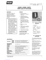
AR (Single Phase) Industrial Thermostat
2" O.D. Typ.
Capillary
2-21/32"
4-3/32"
2-21/32"
Bulb
Dia.
Length
(Refer to Specifications Table A)
NEMA-I Model
AR-LT
Moisture Resistant Model
3-3/8”
3-1/8”
5-7/8”
7/8”
7/8”
C
L
3/4” NPT Conduit Holes
7-1/16”
5-1/16”
4-7/16”
Temperature Approx. Capillary Maximum
NEMA I Range Dia. Length Length A.C. Rating
Model* (˚F) Style (In.) (In.) (Ft.) (Amps.)
AR-115 7
AR-115A 0–100˚F 5 0.375 4-3/8 2
AR-115C 12 10 Amp.
480 Vac
AR-214 7
4 0.250 5-5/32 30 Amp.
AR-214D 15 120-277 Vac
AR-215 7
60–250˚F 5 0.375 4
AR-215A 2
250VA
AR-219 7 120-277 Vac
9 0.188 10-3/4 (Pilot Duty)
AR-219D 15
AR-514 4 0.250 7-5/16 7
AR-515 7
200–550˚F 5 0.375 3-5/8
AR-515A 2
AR-519 7
9 0.188 11-1/2
AR-519D 15
AR-715 7
5 0.375 3-11/16
AR-715D 300–700˚F 15
AR-719 9 0.188 12 7
Sensing Bulb
Table A – Specifications
© 2010 Chromalox, Inc.
*Models equipped with Pilot Light are designated by the suffix “P” on the Model Number.
Models equipped with Knob Cover are designated by the suffix “KC” on the Model Number.
Models equipped with both a Pilot Light and a Knob Cov
er are designated by the suffix “PKC” on the
Model Number.
Models installed in a moisture resistant enclosure are designated by the suffix “LT” on the Model
Number.
Pilot Light nor Knob Cover available on LT models
.
Figure 1

GENERAL
MOUNTING
NOTICE: Type AR Thermostats are designed for temperature con-
trol service only. Because they do not fail safe, they should not be
used for temperature limiting duty.
The system designer is responsible for the safety of
this equipment and should install adequate back-up
controls and safety devices with their electric heat-
ing equipment. Where the consequences of failure
could result in personal injury or property damage,
back-up controls are essential.
Principle of Operation – Control action of these thermostats is pro-
vided through the principle of liquid volume change. With a variation
in temperature, the liquid in the sensing bulb expands or contracts,
causing a bellows to actuate the switching mechanism.
Enclosure – The control enclosure and cover assembly is of heavy-
gauge electrical grade plastic on NEMA-I models.
Moisture resistant (LT) models have enclosure and cover assembly
made of heavy gauge cast aluminum.
Power Supply –
FIRE/ELECTRIC SHOCK HAZARD. Use AC supply only.
Thermostat is not DC rated.
Control Range – The following temperature ranges are available:
0° to 100°F 200° to 550°F
60° to 250°F 300° to 700°F
Process Temperature Differential – is variation in controlled
process temperature between maximum, when thermostat turns OFF
and minimum, when thermostat turns ON. This spread in temperature
may be minimized by:
1. Making sure control is mounted to vertical surface (see Step 1,
Mounting section).
2. Avoiding excess heating capacity (oversized heaters).
3. Locating control sensing bulb in optimum position between heat
source and work.
In general, it is difficult to predict the actual operating differential
of a given process. Temperature differential may be as low as 4˚F for
low range controls to as high as 17˚F for higher range controls since
the differential is a percentage function of the dial range.
Packing Glands – If a sealed or leak-proof connection is required at
the point where the capillary enters the oven, tank, pipe or similar
equipment, an appropriate packing gland is available as an optional
part. (Model Numbers CCF-25A, CCF-25D or CCF-25E).
FIRE/EXPLOSION HAZARD. This thermostat is not
intended for use in hazardous atmospheres where
flammable vapors, gases, liquids or other com-
bustible atmospheres are present as defined in the
National Electrical Code. Failure to comply can result
in personal injury or property damage.
Note: Do not mount control where it will be subject to vibration,
shock, grease, dust, lint or corrosive vapors. Do not mount adjacent
to a large magnetic contactor, as vibration and shock will cause ther-
mostat to interact erratically - resulting in chattering of the contactor.
The air temperature in and around the control enclosure should be
kept as near to normal room temperature as possible...never above 150°F.
5"
5/16" Dia.
Mounting Lugs
5-7/8" Dia.
7/32" Dia.
(4)
Mounting Holes
3-7/8" Dia.
2-7/16" Dia.
(2)
NEMA-I Models LT Models
1”
Do Not
Bend or Kink
Crimped End
1/2”
Rod
Figure 3
(Sensing Bulb)
Figure 4
(Capillary Tube)
1. To facilitate adjusting and reading the thermostat, knob setting
must be mounted in a vertical position only.
2. Use sheet metal or wood screws through the mounting holes in
baseplate to mount control (see Figure 2).
3. For controlling platen or die temperatures, insert entire sensing
bulb into drilled holes selected for snug slip fit.
The longer, more sensitive Style 9 bulbs should be used for con-
trolling air temperatures or pipe line heating.
Note: If material in contact with bulb or capillary is corrosive, a pro-
tective well should be used. Protective wells are available as an
optional part. Check factory.
4. CAUTION –
A. Bending or deforming sensing bulb will alter control calibra-
tion – requiring recalibration after installation. See CALI-
BRATION section, page 3. If necessary, Style 9 bulbs can be
coiled to 1” I.D. (see Figure 3).
B. Do not kink capillary tube. The resulting constrictions in fluid
flow can destroy control function or broaden temperature dif-
ferential. Minimum capillary tube bending diameter is 1/2”
I.D. (see Figure 4).
C. Any deformations of bulb or capillary that result in leakage of
fluid from control renders control inoperative.
D. Avoid passing control capillary tube through zones whose
temperature is in excess of controlled process temperature.
Erratic control or destruction of control function may result.
ELECTRIC SHOCK HAZARD. Disconect all power to
heater before installing or servicing thermostat.
Failure to do so could result in personal injury or
property damage. Thermostat must be installed by a
qualified person in accordance with the National
Electrical Code, NFPA 70.
1. Electrical wiring must be installed in accordance with National
Electrical Codes or local codes.
CAUTION: Use copper conductors only.
NEMA-I Models –
A. Entrance for wiring is provided by two 1/2” conduit holes in
end of base plate.
B. If control is a “–KC” model (knob cover), remove knob cover
as in Figure 5.
C. Set thermostat knob to OFF position and then remove knob by
lifting knob from shaft (see Figure 6).
D. Loosen two screws from end of base plate and remove ther-
mostat cover (see Figure 7).
WIRING

WIRING
WIRING
Figure 5
Figure 11
Figure 12
Figure 6
Figure 7
Figure 8
Figure 9
1
2
3
4
Line
Single Phase
Load
Pilot
Light
Line
Load
Pilot Light
Single Phase
1
2
3
4
Load
1
2
3
4
Two Circuit
Line
Line
Load
Pilot Light
Load
Pilot
Light
1
2
3
4
Control
Voltage
Line
}
Pilot
Light
1
2
3
4
Line
Screwdriver
C
Adjusting
Set Screw
A
Adjusting
Shaft
B
Thermometer
Load (Tank, vat, die or platen)
Figure 13
Figure 14
Figure 15
Three Phase
And Single
Phase When
Load Exceeds
Rating of
Thermostat.
Three Phase
When Load
Does Not
Exceed
Rating of
Thermostat.
Figure 16 Figure 17
Figure 18
LT Models –
A. Entrance for wiring is provided by two 3/4” NPT conduit
holes in end of enclosure. Wiring to control enclosure should
be in moisture-resistant conduit.
B. Remove cover by removing four hexhead screwbolts (see
Figures 8 and 9).
2. Connect wires according to wiring diagrams (Figure 11 thru 15).
Note: Electrical connections should be made with generous loops
of wire – approximately 6” per lead.
3. Replace cover and tighten screws.
4. Replace dial knob and dial knob cover. (NEMA-I models only).
5. Note: If load amperage or voltage rating exceeds switch rating, a
contactor must be used (see Figure 14). Contactors are available
as an optional part.
ELECTRIC SHOCK HAZARD. Disconnect all power
before attempting to calibrate thermostat. Failure to
comply could result in personal injury.
These controls are factory calibrated to the range indicated on the
control adjustment knob.
If calibration is required, either one of two methods may be fol-
lowed:
A. If accurate measurement standards are not available, the ther-
mostat can be readily adjusted to a known temperature stan-
dard such as boiling water (212˚F) (see Figure 16).
B. With the aid of an accurate thermometer or other temperature
measuring device, recalibration may be performed within the
process as in Figure 17.
For either method, the following general calibration procedures
should be followed:
1. Remove knob cover, knob and thermostat housing as per instruc-
tions 3, 4 and 5 under WIRING.
2. Replace knob and turn to highest temperature setting.
3. Slowly turn knob and when controls click “off”, compare the dial
reading against the thermometer reading.
4. If they do not agree –
A. Set dial knob to thermometer temperature reading and pull off
knob.
B. While holding the adjusting shaft (B) tightly, turn small cen-
ter adjusting screw (A) with small screwdriver (C) until ther-
mostat clicks “off” (see Figure 18).
Note:
Always use extreme care not to damage the slot in the center
adjusting screw.
C. Each quarter turn of the screw will change the calibration
approximately 30˚F:
– Clockwise to decrease temperature
– Counterclockwise to increase temperature
D. Recheck calibration and repeat process if closer calibration is
required.

RENEWAL PARTS IDENTIFICATION
2
1
080-510512-001
213-018509-002
4
027-057548-001
Mounting Bracket
119-114623-003
Pack Gland
3
152-025660-004
Enclosure
NEMA-I Models
LT-Models
1347 HEIL QUAKER BLVD., LAVERGNE, TN 37086
Phone: (615) 793-3900 www.chromalox.com
Thermostat Thermostat
Model Sub-Assembly Cover Thermostat Base Knob
AR-115 300-048518-005 080-024763-001 015-013819-001 169-019605-002
AR-115A 300-048518-012 080-024763-001 015-013819-001 169-019605-002
AR-115C 300-048518-019 080-024763-001 015-013819-001 169-019605-002
AR-214 300-048518-001 080-024763-001 015-013819-001 169-019604-001
AR-214D 300-048518-026 080-024763-001 015-013819-001 169-019604-001
AR-215 300-048518-010 080-024763-001 015-013819-001 169-019604-001
AR-215A 300-048518-013 080-024763-001 015-013819-001 169-019604-001
AR-219 300-048518-002 080-024763-001 015-013819-001 169-019604-001
AR-219D 300-048518-022 080-024763-001 015-013819-001 169-019604-001
AR-514 300-048518-003 080-024763-001 015-013819-001 169-019604-002
AR-515 300-048518-011 080-024763-001 015-013819-001 169-019604-002
AR-515A 300-048518-014 080-024763-001 015-013819-001 169-019604-002
AR-519 300-048518-004 080-024763-001 015-013819-001 169-019604-002
AR-519D 300-048518-027 080-024763-001 015-013819-001 169-019604-002
AR-715 300-048518-006 080-024763-001 015-013819-001 169-019605-001
AR-715D 300-048518-029 080-024763-001 015-013819-001 169-019605-001
AR-719 300-048518-007 080-024763-001 015-013819-001 169-019605-001
1 4
32
Limited Warranty:
Please refer to the Chromalox limited warranty applicable to this product at
http://www.chromalox.com/customer -service/policies/termsofsale.aspx.
/