Page is loading ...

Item #s 3600 & 4200
POST MOUNT
FOR OUTDOOR USE ONLY
7” Water Column for Natural Gas
11” Water Column for Liquid Propane
Maximum Pressure 0.5 PSI
THE LAMP HEAD MUST BE INSTALLED TO CONFORM WITH LOCAL CODES, OR IN ABSENCE OF
LOCAL CODES, WITH THE NATIONAL FUEL GAS CODE ANSI Z223.1 – LATEST EDITION,
CAN1-B149.1 or CAN1-B149.2
THE MINIMUM CLEARANCE FROM COMBUSTIBLE CONSTRUCTION IS 12” TOP BY 6” SIDE.
POST INSTALLATION (for standard burial steel or aluminum posts):
1. Obtain a 3” outside diameter post with notch for valve access at top.
2. Install ¼”OD refrigeration type copper tubing inside post with ¼” flare nuts at each end.
Tubing should be coiled 2½ times at top and protrude approximately 5” through hole at bottom of post.
3. If supplied, insert ladder rest through ladder rest holes and attach ornamental balls to each end.
4. Dig a hole 21” deep x 12” wide.
5. If using ladder rest, position post with ladder rest facing desired direction.
6. Attach the ¼” flare nut at the bottom of the post to the gas supply and tighten the flare nut clockwise.
No sealants are necessary.
7. Secure post in plumb position and pour concrete around post to just below the level of the line access hole.
8. If using a cast pedestal base, remove the (4) screws and nuts from each side and place each piece of the base around the
bottom of the post. Secure it together using the (4) screws and nuts. Push the base approximately 1”–2” into the ground and
secure in place using the back fill from the post. If the base is not secured in the ground, the freeze and thaw of the ground
can force the base to rise and fall, causing the finish of the post to scratch.
LAMP INSTALLATION:
1. Feed the gas feedline through the yoke and attach the ¼” flare nut at the top of the post to the connector valve inside the lamp
collar, below the burner. To slide the burner out for connection, loosen the front setscrew beneath the bottom fitter.
2. Lower lamp head onto post and tighten set screw(s) in the bottom of yoke so lamp is well secured to post.
3. Be certain the lamp valve is in the OFF position (3 o’clock position) before turning on the main gas supply.
4. Leaving lamp valve in OFF position, turn on main gas supply and check all connections for leaks using a soapy solution.
NEVER USE AN OPEN FLAME TO CHECK FOR GAS LEAKS! Tighten any leaky connections and recheck for leaks.
5. If using mantles, install mantles per instructions on packaging before turning lamp valve on.
If using open flame, turn lamp valve ON (12 o’clock position) with a flathead screwdriver and slowly move flame toward
burner tip until it ignites.
6. For gas mantle, leave valve full open. For open flame, adjust flame to ½ - ¾ open.
7. Proceed to Globe & Dome Installation Instructions.
FOR YOUR SAFETY
If you smell gas:
1. Shut off gas to the appliance.
2. Extinguish any open flame.
3. If odor continues, immediately
call gas supplier.
FOR YOUR SAFETY
Do not store or use gasoline or
other flammable vapors and
liquids in the vicinity of this or
any other gas appliance.
INSTALLER: Please leave instructions with the appliance for the consumer to retain for future reference
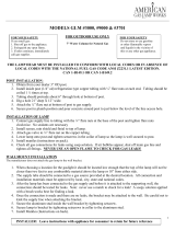
VENTILATOR
DOME
BOTTOM FITTER
ASSEMBLY
YOKE SOCKET
ASSEMBLY
GLOBE
INSIDE STEEL
SUPPORT ROD
CROWN ASSEMBLY
SIDE ARMS

GLOBE & DOME INSTALLATION:
1. Open ring assembly and place globe down through until it rests on the inner ring assembly. Be careful not to touch burning
mantles. If the globe is not resting on the bottom fitter, loosen the (2) back setscrews beneath the bottom fitter and slide it up
until the globe sits secure. Tighten setscrews to secure bottom fitter. DO NOT loosen the single front setscrew while the
burner is lit; this one holds the burner in place.
2. Close the outer ring assembly and secure with latch.
3. Place dome on top of ring assembly and tighten knurled screws to hold dome in place.
4. Place ventilator assembly on top of dome and tighten knurled screws to hold ventilator in place.
MAINTENANCE INSTRUCTIONS:
No combustible material, gasoline, or other flammable vapors or liquids should be stored near lamp. Nothing should
obstruct the flow of combustion or ventilation air. Occasionally, the glass will need to be cleaned with household glass
cleaner and gas mantles (if using) should be visually checked. Replace mantles if necessary. Gas lamp parts and mantles
are available from:
AMERICAN GAS LAMP WORKS LLC
101 Hoeveler Street
Springdale, PA 15144
(Phone) 724-274-7131 or (Toll Free) 855-427-5483
www.AmericanGasLamp.com
CAUTION
TURN GAS SUPPLY OFF AND WAIT FOR LAMP TO COOL BEFORE PERFORMING ANY REPAIRS.
REMOVE AND CLEAN GLASS AND REPLACE MANTLES (IF APPLICABLE) AS NECESSARY.
INVERTED MANTLE CHANGING/LIGHTING INSTRUCTIONS:
1. Insert flathead screwdriver through the access hole in the lower collar of the lamp. Turn screwdriver to the right
(to the 3:00 position) to turn off the gas.
2. Let the glass cool approximately 15-20 minutes.
3. Gently remove the glass by pushing the panel up with your fingers, then pull backward (toward you) and lower
the panel from the bottom of the frame.
4. Carefully remove the old mantles from the ceramic burner tips by lifting the ceramic rings up, give ¼ turn, and
pull down. Discard the old mantles and any debris lying in the bottom of the lamp.
5. Remove the new mantles from the packaging and install onto the ceramic burner tips by lifting the ceramic rings
up and giving ¼ turn. *If using soft mantles, gently pull down to shape the mantles.*
6. With the gas still OFF, light the mantles by applying direct flame to the mantles; this is necessary to burn off the
protective coating.
7. Once the protective coating burns off and the light goes out, insert a flathead screwdriver through the access hole
in the lower collar of the lamp. Apply direct flame to the mantles with a lighter or a match – be sure not to touch
the mantles, as they are very fragile – and slowly turn the screwdriver to the left (towards the 12:00 position).
8. Once lit, turn the gas on full (to the 12:00 position) and replace the glass panel.
OPEN FLAME BURNER LIGHTING INSTRUCTIONS:
1. Insert flathead screwdriver through the access hole in the lower collar of the lamp. Turn screwdriver to the right
(to the 3:00 position) to turn off the gas.
2. Let the glass cool approximately 15-20 minutes.
3. Gently remove the glass by pushing the panel up with your fingers, then pull backward (toward you) and lower
the panel from the bottom of the frame.
4. Turn lamp valve ON (to the 12:00 position) with a flathead screwdriver and slowly move flame toward burner tip
until it ignites.
5. Once lit, replace the glass panel and adjust flame to ½ - ¾ open by SLOWLY turning the lamp valve towards the
3:00 position. Turning the valve too fast or too far can case the flame to extinguish.
*For additional assistance, please contact our Customer Support Team at 724-274-7131 or
/