
ro-solutions.com
Design Guide
Pressure safety valve in a
seawater RO system
ro-solutions.com

Design Guide Pressure Safety Valve in a seawater RO system
2
180R9371 | 521B1399 | DKCFN.PI.000.2D.02 | 07.2016
Table of Contents Table of Contents
1. Introduction ............................................................................3
2. Summary ...............................................................................3
3. Terms and denitions ...................................................................3
3.1 Risk consideration according to PED ISO 4126-9:2008(E) ..................................4
4. Pressure limitation ......................................................................5
4.1 What is a Pressure Safety Valve (PSV) ....................................................5
4.2 What is a Pressure Relief Valve (PRV) .....................................................5
5. Input to the risk analysis.................................................................6
5.1 How does a pump make pressure?.......................................................6
5.2.1 Max. discharge pressure from a Centrifugal pump .......................................6
5.2.2 Max. discharge pressure from a Positive Displacement pump.............................6
5.3 Design considerations...................................................................6
5.3.1 Where to position the PRV or PSV........................................................6
5.4 Examples of risk considerations..........................................................7
6. Disclaimer ..............................................................................7

Design Guide Pressure Safety Valve in a seawater RO system
3
180R9371 | 521B1399 | DKCFN.PI.000.2D.02 | 07.2016
1. Introduction
The information’s in this document are
based on PED 97/23/EC and ISO 4126
“Safety devices for protection against
excessive pressure”. ISO 4126 is conrming
to Essential Requirements of the new Ap-
proach Directive 97/23/EC (PED)
This guideline is giving input to the risk
analysis and guiding how to size a Pressure
Safety Valve and where to place this valve
in a Sea Water Reverse Osmosis (SWRO)
system.
2. Summary
The Pressure Equipment Directive 97/23/EC
(PED) of the EU sets out the standards for the
design and manufacture of pressure equipment
(“pressure equipment” means pressure vessels,
piping, safety valves and other components
and assemblies subject to pressure loading). It
has been mandatory throughout the European
Union since 30 May 2002.
The PED enacted in the UK as the Pressure Equip-
ment Regulations (PER).
The system designer is responsibility to
design the equipment according to the local
regulations where the equipment is running.
Local regulations according to Pressure
equipment and machinery protection must be
followed.
According to PED 97-23-EC a risk assessment
must be made to identify and evaluate hazards
which apply to his equipment on account of
pressure.
Where, under reasonable foreseeable conditions,
the allowable limits could be exceeded, the pres-
sure equipment must be tted with, or provision
made for tting of, suitable protective devises.
Pressure limiting devices must be so designed
that the pressure will not permanently exceed
the maximum allowable working pressure (Ps);
however a short duration the momentary pres-
sure surge must be kept to 10% of Ps for pressure
vessels and max 17% of Ps for the pump alone.
Discharge pressure on the pump is generated
only by the restrictions in the pipelines, valves
and membranes.
The pump can build up pressure that will exceed
the mechanical strength of the membrane ves-
sels, pipes and other accessories.
The pressure rise can be fast and may exceed the
response time for electrical safety equipment,
like pressure switch and control loop.
3. Terms and denitions
Safety device: Device that serves as the ultimate
protection to ensure that the maximum allowable
accumulated pressure is not exceeded. Example
is a safety valve or bursting disc.
Harm: Harm is the physical injury or damage to
health of people, or damage to property or to the
environment.
Hazard: Potential source of harm
Risk: Combination of the probability of occur-
rence of harm and the severity of that harm.*)
Risk analysis: Use of available information to
identify hazards and to estimate the risk. *)
Risk evaluation: Judgement on the basis of risk
analysis as to whether a tolerable risk has been
achieved. *)
Risk assessment: Overall process of risk analysis
and risk evaluation. *)
Maximum allowable pressure (Ps): Maximum
pressure for which the equipment is designed, as
specied by the manufacture.
Accumulated pressure: Pressure in the equip-
ment to be protected which can exceed maxi-
mum allowable pressure for a short duration
during the operation of safety devices.
Maximum allowable accumulated pressure
Ps, accum: Value of the accumulated pressure in
the equipment being protected.
Redundancy: Provision of more than one device
or system such that the necessary function will
still be provided in case of failure of one or more
of these devices.
*) See ISO/IEC Guide 51

Design Guide Pressure Safety Valve in a seawater RO system
4
180R9371 | 521B1399 | DKCFN.PI.000.2D.02 | 07.2016
3.1 Risk consideration according to
PED ISO 4126-9:2008(E)
All service conditions shall be considered when
selecting the most appropriate safety concept,
in order to ensure safe operation of the pressure
equipment. This requires a realistic assessment of
risk by means of risk analysis and risk evaluation.
Risk analysis involves, for example:
• Determination of boundaries of the
pressure equipment, concluding:
- Maximum quantity of uid to be disharged
- Intended use
- Reasonably foreseeable misuse
- Inuences of sizing and ow of the safety
device on operational reliability and
performance of the safety system
• Identication of potential hazards and esti-
mation of the risk.
In particular, the risk analysis shall take in consid-
eration the following:
• Equipment connected together by piping of
adequate capacity, which is free from poten-
tial blockage and does not contain any valve
that can isolate any part, may be considered
as a system of pressurized components for
application of pressure relief.
• Where a component failure during
operation is forseen and would cause the
pressure of uid in the vessel to exceed the
maximum allowable pressure, the pressure
equipment shall be protected by means
of at least one safety device of adequate
capacity of safety device(s).
Where, under reasonably foreseeable service
conditions, the internal pressure can exceed
the maximum allowable pressure, the pressure
equipment shall be protected by means of at
least one safety device of adequate capacity and
capability.
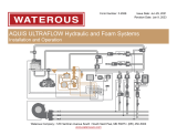
A safety device is the nal element to protect
pressure equipment from exceeding its allow-
able limits. Regulating and/or monitoring devices
are not ultimate safety devices in the meaning of
ISO 4126-9. They become active in advance of an
ultimate safety device (see gure below)
50
60
70
80
90
100
110
120
Pressure(%)
Time
Diagramoftypicalsystemrelationship
Maximumallowablepressure(Ps)
Maximumallowableaccumulatedpressure(P
s,accum)
1
4
2
3
Nocontinuousoperationinthiszone
1 Reaction of regulating control system
2 Reaction of monitoring system
3 Reaction of safety system
4 Normal operating range

Design Guide Pressure Safety Valve in a seawater RO system
5
180R9371 | 521B1399 | DKCFN.PI.000.2D.02 | 07.2016
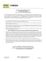
0
10
20
30
40
50
60
70
80
90
100
110
120
0 20 40 60 80 100 120
Pressure(%)
Flow(%)
PSVflowcurve
PSV
Maximumallowablepressure(Ps)
Maximumallowableaccumulatedpressure(P
s,accum)
MaximumSet
p
ressure
Maxdischargecapacity
4. Pressure limitation
• Safety devices shall have a set pressure not
exceeding the maximum allowable pressure
(Ps)
• If capacity is provided by more than one
safety device, only one of the devices needs
to be set at a pressure not exceeding (Ps).
The other device(s) may be set at a pressure
not more than 5% in excess of (Ps).
4.1 What is a Pressure Safety Valve (PSV)
• The safety device(s) shall be sized to have
the required discharge capacity at a pres-
sure not higher than maximum allowable
accumulated pressure (Ps, accum).
A PSV is a valve which automatically, without
the assistance of any energy other than that of
the uid concerned, discharges a quantity of
the uid so as to prevent a predetermined safe
pressure being exceeded, and which is designed
to re-close and prevent further ow of uid after
normal pressure conditions of service have been
restored.
The allowable tolerances on the operating
characteristics are as follows:
• Set pressure ± 3% of set pressure.
• Overpressure: The value stated by the
manufacturer but not exceeding 10% of set
pressure
• Blowdown: Not greater than the value
stated by the manufacture and minimum
2,5% of set pressure
4.2 What is a Pressure Relief Valve (PRV)
In contrast to a safety valve a Pressure Relief
Valve is designed to guarantee trouble-free op-
eration of a pressurized system or a component.
The job of the relief valve is mainly:
• Protect the pressurized system or a compo-
nent.
• Discharge excessive ow rates within certain
pressure limits.
• Protection of the downstream PSV. If both a
PRV and PSV are installed, the PRV operation
range must be below the set pressure of the
PSV
The function of a PRV is equal to the function
of the PSV – BUT no demands are made on the
opening and blowdown characteristics

Design Guide Pressure Safety Valve in a seawater RO system
6
180R9371 | 521B1399 | DKCFN.PI.000.2D.02 | 07.2016
5. Input to the risk
analysis
5.1 How does a pump make pressure?
Whatever a pump is of type positive displace-
ment (PD) or a rotary Centrifugal (CF), the pump
can only build up pressure corresponding to the
total hydraulic resistance in the downstream line
including pipelines, valves, and membranes etc.
If there is no hydraulic resistance, the pump can-
not create any pressure.
5.2.1 Max. discharge pressure from a
Centrifugal pump
Maximum hydraulic discharge pressure from a CF
pump is often called “shut-o pressure” or “dead-
end pressure”. This pressure is well known from
the pump curve on a specic pump. Therefore a
CF pump may be started up against a dead-end
without risk for over-pressurizing the system.
5.2.2 Max. discharge pressure from a Positive
Displacement pump
Maximum hydraulic discharge pressure from a
PD pump is unpredictable. If the motor driving
the PD pump can supply sucient power the
pump will raise the pressure until ALL ow from
the pump can escape the pump. Alternative the
pump will break internally or the weakest com-
ponent in the pump discharge line will break.
The pressure rise can be fast and may exceed
the response time for electrical safety equip-
ment, like pressure switch and control loop.
5.3 Design considerations
5.3.1 Where to position the PRV or PSV
The inline NRV can be assembled with wrong
ow direction. The PRV or PSV must be placed
between the pump and the NRV.
The anged NRV on APP cannot be assembled
with wrong ow direction.
The PRV or PSV must be placed between the
pump and the rst valve or component that can
generate to high pressure.
Always follow the instalation guideline from the
PSV or PRV manufacturer.
Permeate
Concentrate
PI
Permeate
Concentrate
PI
The inline NRV can be assembled with wrong
ow direction. The PRV or PSV must be placed
between the pump and the NRV.
Permeate
Concentrate
PI

Design Guide Pressure Safety Valve in a seawater RO system
7
180R9371 | 521B1399 | DKCFN.PI.000.2D.02 | 07.2016
5.4 Examples of risk considerations
1. A valve that can be closed or partly closed in
the pump discharge line may be a high risk
component together with a PD pump.
- If the valve by purpose or by accident
can be closed faster than the response
time for electrical monitoring system,
the PRV or PSV must be able to take full
ow from the pump.
- If the valve by purpose or by accident
can NOT be closed faster than the
response time for electrical monitoring
system, the PRV or PSV must be able to
take excess ow that eventually causes
a pressure peak.
- A permeate back-pressure controlvalve
can raise the pressure both on LP
permeate line and the HP line.
2. The ow on a PD pump is proportional to
the speed. If the PD pump is started by
ramping up the spe ed from 0 to s et-po int
over a period of time, the ow will also wary
from zero to set-ow over the same time
period. If the Pump is started up against a
dead-end the pressure will rises rapidly but
the ow will be small. With respect to the
response time of the electrical monitoring
system, the PSV must be able to take ow
that eventually causes a pressure peak.
Example:
- Total response time for electrical
monitoring system to cut main power
to electrical motor is 1 seconds.
- A 78 m³/h pump is ramping up from 0
to 1500 rpm over 20 seconds.
- After 1 second the pump is giving 3.9
m³/h.
- The PRV or PSV must be able to take a
minimum of 3.9 m³/h.
3. If the pump is started direct online (DOL)
against a closed valve the pressure will rise
rapidly and exceed the response time for
electrical monitoring system, the PRV or PSV
must be able to take full ow.
4. The membrane in a RO plant is generating
the main hydraulic pressure in the HP line.
Fouling/ Scaling over time come slowly and
the pressure rise is slower than the response
time for electrical monitoring system. If the
response time of the electrical system is not
fast enough the PRV or PSV must be able to
take excess ow that eventually causes a
pressure peak. PRV or PSV ow capacity can
be calculated at max allowable working
pressure.
Q
PSV
= Q
HP-Pump
– Q
Concentrate
– Q
Membrane
5. In a RO plant with an Isobaric energy
Recovery Device (ERD) all ow from the HP
pump will escape through the RO
membrane even if the ERD is stopped. With
the ERD stopped the membranes will run
with a 100% recovery rate and the
membrane fouling will cause a pressure
raise that may not exceed the response time
of the electrical monitoring system.
6. In a RO plant with a backpressure valve on
the HP concentrate line a part of the ow
from the HP pump will escape through
the RO membrane the rest goes through
the backpressure valve. With the
backpressure valve totally closed the
membranes will run with a 100% recovery
rate and the membrane may not be able to
take all ow from the HP pump. The
pressure raise may exceed the response
time of the electrical monitoring system and
the PRV or PSV must be able to take the
same amount of ow as the backpressure
ow.
7. As the electrical monitoring system can fail
a redundancy electrical monitoring system
is necessary.
6. Disclaimer
Although the information and recommendations
in this document (electronic or printed form) are
presented in good faith and believed to be cor-
rect, Danfoss A/S, Danfoss High Pressure Pumps
makes no representations or warranties as to the
completeness or accuracy of the information.
Information is supplied upon the condition
that the persons receiving same will make their
own determination as to its suitability for their
purposes prior to use. In no event will Danfoss
A/S, Danfoss High Pressure Pumps be responsible
for damages of any nature whatsoever resulting
from the use of or reliance upon information
from this document or the products to which the
information refers.
Danfoss A/S, Danfoss High Pressure Pumps does
not warrant the accuracy or timeliness of the
materials in the document and has no liability for
any errors or omissions in the materials.
THIS “DOCUMENT” IS PROVIDED ON AN “AS
IS”BASIS. NO REPRESENTATIONS OR WARRANTIES,
EITHER EXPRESSED OR IMPLIED, OF MERCHANT-
ABILITY, FITNESS FOR A PARTICULAR PURPOSE OR
OF ANY OTHER NATURE ARE MADE HEREUNDER
WITH RESPECT TO INFORMATION OR THE PROD-
UCTS TO WHICH INFORMATION REFERS

© Danfoss | DCS (im) | 2016.07
180R9371 | 521B1399 | DKCFN.PI.000.2D.02 | 8
Danfoss can accept no responsibility for possible errors in catalogues, brochures and other printed material. Danfoss reserves the right to alter its products without notice.
This also applies to products already on order provided that such alterations can be made without subsequential changes being necessary in specications already agreed.
All trademarks in this material are property of the respective companies. Danfoss and the Danfoss logotype are trademarks of Danfoss A/S. All rights reserved.
Danfoss A/S
High Pressure Pumps
DK-6430 Nordborg
Denmark
-
 1
1
-
 2
2
-
 3
3
-
 4
4
-
 5
5
-
 6
6
-
 7
7
-
 8
8


Ask a question and I''ll find the answer in the document
Finding information in a document is now easier with AI
Related papers
-
Danfoss NRV CO2 Installation guide
-
-
-
Danfoss 180F7021 User guide
-
Danfoss 180F7021 User guide
-
-
-
Danfoss 180B3007 Installation guide
-
Danfoss 180B3211 Installation guide
-
Other documents
-
OKI C931e User guide
-
ClearOne ACCUMIC 800-157-001 User manual
-
 Polytec PSV-I-570 Operating Instructions Manual
-
 Waterous F-2928 HYDRAULICS Operating instructions
-
LG HN1616T User manual
-
LG R410A Integrated tank type Installation guide
-
Pioneer PRV-9200 User manual
-
CRYSTAL XP2i Operating instructions
-
 Hubbell Power Systems Uni-Grip Deadends Installation guide
-
Rosemount BINOS E Analyzer-3rd Ed. User manual


