Trane INTELLIPAK SEHG-C90 User manual
- Category
- Heat pumps
- Type
- User manual

Trane has a policy of continuous product and product data improvement and
reserves the right to change design and specifications without notice. Only
qualified technicians should perform the installation and servicing of
equipment referred to in this publication.
Installation RT-SVX10C-EN
Operation
Maintenance
Library Service Literature
Product Section Unitary
Product Rooftop Air Conditioning (Comm. SZ, 20 - 130 Tons)
Model SAH_, SEH_, SFH_, SLH_, SSH_, SXH_
Literature Type Installation/Operation/Maintenance
Sequence 10C
Date January 2005
File No. SV-UN-RT-RT-SVX10C-EN-01-05
Supersedes RT-SVX10C-EN 11/04
© 2004 American Standard Inc. All rights reserved
INTELLIPAK
™™
™™
™
Commercial Single-Zone Rooftop Air
Conditioners with CV or VAV Controls
- Units whose model numbers
have a "1" in digit 20 are certified
by Underwriters Labortory.
- Units whose model numbers
have a "2" in digit 20 are certified
by the Canadian Standards
Association (CSA).
Models
"5" and later Design Sequence
SAHF -C20, -C25, -C30, -C40, -C50, -C55, -C60, -C70, -C75
SEHF -C20, -C25, -C30, -C40, -C50, -C55, -C60, -C70, -C75
SFHF -C20, -C25, -C30, -C40, -C50, -C55, -C60, -C70, -C75
SLHF -C20, -C25, -C30, -C40, -C50, -C55, -C60, -C70, -C75
SSHF -C20, -C25, -C30, -C40, -C50, -C55, -C60, -C70, -C75
SXHF -C20, -C25, -C30, -C40, -C50, -C55, -C60, -C70, -C75
"X" and later Design Sequence
SXHG -C90, -D11, -D12, -D13 SEHG -C90, -D11, -D12, -D13
SFHG -C90, -D11, -D12, -D13 SLHG -C90, -D11, -D12, -D13
SSHG -C90, -D11, -D12, -D13
With 3-D
TM
Scroll Compressors
®

2
About The Manual
Note: This document is customer property and
must be retained by the unit's owner for use by
maintenance personnel.
Literature Change History
RT-SVX10C-EN (November 2004)
Re-issue of manual for minor corrections to Connection
Sizes Table 3-5; provides specific installation, operation
and maintenance instructions for S_HF with “6” and
later design sequence and S_HG with “Y” and later de-
sign sequence with constant volume (CV) or variable air
volume (VAV) controls.
RT-SVX10C-EN (October 2004)
Re-issue of manual for minor corrections to warranty and
updated sensor numbers (BAYSENS019, 20); provides
specific installation, operation and maintenance instruc-
tions for S_HF with “6” and later design sequence and
S_HG with “Y” and later design sequence with constant
volume (CV) or variable air volume (VAV) controls.
RT-SVX10C-EN (July 2004)
Re-issue of manual for minor WARNING and CAUTIONS
and Warranty information updates; provides specific in-
stallation, operation and maintenance instructions for
S_HF with “6” and later design sequence and S_HG
with “Y” and later design sequence with constant volume
(CV) or variable air volume (VAV) controls.
RT-SVX10C-EN (December 2003)
Re-issue of manual for minor changes to programming
parameters; provides specific installation, operation and
maintenance instructions for S_HF with “6” and later de-
sign sequence and S_HG with “Y” and later design se-
quence with constant volume (CV) or variable air volume
(VAV) controls.
RT-SVX10B-EN (October 2003)
Updated issue of this manual; provides specific installation,
operation and maintenance instructions for S_HF with “6”
and later design sequence and S_HG with “Y” and later de-
sign sequence with constant volume (CV) or variable air vol-
ume (VAV) controls.
RT-SVX10A-EN (May 2003)
Updated issue of this manual; provides specific installation,
operation and maintenance instructions for S_HF with “5”
and later design sequence and S_HG with “X” and later de-
sign sequence with constant volume (CV) or variable air vol-
ume (VAV) controls.
SXH_-IOM-9 (November 2002)
Re-issue of manual for minor clarity issues; provides specific
installation, operation and maintenance instructions for “3”
and later design sequence on S_HF units and "W" and later
design sequence on S_HG units with constant volume (CV)
or variable air volume (VAV) controls.
SXH_-IOM-9 (June 2002)
Original issue of manual; provides specific installation, op-
eration and maintenance instructions for “3” and later design
sequence on S_HF units and "W" and later design sequence
on S_HG units with constant volume (CV) or variable air vol-
ume (VAV) controls.
These units are equipped with electronic Unit Control Mod-
ules (UCM) which provides operating functions that are sig-
nificantly different than conventional units. Refer to the "Start-
Up" and "Test Mode" procedures within this Installation, Op-
eration, & Maintenance manual and the latest edition of the
appropriate programming manual for CV or VAV applications
before attempting to operate or service this equipment.
Note: The procedures discussed in this manual
should only be performed by qualified, experienced
HVAC technicians.
Overview of Manual
This booklet describes proper installation, start-up, opera-
tion, and maintenance procedures for 20 through 130 Ton
rooftop air conditioners designed for Constant Volume (CV)
and Variable Air Volume (VAV) applications. By carefully re-
viewing the information within this manual and following the
instructions, the risk of improper operation and/or component
damage will be minimized.
Note: One copy of the appropriate service literature
ships inside the control panel of each unit.
It is important that periodic maintenance be performed to help
assure trouble free operation. Should equipment failure occur,
contact a qualified service organization with qualified, experi-
enced HVAC technicians to properly diagnose and repair this
equipment.
Note: Do Not release refrigerant to the atmosphere!
If adding or removing refrigerant is required, the service
technician must comply with all federal, state, and local
laws.

3
Table of Contents
Section One
About The Manual ...............................................................2
Literature Change History................................................2
Overview of Manual .........................................................2
Section Two
General Information.............................................................4
Model Number Description ..............................................4
Hazard Identification ........................................................6
Commonly Used Acronyms .............................................6
Unit Description................................................................6
Input Devices & System Functions..................................8
Constant Volume & Variable Air Volume Units ................8
Constant Volume (CV) Units..........................................10
Variable Air Volume (VAV) Units ....................................11
Space Temperature Averaging .......................................12
Unit Control Modules (UCM) ..........................................12
Section Three
Installation..........................................................................14
Unit Inspection ...............................................................14
Storage...........................................................................14
Unit Clearances .............................................................14
Unit Dimensions & Weight Information..........................14
Roof Curb and Ductwork ...............................................22
Pitch Pocket Location ....................................................23
Unit Rigging & Placement..............................................23
General Unit Requirements ...........................................25
Main Electrical Power Requirements.............................25
Field Installed Control Wiring.........................................25
Requirements for Electric Heat Units ............................25
Requirements for Gas Heat ...........................................25
Requirements for Hot Water Heat (SLH_) .....................25
Requirements for Steam Heat (SSH_) ..........................26
O/A Pressure Sensor and Tubing Installation ...............26
Condensate Drain Connection.......................................27
Shipping Fasteners ........................................................27
O/A Sensor & Tubing Installation...................................31
Units with Statitrac™; ....................................................31
Gas Heat Units (SFH_) ..................................................32
Connecting the Gas Supply Line to the Furnace
Gas Train........................................................................32
Flue Assembly Installation .............................................34
Hot Water Heat Units (SLH_) ........................................34
Steam Heat Units (SSH_)..............................................35
Disconnect Switch External Handle...............................38
Electric Heat Units (SEH_) ............................................38
Main Unit Power Wiring .................................................38
Disconnect Switch Sizing (DSS)....................................44
Field Installed Control Wiring.........................................45
Controls using 24 VAC...................................................45
Controls using DC Analog Input/Outputs.......................45
Constant Volume System Controls................................45
Variable Air Volume System Controls ............................46
Constant Volume or Variable Air Volume System
Controls ..........................................................................46
Section Four
Unit Start-Up ......................................................................55
Cooling Sequence of Operation ....................................55
Gas Heating Sequence of Operation.............................56
Fenwal Ignition System..................................................56
Honeywell Ignition System.............................................56
Modulating Gas Sequence of Operation .......................57
Flame Failure .................................................................57
Electric Heat Sequence of Operation ............................58
Wet Heat Sequence of Operation..................................58
Electrical Phasing ..........................................................59
Voltage Supply and Voltage Imbalance .........................60
Service Test Guide for Component Operation...............61
Verifying Proper Fan Rotation .......................................63
If all of the fans are rotating backwards;........................63
System Airflow Measurements ......................................63
Constant Volume Systems.............................................63
Variable Air Volume Systems.........................................65
Exhaust Airflow Measurement .......................................66
Tra q
TM
Sensor Airflow Measurement............................ 66
Economizer Damper Adjustment................................. 80
Compressor Start-Up ................................................... 82
Compressor Operational Sounds ................................ 83
Thermostatic Expansion Valves................................... 93
Charging by Subcooling .............................................. 93
Low Ambient Dampers................................................. 93
Electric, Steam and Hot Water Start-Up ...................... 94
Gas Furnace Start-Up .................................................. 94
Two Stage Gas Furnace ............................................... 95
Full Modulating Gas Furnace....................................... 97
Limited Modulating Gas Furnace ................................ 98
Final Unit Checkout...................................................... 99
Section Five
Service & Maintenance....................................................100
Fan Belt Adjustment.....................................................104
Scroll Compressor Replacement.................................105
VFD Programming Parameters ...................................106
Monthly Maintenance...................................................107
Filters............................................................................107
Cooling Season............................................................107
Heating Season............................................................108
Coil Cleaning................................................................108
Final Process .............................................................. 109
Index ........................................................................... 111
Warranty ..................................................................... 114

4
General Information
Model Number Description
All products are identified by a multiple character model
number listed on the unit nameplate. An explanation of the
alphanumeric identification code is provided below. Its use
can define the unit's specific components, type of applica-
tion, i.e. CV or VAV, for a particular unit.
When ordering replacement parts or requesting service, be
sure to refer to the specific model number, serial number,
and DL number (if applicable) stamped on the unit name-
plate.
Sam
p
le Model No.: S X H F - C20 4 0 A 1 0 A 1 5 B 1 D 0 1 A,R,L,etc.
Digit No.: 1 2 3 4 5,6,7 8 9 10 11 12 13 14 15 16 17 18 19 20 21+
Digit 1 - Unit Type Digit 10 - Design Sequence Digit 17 - System Control
S = Self-Contained 3 = Disconnect Redesign 1 = CV Control (Zone Control)
Note: Sequence may be any letter
2 = VAV-(
S/
A Temp
C
ontrol
Di
g
it 2 - Unit Function A thru Z, or an
y
di
g
it 1 thru 9.
without Inlet Guide Vanes)
A = DX Cooling, No Heat 3 = VAV-(S/A Temp Control
E = DX
C
ooling, Electric Heat
Digit 11 - Exhaust Option
with Inlet
G
uide Vanes)
F = DX Cooling, Natural Gas Heat 0 = None 4 = Space Pressure Control with Exhaust VFD
L = DX Cooling, Hot Water Heat 1 = Barometric without Bypass
S = DX Cooling, Steam Heat 2 = 100% - 1.5 HP* 5 = Space Pressure Control with Exhaus t VFD
X = DX Cooling, Extended Casings 3 = 100% - 3 HP* and Bypass
# = DX Cooling, Propane Gas Heat 4 = 100% - 5 HP* 6 = VAV Supply Air Temperature Control
5 = 100% - 7.5 HP* with VFD w/o Bypass
Di
g
it 3 - Unit Airflow
6 = 100% - 10 HP* 7 = VAV Supply Air Temperature Control
H = Single-Zone 7 = 100% - 15 HP* with VFD and Bypass
8 = 100% - 20 HP* 8 = Supply and Exhaust Fan with VFD
Di
g
it 4 - Develo
p
ment Se
q
uence
A = 50% - 1.5 HP without Bypass
F = Sixth B = 50% - 3 HP 9 = Supply and Exhaust Fan with VFD
C = 50% - 5 HP and Bypass
Di
g
its 5, 6, 7 - Nominal Ca
p
acit
y
D = 50% - 7.5 HP
C
20 = 20 Tons
C
55 = 55 Tons E = 100% - 1.5 HP**
Di
g
it 18 - Accessor
y
Panel
C25 = 25 Tons C60 = 60 Tons F = 100% - 3 HP** 0 = None
C30 = 30 Tons C70 = 70 Tons G = 100% - 5 HP** A = BAYSENS008*
C40 = 40 Tons C75 = 75 Tons H = 100% - 7.5 HP** B = BAYSENS010*
C50 = 50 Tons J = 100% - 10 HP** C = BAYSENS013*
K = 100% - 15 HP** D = BAYSENS014*
Digit 8 - Power Supply
L = 100% - 20 HP** E = BAY
S
EN
S
019*
4 = 460/60/3 XL # = 50% w/ Statitrac F = BAYSENS020*
5 = 575/60/3 XL * w/Statitrac G = BAYSENS021*
E = 200/60/3 XL ** w/o Statitrac (CV only)
F = 230/60/3 XL
Di
g
it 19 - Ambient Control
Note: SEHF units
(
unit with Di
g
it 12 - Exhaust Fan Drive
0 =
S
tandard
electric heat) utilizing 208V or
0 = None 8 = 800 PRM 1 = 0 Degree Fahrenheit
230V re
q
uire dual
p
ower source.
4 = 400 RPM 9 = 900 RPM
5 = 500 RPM A = 1000 RPM
Di
g
it 20 - A
g
enc
y
A
pp
roval
Digit 9 - Heating Capacity
6 = 600 RPM B = 1100 RPM 0 = None (UL Gas Heater, see note)
7 = 700 RPM 1 = UL
Note: When the second di
g
it
2 =
CS
A
calls for "F" (Gas Heat), the Digit 13 - Filter Type Note: Includes UL clsssified gas heating
follow in
g
values a
pp
l
y
:
A = Throwaway
section onl
y
when second di
g
it of
Additionall
y
,
p
lease note G and
B =
C
leanable Wire Mesh
Model No. is a "F".
M available ONLY on 50 Ton
C = High-Efficiency Throwaway
models and above.
D = Bag with Prefilters
Di
g
its 21 - 38 - Miscellaneous
H = High Heat - 2 Stage E = Cartridge with Prefilters 21 A = Unit Disconnect Switch
L = Low Heat - 2 Stage F = No Filters (T/A Rack Only) 22 B = Hot Gas Bypass
0 = No Heat G = No Filters (Bag/Cart. Rack Only) 23 C = Economizer Control w/Comparative
J = Limited Modulating High Heat Enthalpy
G = Limited Modulating Low Heat
Digit 14 - Supply Fan Horsepower
23 Z = Economizer Control w/Reference
P = Full Modulating High Heat 1 = 3.0 HP 6 = 20.0 HP Enthalpy
M = Full Modulating Low Heat 2 = 5.0 HP 7 = 25.0 HP 23 W = Economizer
C
ontrol w
/
Dry Bulb
Note: When the second digit
3 = 7.5 HP 8 = 30.0 HP 23 O = None W/O Economizer
calls for "E" (electric heat), the
4 = 10.0 HP 9 = 40.0 HP
1
24 E = Low Leak Fresh Air Dampers
follow in
g
values a
pp
l
y
:
5 = 15.0 HP 25 F = High Duct Temperature Thermostat
D = 30 KW R = 130 KW 26 G = High Capacity Evaporator Coil
H = 50 KW U = 150 KW
Di
g
it 15 - Su
pp
l
y
Fan Drive
27 H = Copper Fins (Cond. only)
L = 70 KW V = 170 KW 5 = 500 RPM B = 1100 RPM 28 K = Generic B.A.S. Module
N = 90 KW W = 190 KW 6 = 600 RPM C = 1200 RPM 29 L = High-Efficiency Motors (Supply & Exhaust)
Q = 110 KW 7 = 700 RPM D = 1300 RPM 30 M = Remote Human Interface
Note: When the second di
g
it calls
8 = 800 RPM E = 1400 RPM 31 N = Ventilation
O
verride M odule
"L" (Hot Water) or "S" (Steam)
9 = 900 RPM F = 1500 RPM 32 R = Extended Grease Lines
Heat, one of the followin
g
valve
A = 1000 RPM
G
= 1600 RPM 33 T = Access Doors
size values must be in Digit 9:
34 V = Interprocessor
C
ommunications Bridge
High Heat Coil: 1 = 50", 2 = .75",
Di
g
it 16 - Fresh Air Section
35 0 = No communication module
3 = 1", 4 = 1.25", 5 = 1.5", 6 = 2". A = No Fresh Air 35 Y = Trane Communication Interface Module
Low Heat Coil: A = .50", B = .75", B = 0-25% Manual 35 7 = LonTalk® Communication Interface Module
C = 1", D = 1.25", E = 1.5", F = 2". D = 0-100% Economizer 36 8 = Spring Isolators
37 6 = Factory-Powered 15A GFI Convenience
O utlet
38 0 = None
1. Available as standard 460 volt only for 70 and 75 ton models.

5
Sample Model No.: S X H G - D 1 1 4 0 A H 7 C G 8 D 1 0 0 1 AT,etc
Digit No.: 1 2 3 4 5 6 7 8 9 10 11 12 13 14 15 16 17 18 19 20 21+
Digit 1 - Unit Type Digit 12 - Exhaust Air Fan Drive Digit 18 - Accessory Panel
S = Self-Contained 0 = None 0 = None
5 = 500 RPM A = BAYSENS008*
Digit 2 - Unit Function(s)
6 = 600 RPM B = BAYSENS010*
E = DX Cooling, Electric Heat 7 = 700 RPM C = BAYSENS013*
F = DX Cooling, Natural Gas Heat 8 = 800 RPM D = BAYSENS014*
L = DX Cooling, Hot Water Heat E = BAYSENS019*
S = DX Cooling, Steam Heat
Digit 13 - Filter
F = BAYSENS020*
X = DX Cooling, Extended Casings A = Throwaway G = BAYSENS021*
C = High-Efficiency Throwaway
Digit 3 - Unit Airflow
D = Bag with Prefilter
Digit 19 - Ambient Control
H = Single-Zone E = Cartridge with Prefilter 0 = Standard
F = Throwaway Filter Rack Less Filter
Digit 4 - Development Sequence
Media
Digit 20 - Agency Approval
G = Seventh G = Bag Filter Rack Less Filter Media 0 = None (UL Gas Heater See Note 1)
1 = UL
Digits 5, 6, 7 - Nominal Capacity Digit 14 - Supply Air Fan HP
2 = CSA
C90 = 90 Tons C = 30 HP (2-15 HP)
Note: Includes UL classified gas
D11 = 105 Tons D = 40 HP (2-20 HP)
heating section only when second
D12 = 115 Tons E = 50 HP (2-25 HP)
digit of Model No. is a "F".
D13 = 130 Tons F = 60 HP (2-30 HP)
G = 80 HP (2-40 HP)
Digits 21 - 36 - Miscellaneous
Digit 8 Power Supply
21 A = Unit Disconnect Switch
4 = 460/60/3 XL
Digit 15 - Supply Air Fan Drive
22 B = Hot Gas Bypass
5 = 575/60/3 XL A = 1000 RPM 23 C = Economizer Control
E = 200/60/3 XL B = 1100 RPM with Comparative Enthalpy
F = 230/60/3 XL C = 1200 RPM 23 Z = Economizer Control
D = 1300 RPM with Reference Enthalpy
Digit 9 - Heating Capacity
E = 1400 RPM 23 W = Economizer Control w/Dry Bulb
0 = No Heat F = 1500 RPM 23 0 = None W/O Economizer
H = High Heat - 2 Stage G = 1600 RPM 24 E = Low-Leak Fresh Air Dampers
J = Limited Modulating High Heat 25 F = High Duct Temperature Thermostat
P = Full Modulating High Heat 26 G = High Capacity Evaporator
Note: When the second digit calls Digit 16 - Fresh Air
Coil (90 - 105 Only)
for "E" (electric heat), the following
D = 0-100% Economizer (Std.) 27 K = Generic BAS Module
values apply in the ninth digit:
28 L = High Efficiency Motors
W=190 kw
Digit 17 - System Control
(Supply and Exhaust)
Note: When the second digit calls for
1 = Constand Volume Control 29 M = Remote Human Interface
"L" or "S", one of the following valve
2 = VAV Supply Air Temperature 30 N = Ventilation Override Module
size values must be in Digit 9:
Control without Inlet Guide Vanes 31 R = Extended Grease Lines
High Heat Coil: 3 = 1.0", 4 = 1.25", 3 = VAV - Supply Air Temperature 32 T = Access Doors
5 = 1.50", 6 = 2.0", 7 = 2.5" Control with Inlet Guide Vanes 33 V = Inter-processor Communication
Low Heat Coil: C = 1.0", D = 1.25", 4 = Space Pressure Control with Bridge
E = 1.50", F = 2.0", G = 2.5" Exhaust VFD w/o Bypass 34 0 = No communication module
5 = Space Pressure Control with 34 Y = Trane Communication Interface Module
Digit 10 - Design Sequence
Exhaust and Bypass 34 7 = LonTalk® Communication Interface Module
W = Disconnect Redesign 6 = VAV Supply Air Temperature Control 35 0 = None
Note: Sequence may be any letter
with VFD without Bypass 36 6 = Factory-Powered 15A GFI
A thru Z, or any digit 1 thru 9.
7 = VAV Supply Air Temperature Control Convenience Outlet
with VFD and Bypass
8 = Supply and Exhaust Fan with
Digit 11 - Exhaust Option
VFD and without Bypass
O = None 9 = Supply and Exhaust Fan with
7 = 100%, 15 HP w/ Statitrac VFD and Bypass
8 = 100%, 20 HP w/ Statitrac
9 = 100%, 25 HP w/ Statitrac
F = 50%, 15 HP
H = 100%, 30 HP w/ Statitrac
J = 100%, 40 HP w/ Statitrac
K = 100%, 15 HP w/o Statitrac (CV Only)
L = 100%, 20 HP w/o Statitrac (CV Only)
M = 100%, 25 HP w/o Statitrac (CV Only)
N = 100%, 30 HP w/o Statitrac (CV Only)
P = 100%, 40 HP w/o Statitrac (CV Only)
Echelon, LON, LONWORKS, LonBuilder, NodeBuilder, LonManager,
LonTalk, LonUsers, Neuron, 3120, 3150, the Echelon logo, and the
LonUsers logo are trademarks of Echelon Corporation registered in the
United States and other countries. LonLink, LonResponse, LonSupport,
LonMaker, and LonPoint are trademarks of Echelon Corporation.

6
General Information (Continued)
Unit Nameplate
One Mylar unit nameplate is located on the outside upper
left corner of the control panel door. It includes the unit
model number, serial number, electrical characteristics,
weight, refrigerant charge, as well as other pertinent unit
data. A small metal nameplate with the Model Number, Se-
rial Number, and Unit Weight is located just above the Mylar
nameplate, and a third nameplate is located on the inside of
the control panel door.
Compressor Nameplate
The Nameplate for the Scroll Compressor is located on the
compressor lower housing.
Hazard Identification
WARNING– Indicates a
potentially hazardous
situation which, if not avoided, could result in death or
serious injury.
CAUTION – Indicates a potentially hazardous
situation which, if not avoided, may result in minor or
moderate injury. It may also be used to alert against
unsafe practices.
WARNING
Fiberglass Wool
Product contains fiberglass wool. Disturbing the insula-
tion in this product during installation, maintenance or
repair will expose you to airborne particles of glass
wool fibers and ceramic fibers known to the state of
California to cause cancer through inhalation. Glass
wool fibers may also cause respiratory, skin or eye irri-
tation.
Precautionary Measures
- Avoid breathing fiberglass dust.
- Use a NIOSH approved dust/mist respirator.
- Avoid contact with the skin or eyes. Wear long-
sleeved, loose-fitting clothing, gloves, and eye
protection.
- Wash clothes separately from other clothing:
rinse washer thoroughly.
- Operations such as sawing, blowing, tear-out, and
spraying may generate fiber concentrations requiring
additional respiratory protection. Use the appropriate
NIOSH approved respiration in these situations.
First Aid Measures
Eye Contact - Flush eyes with water to remove
dust. If symptoms persist, seek medical attention.
Skin Contact - Wash affected areas gently with soap
and warm water after handling.
Commonly Used Acronyms
For convenience, a number of acronyms and abbreviations
are used throughout this manual. These acronyms are al-
phabetically listed and defined below.
BAS = Building automation systems
CFM = Cubic-feet-per-minute
CKT. = Circuit
CV = Constant volume
CW = Clockwise
CCW = Counterclockwise
E/A = Exhaust air
ECEM = Exhaust/comparative enthalpy module
F/A = Fresh air
GBAS = Generic building automation system
HGBP = Hot gas bypass
HI = Human Interface
HVAC = Heating, ventilation and air conditioning
IGV = Inlet guide vanes
I/O = Inputs/outputs
IOM = Installation/operation/ maintenance manual
IPC = Interprocessor communications
IPCB = Interprocessor communications bridge
LCI-I = LonTalk Communication Interface for IntelliPak
LH = Left-hand
MCM = Multiple compressor module
MWU = Morning warm-up
NSB = Night setback
O/A = Outside air
psig = Pounds-per-square-inch, gauge pressure
R/A = Return air
RH = Right-hand
RPM = Revolutions-per-minute
RT = Rooftop unit
RTM = Rooftop module
S/A = Supply air
SCM = Single circuit module
SZ = Single-zone (unit airflow)
TCI = Tracer communications module
UCM = Unit control modules
VAV = Variable air volume
VCM = Ventilation control module
VOM = Ventilation override module
w.c. = Water column
Unit Description
Each Trane commercial, single-zone rooftop air conditioner
ships fully assembled and charged with the proper refriger-
ant quantity from the factory.
An optional roof curb, specifically designed for the S_HF
and S_HG units is available from Trane. The roof curb kit
must be field assembled and installed according to the lat-
est edition of SAHF-IN-5 or SXHG-IN-2 respectively.
Trane Commercial Rooftop Units are controlled by a micro-
electronic control system that consists of a network of mod-
ules and are referred to as Unit Control Modules (UCM).
The acronym UCM is used extensively throughout this
document when referring to the control system network.
These modules through Proportional/Integral control algo-
rithms perform specific unit functions which provide the best
possible comfort level for the customer.
They are mounted in the control panel and are factory
wired to their respective internal components. They receive
and interpret information from other unit modules, sensors,
remote panels, and customer binary contacts to satisfy the
applicable request for economizing, mechanical cooling,
heating, and ventilation. Refer to the following discussion for
an explanation of each module function.

7
Rooftop Module (RTM - 1U48 Standard on all units)
The Rooftop Module (RTM) responds to cooling, heating,
and ventilation requests by energizing the proper unit com-
ponents based on information received from other unit mod-
ules, sensors, remote panels, and customer supplied bi-
nary inputs. It initiates supply fan, exhaust fan, exhaust
damper, inlet guide vane positioning or variable frequency
drive output, and economizer operation based on that in-
formation.
RTM Resistance Input vs Setpoint Temperatures
RTM cooling or RTM cooling
heating setpoint input
setpoint input used as the Resistance
used as the source for (Ohms) Max.
source for a SUPPLY AI
R
Tolerance 5%
ZONE temp temp setpoint
setpoint (
o
F) cooling (
o
F)
40 40 1084
45 45 992
50 50 899
55 55 796
60 60 695
65 65 597
70 70 500
75 75 403
80 80 305
n/a 85 208
n/a 90 111
RTM Resistance Value vs System Operating Mode
Resistance
a
pp
lied to RTM
MODE in
p
ut Constant Volume Units
Terminals
(
Ohms
)
Max. Tolerance Fan S
y
stem
5%
Mode Mode
2320
Auto Off
4870
Auto Cool
7680
Auto Auto
10770
On Off
13320
On Cool
16130
On Auto
19480
Auto Heat
27930
On Heat
Compressor Module (SCM & MCM - 1U49 standard on
all units)
The Compressor module, (Single Circuit & Multiple Circuit),
upon receiving a request for mechanical cooling, energizes
the appropriate compressors and condenser fans. It moni-
tors the compressor operation through feedback information
it receives from various protection devices.
Human Interface Module (HI - 1U65 standard on all
units)
The Human Interface module enables the operator to adjust
the operating parameters for the unit using it's 16 key key-
pad. The 2 line, 40 character LCD screen provides status
information for the various unit functions as well as menus
for the operator to set or modify the operating parameters.
Heat Module (1U50 used on heating units)
The Heat module, upon receiving a request for Heating, en-
ergizes the appropriate heating stages or strokes the Modu-
lating Heating valve as required.
Ventilation Override Module (VOM - Optional 1U51)
The Ventilation Override module initiates specified func-
tions such as; space pressurization, exhaust, purge, purge
with duct pressure control, and unit off when any one of the
five (5) binary inputs to the module are activated. The com-
pressors and condenser fans are disabled during the ven-
tilation operation. If more than one ventilation sequence is
activated, the one with the highest priority is initiated.
Interprocessor Communications Board (IPCB -
Optional 1U55 used with the Optional Remote Human
Interface)
The Interprocessor Communication Board expands commu-
nications from the rooftop unit UCM network to a Remote
Human Interface Panel. DIP switch settings on the IPCB
module for this application should be; Switches 1 and 2
"Off", Switch 3 "On".
Trane Communications Interface Module (TCI - Optional
1U54 used on units with Trane ICS
TM
)
The Trane Communication Interface module expands com-
munications from the unit UCM network to a Trane Tracer
100
TM
or a Tracer Summit
TM
system and allows external
setpoint adjustment and monitoring of status and diagnos-
tics. DIP Switch settings on the TCI
module for these applications should be:
Tracer 100 (Comm3): Switches 1, 2, and 3 are "Off";
Tracer Summit (Comm4): Switch 1 is "On", switches 2, and
3 are "Off"
Lontalk Communication Interface Module (LCI - Optional
1U54 - used on units with Trane ICS
TM
or 3rd party Build-
ing AutomationSystems)
The LonTalk Communication Interface module expands
communications from the unit UCM network to a Trane
Tracer Summit
TM
or a 3rd party building automation system,
utilizing LonTalk, and allows external setpoint and configu-
ration adjustment and monitoring of status and diagnostics.
Exhaust/Comparative Enthalpy Module (ECEM -
Optional 1U52 used on units with Statitrac and/or
comparative enthalpy options)
The Exhaust/Comparative Enthalpy module receives infor-
mation from the return air humidity sensor, the outside air
humidity sensor, and the return air temperature sensor to
utilize the lowest possible humidity level when considering
economizer operation. In addition, it receives space pres-
sure information which is used to maintain the space pres-
sure to within the setpoint controlband. Refer to the table
below for the Humidity vs Voltage input values.
General Information (Continued)

8
General Information (Continued)
Ventilation Control Module (VCM - Design special
option only)
The Ventilation Control Module (VCM) is located in the filter
section of the unit and is linked to the unit's UCM network.
Using a "velocity pressure" sensing ring located in the fresh
air section, allows the VCM to monitor and control the quan-
tity of fresh air entering the unit to a minimum airflow set-
point.
An optional temperature sensor can be connected to the
VCM which enables it to control a field installed fresh air
preheater.
An optional CO
2
sensor can be connected to the VCM to
control CO
2
reset. The reset function adjust the minimum
CFM upward as the CO
2
concentrations increase. The
maximum effective (reset) setpoint value for fresh air enter-
ing the unit is limited to the systems operating CFM. The
following table lists the Minimum Outside Air CFM vs Input
Voltage.
Minimum Outside Air Setpoint
w/VCM Module & Traq
TM
Sensing
Unit Input Volts CFM
20 & 25 Ton 0.5 - 4.5 vdc 0 - 14000
30 Ton 0.5 - 4.5 vdc 0 - 17000
40 Ton 0.5 - 4.5 vdc 0 - 22000
50 & 55 Ton 0.5 - 4.5 vdc 0 - 28000
60 thru 75 Ton 0.5 - 4.5 vdc 0 - 33000
90 thru 130 Ton 0.5 - 4.5 vdc 0 - 46000
The velocity pressure transducer/solenoid assembly is illus-
trated below. Refer to the "Traq
TM
Sensor Sequence of Op-
eration" section for VCM operation.
Velocity Pressure Transducer/Solenoid Assembly
Generic Building Automation System Module
(GBAS - Optional 1U51 used with non-Trane building
control systems)
The Generic Building Automation System (GBAS) module
allows a non-Trane building control system to communicate
with the rooftop unit and accepts external setpoints in form
of analog inputs for cooling, heating, supply air pressure,
and a binary Input for demand limit. Refer to the "Field In-
stalled Control Wiring" section for the input wiring to the
GBAS module and the various desired setpoints with the
corresponding DC voltage inputs for both VAV and CV ap-
plications.
For complete application details of the module, refer to En-
gineering Bulletin RT-EB-109.
Input Devices & System Functions
The descriptions of the following basic Input Devices used
within the UCM network are to acquaint the operator with
their function as they interface with the various modules.
Refer to the unit's electrical schematic for the specific mod-
ule connections.
Constant Volume & Variable Air Volume Units
Supply Air Temperature Sensor (3RT9)
Is an analog input device used with CV & VAV applications.
It monitors the supply air temperature for; supply air tem-
perature control (VAV), supply air temperature reset (VAV),
supply air temperature low limiting (CV), supply air temper-
ing (CV/VAV). It is mounted in the supply air discharge sec-
tion of the unit and is connected to the RTM (1U48).
Return Air Temperature Sensor (3RT6)
Is an analog input device used with a return humidity sen-
sor on CV & VAV applications when the comparative en-
thalpy option is ordered. It monitors the return air tempera-
ture and compares it to the outdoor temperature to estab-
lish which temperature is best suited to maintain the cooling
requirements. It is mounted in the return air section and is
connected to the ECEM (1U52).
Evaporator Temperature Sensor (3RT14 and 3RT15)
Is an analog input device used with CV & VAV applications.
It monitors the refrigerant temperature inside the evaporator
coil to prevent coil freezing. It is attached to the suction line
near the evaporator coil and is connected to the SCM/MCM
(1U49). It is factory set for 30 F and has an adjustable
range of 25 F to 35 F. The compressors are staged "Off" as
necessary to prevent icing. After the last compressor stage
has been turned "Off", the compressors will be allowed to
restart once the evaporator temperature rises 10 F above
the "coil frost cutout temperature" and the minimum three
minute "Off" time has elapsed.
Filter Switch (3S21)
Is a binary input device used on CV & VAV applications. It
measures the pressure differential across the unit filters. It
is mounted in the filter section and is connected to the RTM
(1U48). A diagnostic SERVICE signal is sent to the remote
panel if the pressure differential across the filters is at least
0.5" w.c.. The contacts will automatically open when the
pressure differential across the filters decrease to 0.4" w.c..
The switch differential can be field adjusted between 0.17"
w.c. to 5.0" w.c. ± 0.05" w.c..
Supply and Exhaust Airflow Proving Switches (3S68
and 3S69)
3S68 is a binary input device used on CV & VAV applica-
tions to signal the RTM when the supply fan is operating. It
is located in the supply fan section of the unit and is con-
nected to the RTM (1U48). During a request for fan opera-
tion, if the differential switch is detected to be open for 40
consecutive seconds; compressor operation is turned "Off",
heat operation is turned "Off", the request for supply fan op-
eration is turned "Off" and locked out, IGV's (if equipped)
are "closed", exhaust dampers (if equipped) are "closed",
economizer dampers (if equipped) are "closed", and a
manual reset diagnostic is initiated.

9
General Information (Continued)
3S69 is a binary input device used on all rooftop units
equipped with an exhaust fan. It is located in the exhaust
fan section of the unit and is connected to the RTM (1U48).
During a request for fan operation, if the differential switch
is detected to be open for 40 consecutive seconds, the
economizer is closed to the minimum position setpoint, the
request for exhaust fan operation is turned "Off" and locked
out, and a manual reset diagnostic is initiated. The fan fail-
ure lockout can be reset; at the Human Interface located in
the unit's control panel, by Tracer, or by cycling the control
power to the RTM (1S70 Off/On).
Lead-Lag
Is a selectable mode of operation on 40 thru 130 Ton units
within the Human Interface. It alternates the starting be-
tween the first compressor of each refrigeration circuit. Only
the compressor banks will switch, not the order of the com-
pressors within a bank, providing the first compressor in
each circuit had been activated during the same request for
cooling.
Supply and Exhaust Fan Circuit Breakers (1CB1, 1CB2)
The supply fan and exhaust fan motors are protected by cir-
cuit breakers 1CB1 and 1CB2 respectively. They will trip
and interrupt the power supply to the motors if the current
exceeds the breaker's "must trip" value. The rooftop module
(RTM) will shut all system functions "Off" when an open fan
proving switch is detected.
Low Pressure Control
Is accomplished using a binary input device on CV & VAV
applications. LP cutouts are located on the suction lines
near the scroll compressors.
The LPC contacts are designed to close when the suction
pressure exceeds 22 ± 4 psig. If the LP control is open
when a compressor is requested to start, none of the com-
pressors on that circuit will be allowed to operate. They are
locked out and a manual reset diagnostic is initiated.
The LP cutouts are designed to open if the suction pressure
approaches 7 ± 4 psig. If the LP cutout opens after a com-
pressor has started, all compressors operating on that cir-
cuit will be turned off immediately and will remain off for a
minimum of three minutes.
If the LP cutout trips four consecutive times during the first
three minutes of operation, the compressors on that circuit
will be locked out and a manual reset diagnostic is initiated.
Saturated Condenser Temperature Sensors (2RT1 and
2RT2)
Are analog input devices used on CV & VAV applications
mounted inside a temperature well located on a condenser
tube bend. They monitor the saturated refrigerant tempera-
ture inside the condenser coil and are connected to the
SCM/MCM (1U49). As the saturated refrigerant temperature
varies due to operating conditions, the condenser fans are
cycled "On" or "Off" as required to maintain acceptable op-
erating pressures.
Head Pressure Control
is accomplished using two saturated refrigerant tempera-
ture sensors on CV & VAV applications. During a request
for compressor operation, when the condensing tempera-
ture rises above the "lower limit" of the controlband, the
Compressor Module (SCM/MCM) starts sequencing con-
denser fans "On". If the operating fans can not bring the
condensing temperature to within the controlband, more
fans are turned on. As the saturated condensing tempera-
ture approaches the lower limit of the controlband, fans are
sequenced "Off". The minimum "On/Off" time for condenser
fan staging is 5.2 seconds. If the system is operating at a
given fan stage below 100% for 30 minutes and the satu-
rated condensing temperature is above the "efficiency
check point" setting, a fan stage will be added. If the satu-
rated condensing temperature falls below the "efficiency
check point" setting, the fan control will remain at the
present operating stage. If a fan stage cycles four times
within a 10 minute period, the control switches from control-
ling to the "lower limit" to a temperature equal to the "lower
limit" minus the "temporary low limit suppression" setting. It
will utilize this new "low limit" temperature for one hour to
reduce condenser fan short cycling.
High Pressure Controls
High Pressure controls are located on the discharge lines
near the scroll compressors. They are designed to open
when the discharge pressure approaches 405 ± 7 psig. The
controls reset automatically when the discharge pressure
decreases to approximately 300 ± 20 psig. However, the
compressors on that circuit are locked out and a manual re-
set diagnostic is initiated.
Outdoor Air Humidity Sensor (3U63)
Is an analog input device used on CV & VAV applications
with 100% economizer. It monitors the outdoor humidity lev-
els for economizer operation. It is mounted in the fresh air
intake section and is connected to the RTM (1U48).
Return Air Humidity Sensor (3U64)
Is an analog input device used on CV & VAV applications
with the comparative enthalpy option. It monitors the return
air humidity level and compares it to the outdoor humidity
level to establish which conditions are best suited to main-
tain the cooling requirements. It is mounted in the return air
section and is connected to the ECEM (1U52).
Low Ambient Control
The low ambient modulating output on the compressor
module is functional on all units with or without the low am-
bient option. When the compressor module has staged up
to it's highest stage (stage 2 or 3 depending on unit size),
the modulating output will be at 100% (10 VDC). When the
control is at stage 1, the modulating output (0 to 10 VDC)
will control the saturated condensing temperature to within
the programmable "condensing temperature low ambient
control point".
Status/Annunciator Output
Is an internal function within the RTM (1U48) module on CV
& VAV applications that provides;
a. diagnostic and mode status signals to the remote
panel (LEDs) and to the Human Interface.
b. control of the binary Alarm output on the RTM.
c. control of the binary outputs on the GBAS module to
inform the customer of the operational status and/or
diagnostic conditions.

10
General Information (Continued)
Low Ambient Compressor Lockout
Utilizes an analog input device for CV & VAV applications.
When the system is configured for low ambient compressor
lockout, the compressors are not allowed to operate if the
temperature of the outside air falls below the lockout set-
point. When the temperature rises 5 F above the lockout
setpoint, the compressors are allowed to operate. The set-
point for units without the low ambient option is 50 F. For
units with the low ambient option, the setpoint is 0 F. The
setpoints are adjustable at the Human Interface inside the
unit control panel.
Space Pressure Transducer (3U62)
Is an analog input device used on CV & VAV applications
with the Statitrac option. It modulates the exhaust dampers
to keep the space pressure within the building to a cus-
tomer designated controlband. It is mounted in the filter
section just above the exhaust damper actuator and is con-
nected to the ECEM (1U52). Field supplied pneumatic tub-
ing must be connected between the space being controlled
and the transducer assembly.
Transducer Voltage Output vs Pressure Input
0.0
0.5
1.0
1.5
2.0
2.5
3.0
3.5
4.0
-0.5 0.0 0.5 1.0 1.5 2.0 2.5 3.0 3.5 4.0 4.5 5.0
P re ssur e (i nche s w . c. )
Volts
Morning Warm-Up - Zone Heat
When a system changes from an unoccupied to an occu-
pied mode, or switches from STOPPED to AUTO, or power
is applied to a unit with the MWU option, the heater in the
unit or external heat will be brought on if the space tem-
perature is below the MWU setpoint. The heat will remain
on until the temperature reaches the MWU setpoint. If the
unit is VAV, then the VAV box/unocc relay will continue to
stay in the unoccupied position and the VFD/IGV output
will stay at 100% during the MWU mode. When the MWU
setpoint is reached and the heat mode is terminated, then
the VAV box/unocc relay will switch to the occupied mode
and the VFD/IGV output will be controlled by the duct static
pressure. During Full Capacity MWU the economizer
damper is held closed for as long as it takes to reach
setpoint. During Cycling Capacity MWU the economizer
damper is allowed to go to minimum position after one
hour of operation if setpoint has not been reached.
Compressor Motor Winding Thermostats (2B7S1,
2B17S2, 2B27S5, 2B8S3, 2B18S4 & 2B28S6)
A thermostat is embedded in the motor windings of each
Scroll compressor. Each thermostat is designed to open if
the motor windings exceeds approximately 221 F. The ther-
mostat will reset automatically when the winding tempera-
ture decreases to approximately 181 F. Rapid cycling, loss
of charge, abnormally high suction temperatures, or the
compressor running backwards could cause the thermostat
to open. During a request for compressor operation, if the
Compressor Module (SCM) detects a problem outside of
it's normal parameters, it turns any operating
compressor(s) on that circuit "Off", locks out all compressor
operation for that circuit, and initiates a manual reset diag-
nostic.
Supply Air Temperature Low Limit
Uses the supply air temperature sensor input to modulate
the economizer damper to minimum position in the event
the supply air temperature falls below the occupied heating
setpoint temperature.
Freezestat (4S12)
Is a binary input device used on CV & VAV units with Hy-
dronic Heat. It is mounted in the heat section and con-
nected to the Heat Module (1U50). If the temperature of the
air entering the heating coil falls to 40 F, the normally open
contacts on the freezestat closes signalling the Heat Mod-
ule (1U50) and the Rooftop Module (RTM) to:
a. drive the Hydronic Heat Actuator (4U15) to the full
open position.
b. turn the supply fan "Off".
c. closes the outside air damper;
d. turns "On" the SERVICE light at the Remote Panel.
e. initiates a "Freezestat" diagnostic to the Human
Interface.
High Duct Temp Thermostats (Optional 3S16, 3S17)
Are binary input devices used on CV & VAV applications
with a Trane Communication Interface Module (TCI). They
provide "high limit" shutdown of the unit and requires a
manual reset. They are factory set to open if the supply air
temperature reaches 240 F, or the return air temperature
reaches 135 F. Once tripped, the thermostat can be reset
by pressing the button located on the sensor once the air
temperature has decreased approximately 25 F below the
cutout point.
Compressor Circuit Breakers (1CB8, 1CB9, 1CB10,
1CB11 & 1CB14, 1CB15, 1CB16, 1CB17)
The Scroll Compressors are protected by circuit breakers
which interrupt the power supply to the compressors if the
current exceeds the breakers “must trip” value. During a re-
quest for compressor operation, if the Compressor Module
(SCM) detects a problem outside of it's normal parameters,
it turns any operating compressor(s) on that circuit "Off",
locks out all compressor operation for that circuit, and ini-
tiates a manual reset diagnostic.
Constant Volume (CV) Units
Zone Temperature - Cooling
Relies on input from a sensor located directly in the space,
while a system is in the occupied "Cooling" mode. It modu-
lates the economizer (if equipped) and/or stages the me-
chanical cooling "On and Off" as required to maintain the
zone temperature to within the cooling setpoint deadband.
Zone Temperature - Heating
Relies on input from a sensor located directly in the space,
while a system is in the occupied "Heating" mode or an un-
occupied period, to stage the heat "on and off" or to modu-
late the heating valve (hydronic heat only) as required to
maintain the zone temperature to within the heating setpoint
deadband. The supply fan will be requested to operate any
time there is a requested for heat. On gas heat units, the
fan will continue to run for 60 seconds after the furnace is
turned off.
Supply Air Tempering
On CV units equipped with staged heat, if the supply air
temperature falls 10 F below the occupied heating setpoint
temperature while the heater is "Off", the first stage of heat
will be turned "On". The heater is turned "Off" when the sup-
ply air temperature reaches 10 F above the occupied heat-
ing setpoint temperature.

11
General Information (Continued)
Variable Air Volume (VAV) Units
Occupied Heating - Supply Air Temperature
When a VAV units is equipped with "Modulating Heat", and
the system is in an occupied mode, and the field supplied
changeover relay contacts (5K87) have closed, the supply
air temperature will be controlled to the customer specified
supply air heating setpoint. It will remain in the heating sta-
tus until the changeover relay contacts are opened.
Occupied Cooling - Supply Air Temperature
When a VAV unit is in the occupied mode, the supply air
temperature will be controlled to the customers specified
supply air cooling setpoint by modulating the economizer
and/or staging the mechanical cooling "On and Off" as re-
quired. The changeover relay contacts must be open on
units with "Modulating Heat" for the cooling to operate.
Daytime Warm-up
On VAV units equipped with heat, if the zone temperature
falls below the daytime warm-up initiate temperature dur-
ing the occupied mode, the system will switch to full air-
flow. During this mode, the VAV box/unocc relay, RTM K3,
will be energized (this is to signal the VAV boxes to go to
100%). After the VAV box max stroke time has elapsed
(factory set at 6 minutes), the VFD/IGV output will be set to
100%. The airflow will be at 100% and the heat will be
turned on to control to the occupied heating setpoint.
When the zone temperature reaches the daytime warm-up
termination setpoint, the heat will be turned off, the K3 re-
lay will be de-energized, releasing the VAV boxes, the
VFD/IGV output will go back to duct static pressure control
and the unit will return to discharge air control. If the occ
zone heating setpoint is less than the DWU terminate
setpoint, the heat will turn off when the occ zone heat
setpoint is reached, but it will stay in DWU mode and cycle
the heat to maintain setpoint.
Unoccupied Heating - Zone Temperature
When a VAV unit is equipped with gas, electric, or hydronic
heat and is in the unoccupied mode, the zone temperature
will be controlled to within the customers specified setpoint
deadband. During an unoccupied mode for a VAV unit, the
VAV box/unocc relay will be in the unoccupied position and
the VFD/IGV output will be at 100%. This means that if
there is a call for heat (or cool) and the supply fan comes
on, it will be at full airflow and the VAV boxes in the space
will need to be 100% open as signaled by the VAV box/
unocc relay.
Supply Air Tempering
On VAV units equipped with "Modulating Heat", if the sup-
ply air temperature falls 10
F below the supply air tempera-
ture setpoint, the hydronic heat valve will modulate to
maintain the supply air temperature to within the low end
of the setpoint deadband.
Supply Duct Static Pressure Control (Occupied)
The RTM relies on input from the duct pressure transducer
when a unit is equipped with Inlet Guide Vanes or a Vari-
able Frequency Drive to position the Inlet Guide Vanes or
set the supply fan speed to maintain the supply duct static
pressure to within the static pressure setpoint deadband.
Refer to the Transducer Voltage Output vs Pressure Input
values listed in the Space Pressure Transducer (3U62)
section.
Unit Component Layout and "Shipwith" Locations

12
General Information (Continued)
Space Temperature Averaging
Space temperature averaging for Constant Volume applica-
tions is accomplished by wiring a number of remote sensors
in a series/parallel circuit.
The fewest number of sensors required to accomplish
space temperature averaging is four. Figure 8 illustrates a
single sensor circuit (Single Zone), four sensors wired in a
series/parallel circuit (Four Zone), nine sensors wired in a
series/parallel circuit (Nine Zone). Any number squared, is
the number of remote sensors required.
Wiring termination will depend on the type of remote panel
or control configuration for the system. Refer to the wiring
diagrams that shipped with the unit.
Space Temperature Averaging with Multiple Sensors
Unit Control Modules (UCM)
Unit control modules are microelectronic circuit boards de-
signed to perform specific unit functions. These modules
through Proportional/Integral control algorithms provide the
best possible comfort level for the customer. They are
mounted in the control panel and are factory wired to their
respective internal components. They receive and interpret
information from other unit modules, sensors, remote pan-
els, and customer binary contacts to satisfy the applicable
request for economizing, mechanical cooling, heating, and
ventilation. Figure 9 below illustrates the typical location of
each "1U" designated module.
Control Module Locations for S_HF 20 & 25 Ton Units
RTM
RTM
1U48
1U48
J1-1
J1-1
J2-1
J2-1
SCM
SCM
1U49
1U49
Bracke
Bracke
t
Heat MOD
Heat MOD
1U50
1U50
Mounting
Mounting
Plate
Plate
LCI MOD
LCI MOD
1U54
1U54
TCI MOD
TCI MOD
1U54
1U54
Bracke
Bracke
t
J2-1
J2-1
J1-1
J1-1
OR
OR
1PCB MOD
1PCB MOD
1U55
1U55
ECEM
ECEM
1U52
1U52
VOM
VOM
1U53
1U53
GBAS MOD
GBAS MOD
1U51
1U51
J1-1
J1-1
J2-1
J2-1
1TB9
1TB9
J2-1
J2-1
J1-1
J1-1
J2-1
J2-1
J1-1
J1-1
J2-1
J2-1
J1-1
J1-1
J1-1
J1-1
J2-1
J2-1
Bracke
Bracke
t
Bracke
Bracke
t
Bracke
Bracke
t
Bracke
Bracke
t
Mounting
Mounting
Plate
Plate
Mounting
Mounting
Plate
Plate
Control Module Locations for S_HF 30 Ton Units
RTM
RTM
1U48
1U48
J1-1
J1-1
J2-1
J2-1
SCM
SCM
1U49
1U49
GBAS MOD
GBAS MOD
1U51
1U51
J2-1
J2-1
J1-1
J1-1
Bracke
Bracke
t
Bracke
Bracke
t
Bracke
Bracke
t
Bracke
Bracke
t
Bracke
Bracke
t
Bracke
Bracke
t
VOM
VOM
1U53
1U53
Mounting
Mounting
Plate
Plate
J1-1
J1-1
J2-1
J2-1
Heat MOD
Heat MOD
1U50
1U50
Mounting
Mounting
Plate
Plate
LCI MOD
LCI MOD
1U54
1U54
TCI MOD
TCI MOD
1U54
1U54
OR
OR
1PCB MOD
1PCB MOD
1U55
1U55
ECEM
ECEM
1U52
1U52
J1-1
J1-1
1TB9
1TB9
J2-1
J2-1
J1-1
J1-1
J2-1
J2-1
J1-1
J1-1
J1-1
J1-1
J2-1
J2-1
J2-1
J2-1

13
General Information (Continued)
Control Module Locations for S_HF 40, 60, 70 &
75 Ton Units
RTM
RTM
1U48
1U48
GBAS MOD
GBAS MOD
1U51
1U51
Bracke
Bracke
t
VOM
VOM
1U53
1U53
Mounting
Mounting
Plate
Plate
Heat MOD
Heat MOD
1U50
1U50
LCI MOD
LCI MOD
1U54
1U54
TCI MOD
TCI MOD
1U54
1U54
OR
OR
1PCB MOD
1PCB MOD
1U55
1U55
ECEM
ECEM
1U52
1U52
1TB9
1TB9
MCM
MCM
1U49
1U49
Bracke
Bracke
t
Bracke
Bracke
t
Bracke
Bracke
t
Bracke
Bracke
t
Bracke
Bracke
t
Mounting
Mounting
Plate
Plate
Mounting
Mounting
Plate
Plate
J2-1
J2-1
J1-1
J1-1
J1-1
J1-1
J2-1
J2-1
J2-1
J2-1
J1-1
J1-1
J1-1
J1-1
J2-1
J2-1
J2-1
J2-1
J1-1
J1-1
J2-1
J2-1
J1-1
J1-1
J2-1
J2-1
J1-1
J1-1
Control Module Locations for S_HF 50 & 55 Ton Units
GBAS MODGBAS MOD
1U511U51
BrackeBracket
VOMVOM
1U531U53
J1-1J1-1
J2-1J2-1
MountingMounting
PlatePlate
J2-1J2-1
J1-1J1-1
BrackeBracket
Bracke
Bracket
1PCB MOD1PCB MOD
1U551U55
ECEMECEM
1U521U52
1TB91TB9
J2-1J2-1
J1-1J1-1
J1-1J1-1
J2-1J2-1
MountingMounting
PlatePlate
MountingMounting
PlatePlate
J1-1J1-1
J2-1J2-1
J2-1J2-1
J1-1J1-1
Heat MODHeat MOD
1U501U50
LCI MODLCI MOD
1U541U54
TCI MODTCI MOD
1U541U54
OROR
BrackeBracket
Bracke
Bracket
J2-1J2-1
J1-1J1-1
RTMRTM
1U481U48
MCMMCM
1U491U49
J1-1J1-1
J2-1J2-1
J1-1J1-1
J2-1J2-1
Control Module Locations for S_HG 90 - 130 Ton Units
GBAS MOD
GBAS MOD
1U51
1U51
Bracke
Bracke
t
VOM
VOM
1U53
1U53
Mounting
Mounting
Plate
Plate
1PCB MOD
1PCB MOD
1U55
1U55
ECEM
ECEM
1U52
1U52
1TB9
1TB9
Bracke
Bracke
t
Mounting
Mounting
Plate
Plate
Mounting
Mounting
Plate
Plate
Heat MOD
Heat MOD
1U50
1U50
LCI MOD
LCI MOD
1U54
1U54
TCI MOD
TCI MOD
1U54
1U54
OR
OR
J1-1
J1-1
J2-1
J2-1
J1-1
J1-1
J2-1
J2-1
J2-1
J2-1
J1-1
J1-1
J2-1
J2-1
J1-1
J1-1
J2-1
J2-1
J1-1
J1-1
J1-1
J1-1
J2-1
J2-1
Bracke
Bracke
t
Bracke
Bracke
t
Bracke
Bracke
t
Bracke
Bracke
t
RTM
RTM
1U48
1U48
MCM
MCM
1U49
1U49
J1-1
J1-1
J2-1
J2-1

Table of Contents
Section One
About The Manual ............................................................... 2
Literature Change History ................................................ 2
Overview of Manual ......................................................... 2
Section Two
General Information ............................................................. 4
Model Number Description .............................................. 4
Hazard Identification ........................................................ 6
Commonly Used Acronyms ............................................. 6
Unit Description ................................................................ 6
Input Devices & System Functions .................................. 8
Constant Volume & Variable Air Volume Units ................ 8
Constant Volume (CV) Units .......................................... 10
Variable Air Volume (VAV) Units .................................... 11
Space Temperature Averaging ....................................... 12
Unit Control Modules (UCM) ..........................................12
Section Three
Installation .......................................................................... 14
Unit Inspection ............................................................... 14
Storage ........................................................................... 14
Unit Clearances ............................................................. 14
Unit Dimensions & Weight Information .......................... 14
Roof Curb and Ductwork ............................................... 22
Pitch Pocket Location .................................................... 23
Unit Rigging & Placement .............................................. 23
General Unit Requirements ........................................... 25
Main Electrical Power Requirements............................. 25
Field Installed Control Wiring ......................................... 25
Requirements for Electric Heat Units ............................ 25
Requirements for Gas Heat ........................................... 25
Requirements for Hot Water Heat (SLH_) ..................... 25
Requirements for Steam Heat (SSH_) .......................... 26
O/A Pressure Sensor and Tubing Installation ............... 26
Condensate Drain Connection....................................... 27
Shipping Fasteners ........................................................ 27
O/A Sensor & Tubing Installation ................................... 31
Units with Statitrac™; .................................................... 31
Gas Heat Units (SFH_) .................................................. 32
Connecting the Gas Supply Line to the Furnace
Gas Train ........................................................................ 32
Flue Assembly Installation ............................................. 34
Hot Water Heat Units (SLH_) ........................................ 34
Steam Heat Units (SSH_) .............................................. 35
Disconnect Switch External Handle ............................... 38
Electric Heat Units (SEH_) ............................................ 38
Main Unit Power Wiring ................................................. 38
Disconnect Switch Sizing (DSS) .................................... 44
Field Installed Control Wiring ......................................... 45
Controls using 24 VAC ................................................... 45
Controls using DC Analog Input/Outputs ....................... 45
Constant Volume System Controls ................................ 45
Variable Air Volume System Controls ............................ 46
Constant Volume or Variable Air Volume System
Controls .......................................................................... 46
Section Four
Unit Start-Up ...................................................................... 55
Cooling Sequence of Operation .................................... 55
Gas Heating Sequence of Operation ............................. 56
Fenwal Ignition System .................................................. 56
Honeywell Ignition System ............................................. 56
Modulating Gas Sequence of Operation ....................... 57
Flame Failure ................................................................. 57
Electric Heat Sequence of Operation ............................ 58
Wet Heat Sequence of Operation .................................. 58
Electrical Phasing .......................................................... 59
Voltage Supply and Voltage Imbalance ......................... 60
Service Test Guide for Component Operation ............... 61
Verifying Proper Fan Rotation ....................................... 63
If all of the fans are rotating backwards;........................ 63
System Airflow Measurements ...................................... 63
Constant Volume Systems ............................................. 63
Variable Air Volume Systems ......................................... 65
Exhaust Airflow Measurement ....................................... 66
TraqTM Sensor Airflow Measurement ........................... 66
Economizer Damper Adjustment ................................... 80
Compressor Start-Up ..................................................... 82
Compressor Operational Sounds .................................. 83
Thermostatic Expansion Valves ..................................... 93
Charging by Subcooling ................................................. 93
Low Ambient Dampers ................................................... 93
Electric, Steam and Hot Water Start-Up ........................ 94
Gas Furnace Start-Up .................................................... 94
Two Stage Gas Furnace ................................................ 95
Full Modulating Gas Furnace......................................... 97
Limited Modulating Gas Furnace ................................... 98
Final Unit Checkout ........................................................ 99
Section Five
Service & Maintenance.................................................... 100
Fan Belt Adjustment .....................................................104
Scroll Compressor Replacement ................................. 105
VFD Programming Parameters ................................... 106
Monthly Maintenance ................................................... 107
Filters............................................................................ 107
Cooling Season ............................................................ 107
Heating Season............................................................ 108
Coil Cleaning ................................................................ 108
Final Process ............................................................... 109
Index ............................................................................... 111
UV ................................................................................... 114
Warranty ......................................................................... 114

14
Installation
Unit Inspection
As soon as the unit arrives at the job site
[ ] Verify that the nameplate data matches the data on the
sales order and bill of lading (including electrical data).
[ ] Verify that the power supply complies with the unit name-
plate specifications.
[ ] Verify that the power supply complies with the electric
heater specifications on the uit nameplate.
[ ] Visually inspect the exterior of the unit, including the roof,
for signs of shipping damage.
[ ] Check for material shortages. Refer to the Component
Layout and Shipwith Location illustration.
If the job site inspection of the unit reveals damage or mate-
rial shortages, file a claim with the carrier immediately.
Specify the type and extent of the damage on the "bill of
lading" before signing.
[ ] Visually inspect the internal components for shipping
damage as soon as possible after delivery and before it
is stored. Do not walk on the sheet metal base pans.
WARNING
No Step Surface!
FOR ACCESS TO COMPONENTS, THE BASE SHEET
METAL SURFACE MUST BE REINFORCED.
Bridging between the unit's main supports may consist
of multiple 2 by 12 boards or sheet metal grating.
Failure to comply could result in death or severe
personal injury from falling.
[ ] If concealed damage is discovered, notify the carrier's
terminal of damage immediately by phone and by mail.
Concealed damage must be reported within 15 days.
Request an immediate joint inspection of the damage by
the carrier and the consignee. Do not remove damaged
material from the receiving location. Take photos of the
damage, if possible. The owner must provide reasonable
evidence that the damage did not occur after delivery.
[ ] Remove the protective plastic coverings that shipped
over the compressors.
Storage
Take precautions to prevent condensate from forming inside
the unit’s electrical compartments and motors if:
a. the unit is stored before it is installed; or,
b. the unit is set on the roof curb, and temporary heat is
provided in the building. Isolate all side panel service
entrances and base pan openings (e.g., conduit
holes, S/A and R/A openings, and flue openings)
from the ambient air until the unit is ready for startup.
Note: Do not use the unit's heater for temporary
heat without first completing the startup procedure
detailed under "Starting the Unit".
Trane will not assume any responsibility for
equipment damage resulting from condensate accumulation
on the unit's electrical and/or mechanical components.
Unit Clearances
Figure 3-1 illustrates the minimum operating and service
clearances for either a single or multiple unit installation.
These clearances are the minimum distances necessary to
assure adequate serviceability, cataloged unit capacity, and
peak operating efficiency.
Providing less than the recommended clearances may re-
sult in condenser coil starvation, "short-circuiting" of ex-
haust and economizer airflows, or recirculation of hot con-
denser air.
Unit Dimensions & Weight Information
Overall unit dimensional data for a SAHF (20 thru 75 Ton)
cooling only unit is illustrated in Figure 3-2A. Tables 3-1A,
3-1B, and 3-1C list the dimensions. Dimensional data for
SEH_, SFH_, SLH_, SSH_, and SXH_ (20 thru 130 Ton)
units are illustrated in Figure 3-2B. Tables 3-2A, 3-2B, and
3-2C list the dimensions for the 20 thru 75 Ton units. Di-
mensions for 90 through 130 Ton units are listed on the il-
lustration in Figure 3-2C.
A Center-of-Gravity illustration and the dimensional data is
shown in Figure 3-3.
Table 3-3 list the typical unit and curb operating weights.
Weights shown represent approximate operating weights.
Actual weights are stamped on the unit nameplate.

15
Figure 3-1
Minimum Operation and Service Clearances for Single & Multiple Unit Installation

16
Figure 3-2A
SAHF Cooling-Only Units (20 thru 75 Ton)

17
Installation (Continued)
Table 3-1A
Unit Dimensional Data
Unit Dimensions
Size ABCDEFGHJ
20 & 25 Ton 21'-9 3/4" 5'-3 1/8" 7'-6 1/2" 5'-8 15/16" 3'-9 5/16" 12'-6" 1" 7' 1'-3 1/2"
30 Ton 21'-9 3/4" 5'-8 5/8" 7'-6 1/2" 6'-2 7/16" 4'-9 5/16" 12'-6" 1" 7' 1'-3 1/2"
40 Ton 27'-0" 6'-1 5/8" 7'-6 1/2" 6'-7 3/8" 5'-9 5/16" 15'-11 1/8" 1" 8' 2'-5"
50 & 55 Ton 29'-8" 5'-3 1/8" 7'-6 1/2" 5'-8 7/8" 6'-9 5/16" 15'-11 1/8" 1" 8' 2'-5"
60 Ton 27'-0" 6'-1 5/8" 9'-8" 6'-7 3/8" 5'-9 5/16" 15'-11 1/8" 1" 8' 2'-5"
70 & 75 Ton 27'-0" 6'-1 5/8" 9'-8" 6'-7 3/8" 5'-9 5/16" 15'-11 1/8" 1" 8' 1'-4"
Table 3-1B
Unit Base Dimensional Data
Unit Dimensions
Size A BCDEF G
20 - 30 Ton
14'-0 1/4" 2'-2 1/2" 11 3/4" 5'-7" 3'-4 3/8" 5 13/16" 6'-6 15/16"
40 - 55 Ton
16'-7 13/16" 2'-5" 11 3/4" 5'-7" 3'-4 3/8" 5 13/16" 7'-8 3/16"
60 Ton 16'-7 13/16" 2'-5" 1'-4 9/16" 6'-10 7/8" 4'-5 3/8" 5 13/16" 7'-8 3/16"
70 - 75 Ton
16'-7 13/16" 2'-5" 1'-4 9/16" 6'-10 7/8" 4'-5 3/8" 5 13/16" 7'-8 3/16"
Table 3-1C
Electrical Entrance Data
Unit Dimensions
Size F G H J K L M N
20, 25, & 30 8 7/32" 6 31/32" 15 21/32" 13 21/32" 9 17/32" 8 1/2" 18 1/16" 19 9/16"
50 & 55 Ton
40, 60, 70 8 3/4" 7 3/4" 17 7/8" 15 7/8" 9 29/32" 10 1/16" 20 13/32" 22 5/32"
& 75 Ton

18
Figure 3-2B
SEHF, SFHF, SLHF, SSHF, SXHF Units (20 thru 75 Ton)

19
Installation (Continued)
Table 3-2A
Unit Dimensional Data
Unit Dimensions
SizeABCDEFGHJ
20 & 25 Ton 24'-1 3/8" 5'-3 1/8" 7'-6 1/2" 5'-8 15/16" 3'-9 5/16" 13'-3" 1" 7' 1'-3 1/2"
30 Ton 24'-1 3/8" 5'-8 5/8" 7'-6 1/2" 6'-2 3/8" 4'-9 5/16" 13'-3" 1" 7' 1'-3 1/2"
40 Ton 30'-2 1/2" 6'-1 5/8" 7'-6 1/2" 6'-7 3/8" 5'-9 5/16" 15'-11 1/8" 1" 8' 2'-5"
50 & 55 Ton 32'-10 1/2" 5'-3 1/8" 7'-6 1/2" 5'-8 7/8" 6'-9 5/16" 15'-11 1/8" 1" 8' 2'-5"
60 Ton 30'-2 1/2" 6'-1 5/8" 9'-8" 6'-7 3/8" 5'-9 5/16" 15'-11 1/8" 1" 8' 2'-5"
70 & 75 Ton 30'-2 1/2" 6'-1 5/8" 9'-8" 6'-7 3/8" 5'-9 5/16" 15'-11 1/8" 1" 8' 1'-4"
Dimensions
KLMNO
16'-7" 16'-6" 8 1/8" 6 1/4" 9"
16'-7" 16'-6" 8 1/8" 6 1/4" 9"
19'-7" See Note 8 1/8" 6 1/4" 9"
19'-7" See Note 8 1/8" 6 1/4" 9"
19'-7" See Note 8 1/8" 6 1/4" 9"
Note:
19'-6" for SFHF "Low Heat" units or 20'-3" for SFHF "Hi
g
h Heat" units.
Table 3-2B
Unit Base Dimensional Data
Unit Dimensions
Size A B C D E F G H
20 - 30 Ton 16'-3 3/16" 2'-2 1/2" 5 13/16" 5'-7" 3'-4 3/8" 5 13/16" 6'-6 15/16" 15'-5 5/16"
40 - 55 Ton 19'-10 5/16" 2'-5" 7 1/16" 5'-7" 3'-4 3/8" 5 13/16" 7'-8 3/16" 18'-11 11/16"
60 Ton 19'-10 5/16" 2'-5" 6 1/16" Note 1 4'-5 3/8" 5 13/16" 7'-8 3/16" 18'-11 11/16"
70 - 75 Ton 19'-10 5/16" 2'-5" 6 1/16" Note 1 4'-5 3/8" 5 13/16" 7'-8 3/16" 18'-11 11/16"
Unit Dimensions
Size J K L
20 - 30 Ton 16'-9 3/4" 8 13/16" 9 1/16"
40 - 55 Ton 20'-1 3/4" 8 3/16" 9 1/16"
60 Ton 20'-1 3/4" 8 3/16" 9 1/16"
70 - 75 Ton 20'-1 3/4" 8 3/16" 9 1/16"
Note:
1. 5'-5 15/16" for SEHF units or 7'-8 1/2" for SFHF, SLHF, SSHF, SXHF units.
Table 3-2C
Electrical Entrance Data
Unit Dimensions
Size F G H J K L M N
20, 25, & 30 8 7/32" 6 31/32" 15 21/32" 13 21/32" 9 17/32" 8 1/2" 18 1/16" 19 9/16"
50 & 55 Ton
40, 60, 70 8 3/4" 7 3/4" 17 7/8" 15 7/8" 9 29/32" 10 1/16" 20 13/32" 22 5/32"
& 75 Ton
Table 3-2D
CPVC Dimensional Data
Unit Size Furnace Dimensions (Note) Unit Size Furnace Dimensions (Note)
Size/MBH Length Height Size/MBH Length Height
20 & 25 Ton Low = 235 195-5/32" 9-5/32" 50 - 75 Ton Low = 500 240-1/8" 9-5/32"
High = 500 195-5/32" 9-5/32" High = 850 231-1/8" 9-5/32"
30 Ton Low = 350 195-5/32" 9-5/32" 90 -130 Ton 1000 267-3/16" 10-11/32"
High = 500 195-5/32" 9-5/32"
Note:
The len
g
th dimension is from the exhaust
40 Ton Low = 350 240-1/8" 9-5/32" end of the unit. The height dimension is
High = 850 231-1/8" 9-5/32" from the bottom of the unit base rail.
Page is loading ...
Page is loading ...
Page is loading ...
Page is loading ...
Page is loading ...
Page is loading ...
Page is loading ...
Page is loading ...
Page is loading ...
Page is loading ...
Page is loading ...
Page is loading ...
Page is loading ...
Page is loading ...
Page is loading ...
Page is loading ...
Page is loading ...
Page is loading ...
Page is loading ...
Page is loading ...
Page is loading ...
Page is loading ...
Page is loading ...
Page is loading ...
Page is loading ...
Page is loading ...
Page is loading ...
Page is loading ...
Page is loading ...
Page is loading ...
Page is loading ...
Page is loading ...
Page is loading ...
Page is loading ...
Page is loading ...
Page is loading ...
Page is loading ...
Page is loading ...
Page is loading ...
Page is loading ...
Page is loading ...
Page is loading ...
Page is loading ...
Page is loading ...
Page is loading ...
Page is loading ...
Page is loading ...
Page is loading ...
Page is loading ...
Page is loading ...
Page is loading ...
Page is loading ...
Page is loading ...
Page is loading ...
Page is loading ...
Page is loading ...
Page is loading ...
Page is loading ...
Page is loading ...
Page is loading ...
Page is loading ...
Page is loading ...
Page is loading ...
Page is loading ...
Page is loading ...
Page is loading ...
Page is loading ...
Page is loading ...
Page is loading ...
Page is loading ...
Page is loading ...
Page is loading ...
Page is loading ...
Page is loading ...
Page is loading ...
Page is loading ...
Page is loading ...
Page is loading ...
Page is loading ...
Page is loading ...
Page is loading ...
Page is loading ...
Page is loading ...
Page is loading ...
Page is loading ...
Page is loading ...
Page is loading ...
Page is loading ...
Page is loading ...
Page is loading ...
Page is loading ...
Page is loading ...
Page is loading ...
Page is loading ...
Page is loading ...
Page is loading ...
Page is loading ...
Page is loading ...
-
 1
1
-
 2
2
-
 3
3
-
 4
4
-
 5
5
-
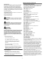 6
6
-
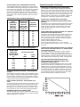 7
7
-
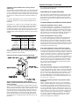 8
8
-
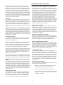 9
9
-
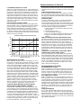 10
10
-
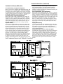 11
11
-
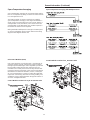 12
12
-
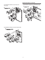 13
13
-
 14
14
-
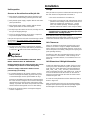 15
15
-
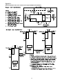 16
16
-
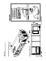 17
17
-
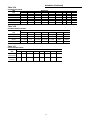 18
18
-
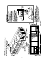 19
19
-
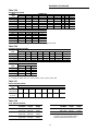 20
20
-
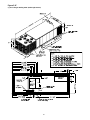 21
21
-
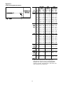 22
22
-
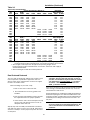 23
23
-
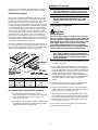 24
24
-
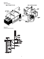 25
25
-
 26
26
-
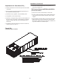 27
27
-
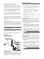 28
28
-
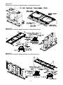 29
29
-
 30
30
-
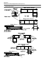 31
31
-
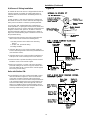 32
32
-
 33
33
-
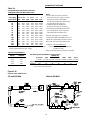 34
34
-
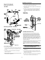 35
35
-
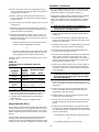 36
36
-
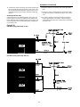 37
37
-
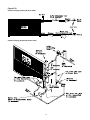 38
38
-
 39
39
-
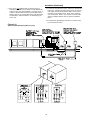 40
40
-
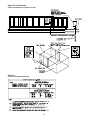 41
41
-
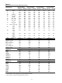 42
42
-
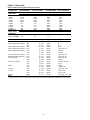 43
43
-
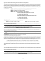 44
44
-
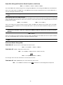 45
45
-
 46
46
-
 47
47
-
 48
48
-
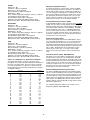 49
49
-
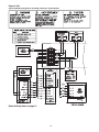 50
50
-
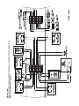 51
51
-
 52
52
-
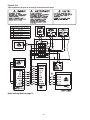 53
53
-
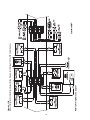 54
54
-
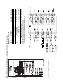 55
55
-
 56
56
-
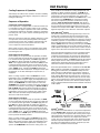 57
57
-
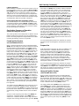 58
58
-
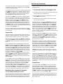 59
59
-
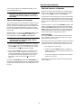 60
60
-
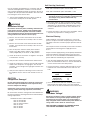 61
61
-
 62
62
-
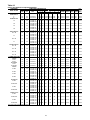 63
63
-
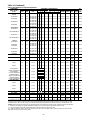 64
64
-
 65
65
-
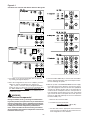 66
66
-
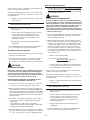 67
67
-
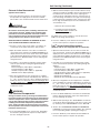 68
68
-
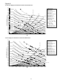 69
69
-
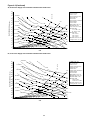 70
70
-
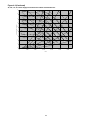 71
71
-
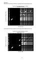 72
72
-
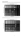 73
73
-
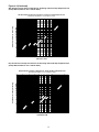 74
74
-
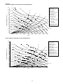 75
75
-
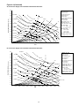 76
76
-
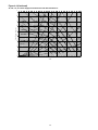 77
77
-
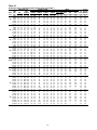 78
78
-
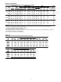 79
79
-
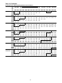 80
80
-
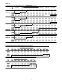 81
81
-
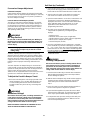 82
82
-
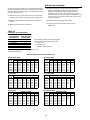 83
83
-
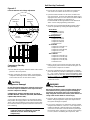 84
84
-
 85
85
-
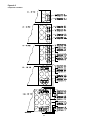 86
86
-
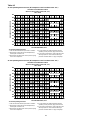 87
87
-
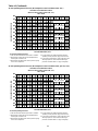 88
88
-
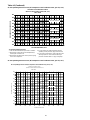 89
89
-
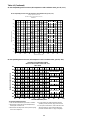 90
90
-
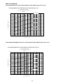 91
91
-
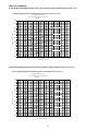 92
92
-
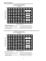 93
93
-
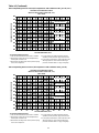 94
94
-
 95
95
-
 96
96
-
 97
97
-
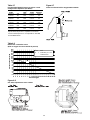 98
98
-
 99
99
-
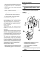 100
100
-
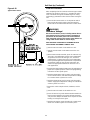 101
101
-
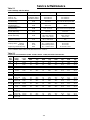 102
102
-
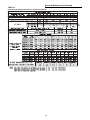 103
103
-
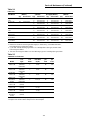 104
104
-
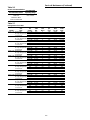 105
105
-
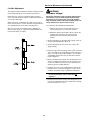 106
106
-
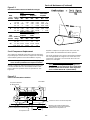 107
107
-
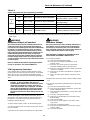 108
108
-
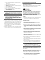 109
109
-
 110
110
-
 111
111
-
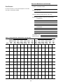 112
112
-
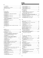 113
113
-
 114
114
-
 115
115
-
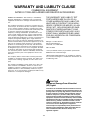 116
116
-
 117
117
-
 118
118


Trane INTELLIPAK SEHG-C90 User manual
- Category
- Heat pumps
- Type
- User manual
Ask a question and I''ll find the answer in the document
Finding information in a document is now easier with AI
Related papers
-
Trane RT-SVX10C-EN User manual
-
-
-
-
Trane Outside Air Control Installation guide
-
-
-
Trane IntelliPak SXHF C50 User manual
-
-
Other documents
-
Broan PCRDP Installation guide
-
AAON RN-040 Installation, Operation & Maintenance Manual
-
-
Infinity M30 User manual
-
Honeywell MINI-ZONE-2 MM-2 MASTERTROL User manual
-
McQuay Skyline IM777 Installation and Maintenance Manual
-
Greenheck HVAC Coils Operating instructions
-
 McDaniel Metals DHZ25FDPGCHMM Installation guide
-
AAON RZ-045 Installation, Operation & Maintenance Manual
-
Emerson SZO22 User manual
