Lennox ML193UH070P24B Unit Information
- Category
- Water heaters & boilers
- Type
- Unit Information
This manual is also suitable for

Page 1 © 2010 Lennox Industries Inc.
Litho U.S.A.
Corp. 1025−L5 ML193UH
Service Literature
ML193UH SERIES UNITS
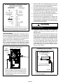
ML193UH series units are high−efficiency gas furnaces
manufactured with Lennox DuralokPlust aluminized
steel clamshell−type heat exchangers, with a stainless steel
condensing coil. ML193UH units are available in heating
input capacities of 44,000 to 132,000 Btuh (13 to 38.6 kW)
and cooling applications from 2 through 5 tons (7.0 through
17.6 kW). Refer to Engineering Handbook for proper sizing.
Units are factory equipped for use with natural gas. A kit is
available for conversion to LPG operation. All ML193UH
units are equipped with a hot surface ignition system. The
gas valve is redundant to assure safety shut−off as re-
quired by C.S.A.
The heat exchanger, burners and manifold assembly can be
removed for inspection and service. The maintenance section
gives a detailed description on how this is done.
All specifications are subject to change. Procedures outlined
in this manual are presented as a recommendation only
and do not supersede or replace local or state codes.
WARNING
Electric shock hazard. Can cause injury
or death. Before attempting to perform
any service or maintenance, turn the
electrical power to unit OFF at discon-
nect switch(es). Unit may have multiple
power supplies.
Table of Contents
Specifications 2. . . . . . . . . . . . . . . . . . . . . . . . . . . . . . . . .
Optional Accessories 3. . . . . . . . . . . . . . . . . . . . . . . . . .
Blower Performance Data 4. . . . . . . . . . . . . . . . . . . . . .
I−Unit Components 7. . . . . . . . . . . . . . . . . . . . . . . . . . . . .
II Placement and Installation 14. . . . . . . . . . . . . . . . . . . .
III−Start−Up 35. . . . . . . . . . . . . . . . . . . . . . . . . . . . . . . . . . .
IV−Heating System Service Checks 36. . . . . . . . . . . . . .
V−Typical Operating Conditions 38. . . . . . . . . . . . . . . . . .
VI−Maintenance 39. . . . . . . . . . . . . . . . . . . . . . . . . . . . . . .
VII−Sequence of Operation and Flow Charts 41. . . . . . .
VIII−Integrated Control Troubleshooting 46. . . . . . . . . . .
WARNING
Improper installation, adjustment, alteration, service
or maintenance can cause property damage, person-
al injury or loss of life. Installation and service must
be performed by a licensed professional installer (or
equivalent), service agency or the gas supplier.
WARNING
Sharp edges.
Be careful when servicing unit to avoid sharp edges
which may result in personal injury.

Page 2
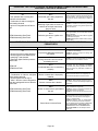
SPECIFICATIONS
Gas
Heating
Performance
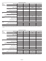
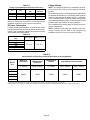
Model No. ML193UH045P36B ML193UH070P24B ML193UH070P36B ML193UH090P36C
1 AFUE 93% 93% 93% 93%
Input - Btuh 44,000 66,000 66,000 88,000
Output - Btuh 42,000 62,000 62,000 83,000
Temperature rise range - °F 25 - 55 50 - 80 40 - 70 50 - 80
Gas Manifold Pressure (in. w.g.)
Nat. Gas / LPG/Propane
3.5 / 10.0 3.5 / 10.0 3.5 / 10.0 3.5 / 10.0
High static - in. w.g. 0.50 0.50 0.50 0.50
Connections
in.
Intake / Exhaust Pipe (PVC) 2 / 2 2 / 2 2 / 2 2 / 2
Gas pipe size IPS 1/2 1/2 1/2 1/2
Condensate Drain Trap (PVC pipe) - i.d. 1/2 1/2 1/2 1/2
with eld supplied (PVC coupling) - o.d. 3/4 3/4 3/4 3/4
Indoor
Blower
Wheel nom. dia. x width - in. 10 x 8 10 x 8 10 x 8 10 x 8
Motor output - hp 1/3 1/5 1/3 1/3
Tons of add-on cooling 2.5 - 3 1.5 - 2 2.5 - 3 2 - 3
Air Volume Range - cfm 700 - 1600 390 - 1140 660 - 1615 695 - 1620
Electrical
Data
Voltage 120 volts - 60 hertz - 1 phase
Blower motor full load amps 6.1 3.1 6.1 6.1
Maximum overcurrent protection 15 15 15 15
Shipping Data lbs. - 1 package 122 125 127 143
NOTE - Filters and provisions for mounting are not furnished and must be eld provided.
1 Annual Fuel Utilization Efciency based on DOE test procedures and according to FTC labeling regulations. Isolated combustion system rating for non-weatherized
furnaces.
SPECIFICATIONS
Gas
Heating
Performance
Model No. ML193UH090P48C ML193UH110P48C ML193UH110P60C ML193UH135P60D
1 AFUE 93% 93% 93% 93%
Input - Btuh 88,000 110,000 110,000 132,000
Output - Btuh 83,000 103,000 103,000 123,000
Temperature rise range - °F 40 - 70 50 - 80 40 - 70 45 - 75
Gas Manifold Pressure (in. w.g.)
Nat. Gas / LPG/Propane
3.5 / 10.0 3.5 / 10.0 3.5 / 10.0 3.5 / 10.0
High static - in. w.g. 0.50 0.50 0.50 0.50
Connections
in.
Intake / Exhaust Pipe (PVC) 2 / 2 2 / 2 2 / 2 2 / 2
Gas pipe size IPS 1/2 1/2 1/2 1/2
Condensate Drain Trap (PVC pipe) - i.d. 1/2 1/2 1/2 1/2
with eld supplied (PVC coupling) - o.d. 3/4 3/4 3/4 3/4
Indoor
Blower
Wheel nom. dia. x width - in. 10 x 10 10 x 10 11 ½ x 10 11 ½ x 10
Motor output - hp 1/2 1/2 1 1
Tons of add-on cooling 3 - 4 3 - 4 4 - 5 4 - 5
Air Volume Range - cfm 900 - 2025 850 - 2030 1210 - 2525 1340 - 2800
Electrical
Data
Voltage 120 volts - 60 hertz - 1 phase
Blower motor full load amps 8.2 8.2 11.5 11.5
Maximum overcurrent protection 15 15 15 15
Shipping Data lbs. - 1 package 146 155 161 178
NOTE - Filters and provisions for mounting are not furnished and must be eld provided.
1 Annual Fuel Utilization Efciency based on DOE test procedures and according to FTC labeling regulations. Isolated combustion system rating for non-weatherized
furnaces.

Page 3
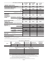
GAS HEAT ACCESSORIES
Input
High Altitude
Pressure Switch Kit
Natural Gas to
LPG/Propane Kit
LPG/Propane
to Natural Gas Kit
Natural Gas
High Altitude
Orice Kit
4501 - 7500 ft. 7501 - 10,000 ft. 0 - 7500 ft. 0 - 7500 ft. 7501- 10,000 ft.
all models 74W90 74W91 69W73 73W81 73W37
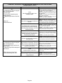
OPTIONAL ACCESSORIES - MUST BE ORDERED EXTRA
“B” Width
Models
“C” Width
Models
“D” Width
Models
CABINET ACCESSORIES
Horizontal Suspension Kit - Horizontal only 51W10 51W10 51W10
Return Air Base - Upow only 50W98 50W99 51W00
CONDENSATE DRAIN KITS
Condensate Drain Heat Cable 6 ft. 26K68 26K68 26K68
24 ft. 26K69 26K69 26K69
50 ft. 26K70 26K70 26K70
Heat Cable Tape Fiberglass - 1/2 in. x 66 ft. 36G53 36G53 36G53
Aluminum foil - 2 in. x 60 ft. 16P89 16P89 16P89
Crawl Space Vent Drain Kit 51W18 51W18 51W18
CONTROLS
Twinning Kit 65W80 65W80 65W80
FILTER KITS
1 Air Filter and
Rack Kit
Horizontal (end) Size of lter - in. 87L96 - 18 x 25 x 1 87L97 - 20 x 25 x 1 87L98 - 25 x 25 x 1
Side Return Single 44J22 44J22 44J22
Ten Pack 66K63 66K63 66K63
Size of lter - in. 16 x 25 x 1 16 x 25 x 1 16 x 25 x 1
NIGHT SERVICE KITS
Night Service Kit 51W03 51W03 51W03
TERMINATION KITS
See Installation Instructions for specic venting information.
Termination Kits -
Direct Vent
Applications Only
Concentric US - 2 in. 71M80 69M29 - - -
3 in. - - - 60L46 60L46
Canada - 2 in. 44W92 44W92 - - -
3 in. - - - 44W93 44W93
Flush-Mount 2, 2-1/2 or 3 in. 51W11 51W11 51W11
Wall - Close
Couple
US - 2 in. 22G44 - - - - - -
3 in. 44J40 44J40 44J40
Wall - Close
Couple WTK
Canada - 2 in. 30G28 - - - - - -
3 in. 81J20 81J20 81J20
Termination Kits -
Direct or Non-
Direct vent
Roof 2 in. 15F75 15F75 - - -
Wall Ring Kit 2 in. 15F74 3 15F74 - - -
Roof Termination Flashing Kit - Direct or
Non-Direct Vent (2 ashings)
2 in. 44J41 44J41 44J41
1 Cleanable polyurethane frame type lter.
2 Kits contain enough parts for two, non−direct vent installations.
3 Non−direct vent only.
NOTE - Termination Kits 44W92, 44W93, 30G28, 81J20 are certied to ULC S636 standard for use in Canada only.
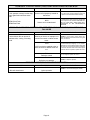
INSTALLATION CLEARANCES - INCHES (MM)
Sides 1 0 inches (0 mm)
Rear 0 inches (0 mm)
Top/Plenum 1 inch (25 mm)
Front 0 inches (0 mm)
Front (service/alcove) 24 inches (610 mm)
Floor 2 Combustible
NOTE − Air for combustion must conform to the methods outlined in the National Fuel Gas Code (NFPA 54/ANSI−Z223.1)
or the National Standard of Canada CAN/CSA−B149.1 Natural Gas and Propane Installation Code”.
NOTE − In the U.S. ue sizing must conform to the methods outlined in the current National Fuel Gas Code (NFPA 54/
ANSI−Z223.1) or applicable provisions of local building codes. In Canada ue sizing must conform to the methods
outlined in National Standard of Canada CAN/CSA−B149.1.
1 Allow proper clearances to accommodate condensate trap and vent pipe installation.
2 Do not install the furnace directly on carpeting, tile, or other combustible materials other than wood ooring.

Page 4
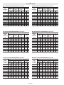
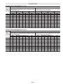
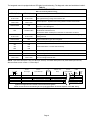
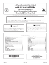
BLOWER DATA
ML193UH070P24B PERFORMANCE (Less Filter)
External
Static
Pressure
in. w.g.
Air Volume / Watts at Various Blower Speeds
High Medium-
High
Medium-
Low Low
cfm Watts cfm Watts cfm Watts cfm Watts
0.00 1140 455 920 365 765 295 710 265
0.10 1135 445 900 360 765 290 690 255
0.20 1125 430 895 350 755 285 680 255
0.30 1090 415 870 340 725 280 660 250
0.40 1065 405 870 325 715 270 635 245
0.50 1020 390 825 315 675 260 605 235
0.60 945 365 780 300 640 250 555 225
0.70 910 350 740 295 585 240 505 220
0.80 790 325 670 275 510 225 455 205
0.90 735 310 575 255 460 220 390 195
ML193UH090P36C PERFORMANCE (Less Filter)
External
Static
Pressure
in. w.g.
Air Volume / Watts at Various Blower Speeds
High Medium-
High
Medium-
Low Low
cfm Watts cfm Watts cfm Watts cfm Watts
0.00 1620 745 1340 620 1130 500 965 405
0.10 1610 720 1335 595 1135 490 975 395
0.20 1565 695 1335 565 1145 465 970 385
0.30 1525 665 1300 555 1135 455 970 370
0.40 1485 635 1295 520 1110 435 960 355
0.50 1431 600 1260 495 1090 405 940 345
0.60 1365 570 1210 475 1035 390 900 330
0.70 1295 535 1155 445 995 365 860 305
0.80 1200 505 1065 415 930 340 745 270
0.90 1060 460 955 375 820 305 695 260
ML193UH090P48C PERFORMANCE (Less Filter)
External
Static
Pressure
in. w.g.
Air Volume / Watts at Various Blower Speeds
High Medium-
High
Medium-
Low Low
cfm Watts cfm Watts cfm Watts cfm Watts
0.00 2025 900 1690 780 1395 645 1200 540
0.10 1995 880 1705 760 1390 635 1205 525
0.20 1925 835 1675 715 1405 605 1205 505
0.30 1850 795 1640 680 1400 580 1170 490
0.40 1790 760 1575 645 1395 560 1170 475
0.50 1700 725 1540 625 1350 535 1140 450
0.60 1610 690 1455 580 1295 505 1100 430
0.70 1540 645 1365 550 1225 480 1030 405
0.80 1415 615 1265 510 1125 445 980 385
0.90 1270 565 1165 470 1060 420 900 350
ML193UH110P48C PERFORMANCE (Less Filter)
External
Static
Pressure
in. w.g.
Air Volume / Watts at Various Blower Speeds
High Medium-
High
Medium-
Low Low
cfm Watts cfm Watts cfm Watts cfm Watts
0.00 2030 905 1750 805 1425 665 1225 530
0.10 1950 865 1755 770 1430 630 1215 515
0.20 1935 840 1675 735 1455 610 1230 505
0.30 1885 810 1660 685 1410 585 1200 485
0.40 1830 780 1585 645 1385 570 1190 470
0.50 1750 740 1565 630 1320 535 1165 455
0.60 1660 695 1485 585 1280 505 1105 425
0.70 1540 665 1380 555 1230 485 1060 405
0.80 1420 615 1290 520 1140 445 945 375
0.90 1290 575 1175 470 1045 410 850 350
ML193UH045P36B PERFORMANCE (Less Filter)
External
Static
Pressure
in. w.g.
Air Volume / Watts at Various Blower Speeds
High Medium-
High
Medium-
Low Low
cfm Watts cfm Watts cfm Watts cfm Watts
0.00 1600 700 1370 590 1160 475 1005 400
0.10 1600 685 1355 565 1155 465 1015 390
0.20 1550 650 1330 540 1150 445 1000 380
0.30 1480 625 1295 515 1140 430 975 365
0.40 1425 590 1280 490 1105 415 975 350
0.50 1355 565 1190 460 1085 395 940 335
0.60 1320 545 1165 435 1030 375 900 315
0.70 1225 500 1110 425 975 355 855 310
0.80 1135 480 1050 395 920 330 780 280
0.90 1025 445 950 360 800 295 700 255
ML193UH070P36B PERFORMANCE (Less Filter)
External
Static
Pressure
in. w.g.
Air Volume / Watts at Various Blower Speeds
High Medium-
High
Medium-
Low Low
cfm Watts cfm Watts cfm Watts cfm Watts
0.00 1615 680 1355 570 1140 480 1030 400
0.10 1565 660 1365 545 1150 465 1020 385
0.20 1535 630 1340 525 1150 440 1025 375
0.30 1440 600 1300 500 1110 420 1000 350
0.40 1405 570 1255 470 1075 400 975 345
0.50 1340 535 1200 445 1045 380 945 330
0.60 1255 500 1125 420 995 355 875 310
0.70 1165 475 1080 395 935 335 820 290
0.80 1060 455 990 365 870 315 750 265
0.90 955 425 895 345 750 285 660 245

Page 5
BLOWER DATA
ML193UH110P60C PERFORMANCE (Less Filter)
External
Static
Pressure
in. w.g.
Air Volume / Watts at Different Blower Speeds
Bottom Return Air, Side Return Air with Optional Return
Air Base, Return Air from Both Sides or Return Air from
Bottom and One Side.
Single Side Return Air − Air volumes in bold require eld
fabricated transition to accommodate 20 x 25 x 1 in. air lter
in order to maintain proper air velocity.
High Medium-High Medium-Low Low High Medium-High Medium-Low Low
cfm Watts cfm Watts cfm Watts cfm Watts cfm Watts cfm Watts cfm Watts cfm Watts
0.00 2525 1560 2175 1165 1820 905 1465 725 2520 1545 2135 1150 1750 905 1445 720
0.10 2585 1545 2200 1135 1860 900 1475 710 2555 1545 2135 1115 1775 890 1470 715
0.20 2515 1505 2150 1110 1840 890 1490 705 2465 1480 2105 1085 1775 875 1465 705
0.30 2445 1445 2135 1065 1790 870 1500 690 2370 1430 2045 1055 1750 855 1460 690
0.40 2340 1385 2065 1035 1770 845 1500 675 2275 1375 1990 1010 1730 830 1460 680
0.50 2230 1350 1985 985 1755 810 1470 665 2185 1345 1930 970 1690 800 1460 655
0.60 2130 1295 1920 950 1685 785 1425 640 2060 1290 1850 935 1650 780 1420 635
0.70 2030 1250 1815 905 1640 760 1405 625 1930 1230 1760 900 1580 750 1355 610
0.80 1920 1190 1735 865 1560 725 1350 605 1825 1180 1660 855 1505 710 1290 585
0.90 1735 1135 1620 830 1450 685 1270 575 1665 1130 1520 810 1415 675 1210 560
ML193UH135P60D PERFORMANCE (Less Filter)
External
Static
Pressure
in. w.g.
Air Volume / Watts at Different Blower Speeds
Bottom Return Air, Side Return Air with Optional Return
Air Base, Return Air from Both Sides or Return Air from
Bottom and One Side.
Single Side Return Air − Air volumes in bold require eld
fabricated transition to accommodate 20 x 25 x 1 in. air lter
in order to maintain proper air velocity.
High Medium-High Medium-Low Low High Medium-High Medium-Low Low
cfm Watts cfm Watts cfm Watts cfm Watts cfm Watts cfm Watts cfm Watts cfm Watts
0.00 2800 1715 2155 1160 1730 900 1375 695 2720 1685 2110 1135 1670 905 1355 705
0.10 2770 1665 2170 1145 1740 895 1415 700 2660 1650 2110 1115 1725 895 1390 700
0.20 2690 1635 2150 1110 1770 890 1450 700 2600 1585 2125 1090 1750 885 1450 695
0.30 2590 1560 2140 1080 1785 870 1455 695 2535 1525 2075 1065 1750 865 1465 685
0.40 2500 1535 2105 1055 1785 855 1475 690 2400 1490 2055 1030 1715 845 1460 680
0.50 2420 1465 2050 1025 1770 835 1465 665 2335 1420 2000 1005 1725 825 1455 660
0.60 2330 1410 2015 995 1720 810 1460 655 2270 1385 1950 970 1720 800 1445 650
0.70 2225 1370 1965 960 1690 785 1450 650 2175 1335 1895 950 1665 780 1430 635
0.80 2150 1335 1875 925 1655 755 1435 630 2075 1295 1840 910 1605 745 1400 620
0.90 2025 1290 1830 890 1575 720 1375 605 1975 1255 1755 875 1540 725 1340 590

Page 6
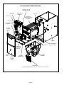
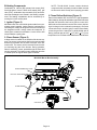
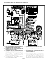
ML193UH PARTS IDENTIFICATION
FIGURE 1
TOP CAP
CABINET
BURNER BOX
ASSEMBLY
SIGHT
GLASS
DuralokPlusTM
HEAT EXCHANGER
ASSEMBLY
CONTROL BOX
(includes integrated itegrated control, transformer and interlock switch)
COMBUSTION AIR
INDUCER
BLOWER
ACCESS
DOOR
BURNER
ACCESS
PANEL
COMBUSTION
AIR PRESSURE
SWITCH
PRIMARY LIMIT
GAS VALVE
BLOWER
ASSEMBLY
FLEXIBLE NO−HUB
EXHAUST COLLAR
FLUE COLLAR
MANIFOLD
COLD END
HEADER BOX
BAG ASSEMBLIES
(shipping location)

Page 7
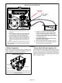
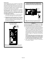
I−UNIT COMPONENTS
ML193UH unit components are shown in figure 1. The
combustion air inducer, gas valve and burners can be ac-
cessed by removing the burner access panel. The blower
and control box can be accessed by removing the blow-
er access door.
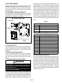
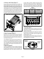
A−Control Box Components (Figure 2)
Unit transformer (T1) and integrated ignition control (A92)
are located in the control box. In addition, a door interlock
switch (S51) is located in the control box.
FIGURE 2
DOOR INTERLOCK
SWITCH (S51)
INTEGRATED IGNITION
CONTROL
(A92)
TRANSFORMER
(T1)
ML193UH Control Box
1. Transformer (T1)
A transformer located in the control box provides power to
the low voltage section of the unit. The transformers on all
models are rated at 40VA with a 120V primary and 24V
secondary.
2. Door Interlock Switch (S51)
A door interlock switch rated 14A at 120VAC is located on
the control box. The switch is wired in series with line volt-
age. When the blower door is removed the unit will shut
down.
3. Integrated Ignition Control (A92)
WARNING
Shock hazard.
Disconnect power before servicing. Control is not
field repairable. If control is inoperable, simply re-
place entire control.
Can cause injury or death. Unsafe operation will
result if repair is attempted.
The ignition control system consists of an integrated con-
trol (figure 4) ignitor (figure 6) and flame sensor (figure 6).
The integrated control and ignitor work in combination to
ensure furnace ignition and ignitor durability. The inte-
grated control, controls all major furnace operations. The
integrated control also features two LED lights (DS1 red
and DS2 green) for troubleshooting and two accessory
terminals rated at (1) one amp. The integrated control also
features a (3) amp fuse for overcurrent protection. Tables 1
and 2 show jack plug terminal designations. See table 3 for
troubleshooting diagnostic codes. The mini−nitride ignitor
is made from a non−porous, high strength proprietary ce-
ramic material that provides long life and trouble free
maintenance. The integrated control continuously moni-
tors line voltage and maintains the ignitor power at a con-
sistent level to provide proper lighting and maximum igni-
tor life.
TABLE 1
4−Pin Terminal Designation
PIN # FUNCTION
1Combustion Air Inducer Line
2Ignitor Line
3Combustion Air Inducer Neutral
4Ignitor Neutral
TABLE 2
12−Pin Terminal Designations
PIN # FUNCTION
1High Limit Output
2Not Used
324V Line
4Not Used
5Rollout Switch Out
624V Neutral
7High Limit Input
8 Ground
9Gas Valve Common
10 Pressure Switch In
11 Rollout Switch In
12 Gas Valve Out
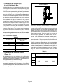
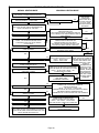
Electronic Ignition (See Figure 5)
On a call for heat the integrated control monitors the com-
bustion air inducer prove switch. The integrated control will
not begin the heating cycle if the prove switch is closed (by−
passed). Once the prove switch is determined to be open,
the combustion air inducer is energized. When the differen-
tial in the prove switch is great enough, the prove switch
closes and a 15−second pre−purge begins. If the prove
switch is not proven within 2−1/2 minutes, the integrated
control goes into Watchguard−Pressure Switch mode for a
5−minute re−set period.

Page 8
After the 15−second pre−purge period, the ignitor warms up
for 20 seconds during which the gas valve opens at 19 sec-
onds for a 4−second trial for ignition. The ignitor remains
energized for the first 3 seconds during the 4 second trial. If
ignition is not proved during the 4−second period, the inte-
grated control will try four more times with an inter purge
and warm−up time between trials of 35 seconds. After a to-
tal of five trials for ignition (including the initial trial), the inte-
grated control goes into Watchguard−Flame Failure mode.
After a 60−minute reset period, the integrated control will
begin the ignition sequence again.
The integrated control has an added feature of ignitor pow-
er regulation to maintain consistent lighting and longer igni-
tor life under all line voltage conditions.
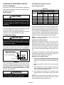
Fan Control
The fan on time of 30 seconds is not adjustable. The fan off
delay (amount of time that the blower operates after the
heat demand has been satisfied) may be adjusted by
changing the jumper position across the five pins on the
integrated control. The unit is shipped with a factory fan off
setting of 90 seconds. The fan off delay affects comfort and
is adjustable to satisfy individual applications. Adjust the
fan off delay to achieve a supply air temperature between
90° and 110°F at the moment that the blower is de−ener-
gized. Longer off delay settings provide lower return air
temperatures; shorter settings provide higher return air
temperatures. See figure 3.
FIGURE 3
FAN-OFF TIME IN SECONDS
To adjust fan−off timing, reposition jumper across pins
to achieve desired setting.
NO JUMPER
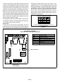
FIGURE 4
INTEGRATED CONTROL
(Automatic Hot Surface Ignition System)
TERMINAL DESIGNATIONS
HUM
LINE
XFMR
EAC
COOL
HEAT
PARK
FLAME
NEUTRALS
Humidifier (120VAC)
Input (120VAC)
Transformer (120VAC)
Electronic Air Cleaner (120VAC)
Blower − Cooling Speed (120VAC)
Blower − Heating Speed (120VAC)
Dead terminals to park alternate spd taps
Flame sensor
Neutral terminals (120VAC)
3 AMP, 32 VAC FUSE
BLOWER OFF
DELAY JUMPER
LED 1 LED 2

Page 9
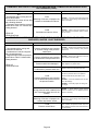
The integrated control is equipped with two LED lights for troubleshooting. The diagnostic codes are listed below in table 3.
TABLE 3
DIAGNOSTIC CODES
Make sure to Identify LED’S Correctly.
LED #1 (Red) LED #2 (Green) DESCRIPTION
SIMULTANEOUS
SLOW FLASH
SIMULTANEOUS
SLOW FLASH
Power on − Normal operation.
Also signaled during cooling and continuous fan.
SIMULTANEOUS
FAST FLASH
SIMULTANEOUS
FAST FLASH Normal operation − signaled when heating demand initiated at thermostat.
SLOW FLASH ON Primary or secondary limit switch open. Limit must close within 3 minutes or unit
goes into 1 hour Watchguard.
OFF SLOW FLASH
Pressure prove switch open.
OR: Blocked inlet/exhaust vent;
OR: Pressure switch closed prior to activation of combustion air inducer.
ALTERNATING
SLOW FLASH
ALTERNATING
SLOW FLASH
Watchguard 1 hour −− burners failed to ignite or lost flame 5 times during single
heating demand.
SLOW FLASH OFF Flame sensed without gas valve energized.
ON SLOW FLASH Rollout switch open. OR: 12-pin connector improperly attached.
ON
ON
OFF
ON
OFF
ON
Circuit board failure or control wired incorrectly.
FAST FLASH SLOW FLASH Main power polarity reversed. Switch line and neutral.
SLOW FLASH FAST FLASH Low flame signal. Measures below 1.5 microamps. Replace flame sense rod.
ALTERNATING
FAST FLASH
ALTERNATING
FAST FLASH
Improper main ground.
OR: Line voltage below 90 volts.
NOTE − Slow flash rate equals 1 Hz (one flash per second). Fast flash rate equals 3 Hz (three flashes per second).
Minimum flame sense current = 0.5 microAmps.
FIGURE 5
DEMAND
CAI
GAS VALVE
ON
OFF
IGNITOR
15 Sec.
Pre −Purge
20 sec.
Ignitor Warmup
*4
Sec.Trial
for Ign. Post
Purge
5 SEC
**Blower on time will be 45 seconds after gas valve is energized. Blower off time will depend on OFF TIME" Setting.
INDOOR BLOWER
**Blower On"
Delay
End of
Heat Demand Blower
Off
Time
*Ignitor will energize the first 3 seconds of the 4 second trial for ignition

Page 10
B−Heating Components
Combustion air inducer (B6), primary limit control (S10),
SureLight ignitor, burners, flame rollout switch (S47), gas
valve (GV1), combustion air prove switch (S18), and clam-
shell heat exchangers are located in the heating compart-
ment. The heating compartment can be accessed by re-
moving the burner access panel.
1. Ignitor (Figure 6)
ML193UH units use a mini−nitride ignitor made from a pro-
prietary ceramic material. Ignitor longevity is enhanced by
controlling the voltage to the ignitor. Due to this feature of
the integrated control, voltage cannot be measured. To
check ignitor, measure its resistance. A value of 50 to 450
ohms indicates a good ignitor.
2. Flame Sensor (Figure 6)
A flame sensor is located on the left side of the burner sup-
port. The sensor is mounted on the front burner box plate
and the tip protrudes into the flame envelope of the left−
most burner. The sensor can be removed for service with-
out removing any part of the burners. During operation,
flame is sensed by current passed through the flame and
sensing electrode. The ignition control allows the gas valve
to remain open as long as flame signal is sensed.
NOTE − The ML193UH furnace contains electronic
components that are polarity sensitive. Make sure that
the furnace is wired correctly and is properly grounded.
3. Flame Rollout Switches (Figure 6)
Flame rollout switches S47 are SPST N.C. high temperature
limits located on the top left and bottom right of the front buner
box plate. S47 is wired to the burner ignition control A92.
When either of the switches sense flame rollout (indicat-
ing a blockage in the combustion passages), the flame
rollout switch trips, and the ignition control immediately
closes the gas valve. Switch S47 in all ML193UH units is
factory preset to open at 210_F + 12_F (99_C + 6.7_C) on a
temperature rise. All flame rollout switches are manual reset.
FIGURE 6
ML193UH Burner Box Assembly
IGNITOR
FLAME SENSOR
ROLLOUT SWITCHES
GAS VALVE
BURNERS
ORIFICES
FRONT BURNER BOX PLATE

Page 11
4. Primary Limit Control (Figure 7)
Primary limit (S10) used on ML193UH units is located in the
heating vestibule panel. When excess heat is sensed in the
heat exchanger, the limit will open. Once the limit opens, the
furnace control energizes the supply air blower and de−en-
ergizes the gas valve. The limit automatically resets when
unit temperature returns to normal. The switch is factory
set and cannot be adjusted. For limit replacement remove
wires from limit terminals, remove mounting screws, rotate
limit switch 90 degrees and slowly remove from the vesti-
bule panel. Install replacement limit with same care.
FIGURE 7
Primary Limit Location and Heat Exchanger
Install limit face down
5. Heat Exchanger (Figure 7)
ML193UH units use an aluminized steel primary and
stainless steel secondary heat exchanger assembly.
Heat is transferred to the air stream from all surfaces of
the heat exchanger. The shape of the heat exchanger en-
sures maximum efficiency.
The combustion air inducer pulls fresh air through the burn-
er box. This air is mixed with gas in the burners. The gas /
air mixture is then burned at the entrance of each clam-
shell. Combustion gases are then pulled through the primary
and secondary heat exchangers and exhausted out the ex-
haust vent pipe.
6. Burners (Figure 8)
All units use inshot burners. Burners are factory set and do not
require adjustment. Burners can be removed as an assembly
for service. Burner maintenance and service is detailed in the
MAINTENANCE section of this manual. Each burner uses
an orifice which is precisely matched to the burner input.
See table 4 for orifice size. The burner is supported by the
orifice and will easily slide off for service. A flame retention
ring in the end of each burner maintains correct flame length
and shape and keeps the flame from lifting off the burner head.
TABLE 4
Gas Orifice Size
Unit Fuel Orifice Size
All Natural 0.0625
All L.P./Propane 0.0340
FIGURE 8
Burner Detail Top View
FLAME SENSOR
IGNITOR
ORIFICES
7. Gas Valve (GV1)
The ML193UH uses an internally redundant valve to assure
safety shut-off. If the gas valve must be replaced, the same
type valve must be used.
24VAC terminals and gas control switch are located on
top of the valve. All terminals on the gas valve are con-
nected to wires from the ignition control. 24V applied to the
terminals opens the valve.
Inlet and outlet pressure taps are located on the valve. A
manifold adjustment screw is also located on the valve. An
LPG changeover kit is available.
FIGURE 9
Gas Valve
MANIFOLD
PRESSURE
OUTLET
PORT
INLET
PRESSURE
PORT
MANIFOLD
PRESSURE
ADJUSTMENT
SCREW

Page 12
8. Combustion Air Inducer (B6)
& Cold End Header Box
All ML193UH units use a combustion air inducer to move
air through the burners and heat exchanger during heat-
ing operation. The blower uses a shaded pole 120VAC
motor. The motor operates during all heating operation and
is controlled by integrated control A3. Blower operates con-
tinuously while there is a call for heat. The integrated con-
trol will not proceed with the ignition sequence until combus-
tion air inducer operation is sensed by the proving switches.
The combustion air inducer is installed on the cold end
header box. The cold end header box is a single piece
made of hard plastic. The box has an internal channel
where the combustion air inducer creates negative pres-
sure at unit start up. The channel contains an orifice used
to regulate flow created by the combustion air inducer.
The box has pressure taps for the combustion air inducer
pressure switch hoses. The pressure switch measures
the pressure across the combustion air inducer orifice or
difference in the channel and the box. If replacement is
necessary the gaskets used to seal the box to the
vestibule panel and the combustion air inducer to the
box, must also be replaced.
TABLE 5
ML193UH Unit Combustion Air Inducer
Orifice Size
−045 0.563
−070 0.844
−090 1.00
−110 1.22
−135 1.30
9. Combustion Air Pressure Switch
(Figure 10)
ML193UH series units are equipped with a differential
pressure switch located on the cold end header box. The
switch monitors across the combustion air inducer orifice to in-
sure proper flow through the heat exchanger.
The switch is a SPST N.O. prove switch electrically con-
nected to the integrated control. The purpose of the switch is
to prevent burner operation if the combustion air inducer is not
moving enough air for proper combustion.
FIGURE 10
Pressure Switch
On start-up, the switch monitors whether the combustion air
inducer is operating. It closes a circuit to the integrated
control when the difference in pressure across the com-
bustion air inducer orifice exceeds a non−adjustable factory
setting. If the switch does not successfully sense the re-
quired differential, the switch cannot close and the fur-
nace cannot operate. If the flue or air inlet become ob-
structed during operation, the switch senses a loss of
pressure differential and opens the circuit to the integrated
control. If the condensate line is blocked, water will back up
into the header box and reduce the pressure differential
across the switch. The prove switch opens if the differential
drops below the set point. See table 6.
Checks of pressure differential can aid in troubleshooting.
When measuring the pressure differential, readings should be
taken at the pressure switch. See figure 11. Lack of differential
usually indicates problems in the intake or exhaust piping, but
may indicate problems in the heat exchanger, condens-
ing coil, header boxes, combustion inducer or other
components.
TABLE 6
Unit
Altitude ft.
0 − 4500 4501 − 7500 7501 − 10000
Set Point w.c. Set Point w.c Set Point w.c.
−045
−0.65 −0.60 −0.055
−070
−090
−110
−135
*Set point is factory set and non−adjustable

Page 13
FIGURE 11
1 − Remove thermostat demand and allow unit to
cycle off.
2 − Install a tee in the negative (−) line (red tubing) and a
tee in the positive (+) line (black tubing) running from
the pressure switch to the cold end header box.
3 − Install a manometer with hose from the negative (−)
side of the manometer to the tee installed in the
negative (−) line and with hose from the positive (+)
side of the manometer to the tee in the positive (+)
line.
NOTE − Both sides of the cold end header box are nega-
tive. However the (+) port reads less negative pressure
than the (−) port.
4 − Operate unit and observe manometer reading.
Readings will change as heat exchanger warms.
a. Take one reading immediately after start-up.
b. Take a second reading after unit has reached
steady state (approximately 5 minutes). This will be
the pressure differential.
The pressure differential should be greater
than those listed in table 6.
5 − Remove thermostat demand and allow to cycle off.
6 − Remove manometer and tee’s. Reinstall combustion
air sensing hoses to the pressure switch.
BLACK TUBING
POSITIVE
RED TUBING
NEGATIVE
Measuring Pressure Differential
C− Blower Compartment
Blower motor (B3) and capacitor (C4), are located in the
blower compartment. The blower compartment can be ac-
cessed by removing the blower access panel.
FIGURE 12
Blower Motor Housing
To Remove Blower From Unit: Disconnect Power, Remove Control
Box, Remove Bolts and Unplug Motor Wires From Control. Then
Slide Out Front of Unit.
MOTOR
CAPACITOR
BOLTS
1. Blower Motor (B3) and Capacitor (C4)
All ML193UH units use single−phase direct−drive blower mo-
tors. All motors are 120V permanent split capacitor motors
to ensure maximum efficiency. See SPECIFICATIONS table
at the front of this manual for more detail. See motor name-
plate for capacitor ratings.

Page 14
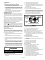
II−PLACEMENT AND INSTALLATION
Combustion, Dilution & Ventilation Air
If the ML193UH is installed as a Non−Direct Vent Fur-
nace, follow the guidelines in this section.
NOTE − In Non−Direct Vent installations, combustion air
is taken from indoors and flue gases are discharged out−
doors.
In the past, there was no problem in bringing in sufficient
outdoor air for combustion. Infiltration provided all the air
that was needed. In today’s homes, tight construction
practices make it necessary to bring in air from outside
for combustion. Take into account that exhaust fans, ap-
pliance vents, chimneys, and fireplaces force additional
air that could be used for combustion out of the house.
Unless outside air is brought into the house for combus-
tion, negative pressure (outside pressure is greater than
inside pressure) will build to the point that a downdraft
can occur in the furnace vent pipe or chimney. As a result,
combustion gases enter the living space creating a po-
tentially dangerous situation.
In the absence of local codes concerning air for combus−
tion and ventilation, use the guidelines and procedures in
this section to install ML193UH furnaces to ensure effi-
cient and safe operation. You must consider combustion
air needs and requirements for exhaust vents and gas
piping. A portion of this information has been reprinted
with permission from the National Fuel Gas Code (ANSI−
Z223.1/NFPA 54). This reprinted material is not the com-
plete and official position of the ANSI on the referenced
subject, which is represented only by the standard in its
entirety.
In Canada, refer to the CSA B149 installation codes.
CAUTION
Do not install the furnace in a corrosive or contami-
nated atmosphere. Meet all combustion and ventila-
tion air requirements, as well as all local codes.
All gas-fired appliances require air for the combustion pro-
cess. If sufficient combustion air is not available, the fur-
nace or other appliance will operate inefficiently and un-
safely. Enough air must be provided to meet the needs of all
fuel−burning appliances and appliances such as exhaust
fans which force air out of the house. When fireplaces, ex-
haust fans, or clothes dryers are used at the same time as
the furnace, much more air is required to ensure proper
combustion and to prevent a downdraft. Insufficient air
causes incomplete combustion which can result in carbon
monoxide.
In addition to providing combustion air, fresh outdoor air di-
lutes contaminants in the indoor air. These contaminants
may include bleaches, adhesives, detergents, solvents
and other contaminants which can corrode furnace compo-
nents.
The requirements for providing air for combustion and ven-
tilation depend largely on whether the furnace is installed in
an unconfined or a confined space.
Unconfined Space
An unconfined space is an area such as a basement or
large equipment room with a volume greater than 50 cubic
feet (1.42 m3) per 1,000 Btu (.29 kW) per hour of the com-
bined input rating of all appliances installed in that space.
This space also includes adjacent rooms which are not
separated by a door. Though an area may appear to be un-
confined, it might be necessary to bring in outdoor air for
combustion if the structure does not provide enough air by
infiltration. If the furnace is located in a building of tight
construction with weather stripping and caulking around
the windows and doors, follow the procedures in the Air
from Outside section.
Confined Space
A confined space is an area with a volume less than 50 cubic
feet (1.42 m3) per 1,000 Btu (.29 kW) per hour of the com−
bined input rating of all appliances installed in that space. This
definition includes furnace closets or small equipment rooms.
When the furnace is installed so that supply ducts carry air
circulated by the furnace to areas outside the space con-
taining the furnace, the return air must be handled by ducts
which are sealed to the furnace casing and which terminate
outside the space containing the furnace. This is especially
important when the furnace is mounted on a platform in a
confined space such as a closet or small equipment room.
Even a small leak around the base of the unit at the platform
or at the return air duct connection can cause a potentially
dangerous negative pressure condition. Air for combustion
and ventilation can be brought into the confined space ei-
ther from inside the building or from outside.
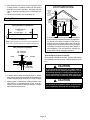
Air from Inside
If the confined space that houses the furnace adjoins a
space categorized as unconfined, air can be brought in by
providing two permanent openings between the two
spaces. Each opening must have a minimum free area of 1
square inch (645 mm2) per 1,000 Btu (.29 kW) per hour of
total input rating of all gas−fired equipment in the confined
space. Each opening must be at least 100 square inches
(64516 mm2). One opening shall be within 12 inches (305
mm) of the top of the enclosure and one opening within 12
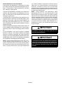
inches (305 mm) of the bottom. See figure 13.

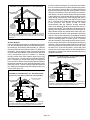
Page 15
FIGURE 13
EQUIPMENT IN CONFINED SPACE − ALL AIR FROM INSIDE
OPENINGS
(To Adjacent
Unconfined
Space)
NOTE − Each opening shall have a free area of at least one square inch
per 1,000 Btu (645mm2 per .29kW) per hour of the total input rating of
all equipment in the enclosure, but not less than 100 square inches
(64516mm.2).
ROOF TERMINATED
EXHAUST PIPE
SIDE WALL
TERMINATED
EXHAUST PIPE
(ALTERNATE
LOCATION)
ML193UH
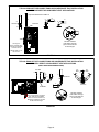
Air from Outside
If air from outside is brought in for combustion and ventila-
tion, the confined space shall be provided with two perma-
nent openings. One opening shall be within 12" (305mm)
of the top of the enclosure and one within 12" (305mm) of
the bottom. These openings must communicate directly
or by ducts with the outdoors or spaces (crawl or attic) that
freely communicate with the outdoors or indirectly
through vertical ducts. Each opening shall have a mini-
mum free area of 1 square inch per 4,000 Btu (645mm2
per 1.17kW) per hour of total input rating of all equipment
in the enclosure. When communicating with the outdoors
through horizontal ducts, each opening shall have a mini-
mum free area of 1 square inch per 2,000 Btu (645mm2
per .59kW) per total input rating of all equipment in the en-
closure (See figure 14).
FIGURE 14
EQUIPMENT IN CONFINED SPACE − ALL AIR FROM OUTSIDE
(Inlet Air from Crawl Space and Outlet Air to Ventilated Attic)
NOTE−The inlet and outlet air openings shall each have a free area
of at least one square inch per 4,000 Btu (645mm2 per 1.17kW) per
hour of the total input rating of all equipment in the enclosure.
OUTLET
AIR
INLET
AIR
VENTILATION
LOUVERS
(For unheated
crawl space)
FURNACE
ROOF TERMINATED
EXHAUST PIPE
VENTILATION LOUVERS
(Each end of attic)
SIDE WALL
TERMINATED
EXHAUST PIPE
(ALTERNATE
LOCATION)
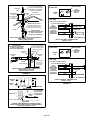
If air from outside is brought in for combustion and ventila-
tion, the confined space must have two permanent open-
ings. One opening shall be within 12 inches (305 mm) of
the top of the enclosure and one opening within 12 inches
(305 mm) of the bottom. These openings must communi-
cate directly or by ducts with the outdoors or spaces (crawl
or attic) that freely communicate with the outdoors or indi-
rectly through vertical ducts. Each opening shall have a
minimum free area of 1 square inch (645 mm2) per 4,000
Btu (1.17 kW) per hour of total input rating of all equipment
in the enclosure. See figures 14 and 15. When
communicating with the outdoors through horizontal
ducts, each opening shall have a minimum free area of 1
square inch (645 mm2) per 2,000 Btu (.56 kW) per total in-
put rating of all equipment in the enclosure. See figure 16.
When ducts are used, they shall be of the same cross−sec-
tional area as the free area of the openings to which they
connect. The minimum dimension of rectangular air ducts
shall be no less than 3 inches (75 mm). In calculating free
area, the blocking effect of louvers, grilles, or screens
must be considered. If the design and free area of protec-
tive covering is not known for calculating the size opening
required, it may be assumed that wood louvers will have
20 to 25 percent free area and metal louvers and grilles
will have 60 to 75 percent free area. Louvers and grilles
must be fixed in the open position or interlocked with the
equipment so that they are opened automatically during
equipment operation.
FIGURE 15
EQUIPMENT IN CONFINED SPACE − ALL AIR FROM OUTSIDE
(All Air Through Ventilated Attic)
NOTE−The inlet and outlet air openings shall each have a free area of
at least one square inch per 4,000 Btu (645mm2 per 1.17kW) per hour
of the total input rating of all equipment in the enclosure.
OUTLET
AIR
VENTILATION LOUVERS
(Each end of attic)
INLET AIR
(Ends 12" above
bottom)
ROOF TERMINATED
EXHAUST PIPE
SIDE WALL
TERMINATED
EXHAUST PIPE
(ALTERNATE
LOCATION)
FURNACE

Page 16
FIGURE 16
EQUIPMENT IN CONFINED SPACE −
ALL AIR FROM OUTSIDE
OUTLET AIR
INLET AIR
NOTE−Each air duct opening shall have a free area of at least one
square inch per 2,000 Btu (645mm2
per .59kW) per hour of the total
input rating of all equipment in the enclosure. If the equipment room
is located against an outside wall and the air openings communi-
cate directly with the outdoors, each opening shall have a free area
of at least 1 square inch per 4,000 Btu (645mm2 per 1.17kW) per
hour of the total input rating of all other equipment in the enclosure.
ROOF TERMINATED
EXHAUST PIPE
SIDE WALL
TERMINATED
EXHAUST PIPE
(ALTERNATE
LOCATION)
FURNACE
Pipe & Fittings Specifications
All pipe, fittings, primer and solvent cement must conform
with American National Standard Institute and the Ameri-
can Society for Testing and Materials (ANSI/ASTM) stan-
dards. The solvent shall be free flowing and contain no
lumps, undissolved particles or any foreign matter that ad-
versely affects the joint strength or chemical resistance of
the cement. The cement shall show no gelation, stratifica-
tion, or separation that cannot be removed by stirring. Re-
fer to the table 7 below for approved piping and fitting ma-
terials.
IMPORTANT
ML193UH exhaust and intake connections are made
of PVC. Use PVC primer and solvent cement when
using PVC vent pipe. When using ABS vent pipe, use
transitional solvent cement to make connections to
the PVC fittings in the unit.
CAUTION
Solvent cements for plastic pipe are flammable liq-
uids and should be kept away from all sources of
ignition. Do not use excessive amounts of solvent
cement when making joints. Good ventilation should
be maintained to reduce fire hazard and to minimize
breathing of solvent vapors. Avoid contact of cement
with skin and eyes.
Use PVC primer and solvent cement or ABS solvent cement
meeting ASTM specifications, refer to Table 7. As an alter-
nate, use all purpose cement, to bond ABS, PVC, or CPVC
pipe when using fittings and pipe made of the same materi-
als. Use transition solvent cement when bonding ABS to ei-
ther PVC or CPVC.
TABLE 7
PIPING AND FITTINGS SPECIFICATIONS
Schedule 40 PVC (Pipe) D1785
Schedule 40 PVC (Cellular Core Pipe) F891
Schedule 40 PVC (Fittings) D2466
Schedule 40 CPVC (Pipe) F441
Schedule 40 CPVC (Fittings) F438
SDR−21 PVC or SDR−26 PVC (Pipe) D2241
SDR−21 CPVC or SDR−26 CPVC (Pipe) F442
Schedule 40 ABS Cellular Core DWV (Pipe) F628
Schedule 40 ABS (Pipe) D1527
Schedule 40 ABS (Fittings) D2468
ABS−DWV (Drain Waste & Vent)
(Pipe & Fittings) D2661
PVC−DWV (Drain Waste & Vent)
Pipe & Fittings) D2665
PRIMER & SOLVENT CEMENT ASTM
SPECIFICATION
PVC & CPVC Primer F656
PVC Solvent Cement D2564
CPVC Solvent Cement F493
ABS Solvent Cement D2235
PVC/CPVC/ABS All Purpose Cement For
Fittings & Pipe of the same material D2564, D2235, F493
ABS to PVC or CPVC Transition Solvent
Cement D3138
CANADA PIPE & FITTING & SOLVENT
CEMENT MARKING
PVC & CPVC Pipe and Fittings
ULCS636
PVC & CPVC Solvent Cement
ABS to PVC or CPVC Transition Cement
Low temperature solvent cement is recommended during
cooler weather. Metal or plastic strapping may be used for
vent pipe hangers. Uniformly apply a liberal coat of PVC
primer for PVC or use a clean dry cloth for ABS to clean in-
side socket surface of fitting and male end of pipe to depth
of fitting socket.
Canadian Applications Only − Pipe, fittings, primer
and solvent cement used to vent (exhaust) this ap-
pliance must be certified to ULC S636 and supplied by a
single manufacturer as part of an approved vent (ex-
haust) system. When bonding the vent system to the fur-
nace, use ULC S636 approved One−Step Transition Ce-
ment to bond the pipe to the flue collar, or to bond the 90°
elbow or reducing 90° elbow to the flue collar. In addi-
tion, the first three feet of vent pipe from the furnace flue
collar must be accessible for inspection.

Page 17
TABLE 8
OUTDOOR TERMINATION KITS USAGE
ML193
UNIT
VENT
PIPE
DIA.
(in.)
STANDARD CONCENTRIC
Outdoor Ex-
haust Accel-
erator
(Dia. X
Length)
Outdoor Ex-
haust Accel-
erator
(Dia. X
Length)
2" Wall Plate
Kit
3" Wall Plate
Kit
2" Wall
Ring Kit
Flush-
Mount
Kit
1−1/2"
Concentric
Kit
2" Con-
centric Kit
3" Con-
centric Kit
1−1/2" X 12" 2" X 12" 22G44
or 30G28
44J40
or 81J2015F74 51W11**
71M80
or
44W92
69M29
or
44W92
60L46
or 44W93
045
2 YES YES YES* YES YES YES
2−1/2 YES YES YES* YES YES YES
3 YES YES YES* YES YES YES
070
2 YES YES YES* YES YES YES
2−1/2 YES YES YES* YES YES YES
3 YES YES YES* YES YES YES
090
2 YES YES YES YES YES YES
2−1/2 YES YES YES YES YES YES
3 YES YES YES YES YES YES
110
2 YES YES YES YES YES YES
2−1/2 YES YES YES YES YES YES
3 YES YES YES YES YES YES
135 3 YES YES YES
*Requires field−provided and installed 1−1/2" exhaust accelerator.
** Kit 51W11 is provided with a 1−1/2" accelerator which must be used for all ML193UH−045, −070 and −090 installations.
Termination kits 44W92, 44W93, 30G28 and 81J20 approved for use in Canadian installations to meet CSAB149.
The 44W92 Concentric kit is provided with a 1−1/2" accelerator which must be installed on the exhaust outlet when this kit is used with the ML193UH045P36B,
ML193UH070P24B and ML193UH070P36B furnaces.
Joint Cementing Procedure
All cementing of joints should be done according to the
specifications outlined in ASTM D 2855.
DANGER
DANGER OF EXPLOSION!
Fumes from PVC glue may ignite during system
check. Allow fumes to dissipate for at least 5 minutes
before placing unit into operation.
1 − Measure and cut vent pipe to desired length.
2 − Debur and chamfer end of pipe, removing any ridges
or rough edges. If end is not chamfered, edge of pipe
may remove cement from fitting socket and result in a
leaking joint.
3 − Clean and dry surfaces to be joined.
4 − Test fit joint and mark depth of fitting on outside of pipe.
5 − Uniformly apply a liberal coat of PVC primer for PVC or
use a clean dry cloth for ABS to clean inside socket
surface of fitting and male end of pipe to depth of fitting
socket.
NOTE − Time is critical at this stage. Do not allow prim-
er to dry before applying cement.
6 − Promptly apply solvent cement to end of pipe and in-
side socket surface of fitting. Cement should be ap-
plied lightly but uniformly to inside of socket. Take
care to keep excess cement out of socket. Apply sec-
ond coat to end of pipe.
7 − Immediately after applying last coat of cement to pipe,
and while both inside socket surface and end of pipe
are wet with cement, forcefully insert end of pipe into
socket until it bottoms out. Turn PVC pipe 1/4 turn dur-
ing assembly (but not after pipe is fully inserted) to dis-
tribute cement evenly. DO NOT turn ABS or cellular
core pipe.
NOTE − Assembly should be completed within 20 sec-
onds after last application of cement. Hammer blows
should not be used when inserting pipe.

Page 18
8 − After assembly, wipe excess cement from pipe at end
of fitting socket. A properly made joint will show a
bead around its entire perimeter. Any gaps may indi-
cate an improper assembly due to insufficient sol-
vent.
9 − Handle joints carefully until completely set.
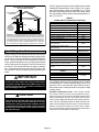
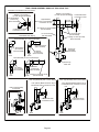
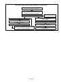
Venting Practices
FIGURE 17
* See table 7 for allowable pipe.
Piping Suspension Guidelines
NOTE − Isolate piping at the point where it exits the outside wall or
roof in order to prevent transmission of vibration to the structure.
SCHEDULE 40
PVC − 5’
all other pipe* − 3’
Wall
inside outside
24" maximum
3/4" minimum
Wall Thickness Guidelines
insulation
(if required)
1 In areas where piping penetrates joists or interior
walls, hole must be large enough to allow clearance on
all sides of pipe through center of hole using a hanger.
2. When furnace is installed in a residence where unit is
shut down for an extended period of time, such as a
vacation home, make provisions for draining conden-
sate collection trap and lines.
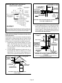
CHIMNEY
OR GAS
VENT
(Check sizing
for water
heater only)
FURNACE
(Replaced
by ML193)
WATER
HEATER
OPENINGS
(To Adjacent
Room)
If an ML193UH furnace replaces a furnace which
was commonly vented with another gas appliance,
the size of the existing vent pipe for that gas ap-
pliance must be checked. Without the heat of the
original furnace flue products, the existing vent pipe
is probably oversized for the single water heater or
other appliance. The vent should be checked for
proper draw with the remaining appliance.
FIGURE 18
REPLACING FURNACE THAT WAS
PART OF A COMMON VENT SYSTEM
Exhaust Piping (Figures 21 and 22)
Route piping to outside of structure. Continue with installa-
tion following instructions given in piping termination sec-
tion.
CAUTION
Do not discharge exhaust into an existing stack or
stack that also serves another gas appliance. If verti-
cal discharge through an existing unused stack is re-
quired, insert PVC pipe inside the stack until the end
is even with the top or outlet end of the metal stack.
CAUTION
The exhaust vent pipe operates under positive pres-
sure and must be completely sealed to prevent leak-
age of combustion products into the living space.

Page 19
Vent Piping Guidelines
The ML193UH can be installed as either a Non−Direct
Vent or a Direct Vent gas central furnace.
NOTE − In Non-Direct Vent installations, combustion air is
taken from indoors and flue gases are discharged outdoors.
In Direct Vent installations, combustion air is taken from out-
doors and flue gases are discharged outdoors.
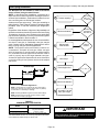
Intake and exhaust pipe sizing −− Size pipe according to
tables 9 and 10. Table 9 lists the minimum vent pipe lengths
permitted. Table 10 lists the maximum pipe lengths per-
mitted.
Regardless of the diameter of pipe used, the standard roof
and wall terminations described in section Exhaust Piping
Terminations should be used. Exhaust vent termination
pipe is sized to optimize the velocity of the exhaust gas as
it exits the termination. Refer to table 11.
In some applications which permit the use of several differ-
ent sizes of vent pipe, a combination vent pipe may be
used. Contact Lennox’ Application Department for assis-
tance in sizing vent pipe in these applications.
NOTE − The exhaust collar on all models is sized to ac-
commodate 2" Schedule 40 vent pipe. When vent pipe
which is larger than 2" must be used in an upflow applica-
tion, a transition must be applied at the exhaust collar in
order to properly step to the larger diameter vent pipe.
Contact the Application Department for more information
concerning sizing of vent systems which include multiple
pipe sizes.
FIGURE 19
12" max
of straight pipe
Exhaust Pipe
12" Min.
NOTE − Exhaust pipe MUST be glued to furnace exhaust fittings.
NOTE − All horizontal runs of exhaust pipe must slope back to-
ward unit. A minimum of 1/4" (6mm) drop for each 12" (305mm)
of horizontal run is mandatory for drainage.
NOTE − Exhaust piping should be checked carefully to make
sure there are no sags or low spots.
Horizontal Application
TABLE 9
MINIMUM VENT PIPE LENGTHS
ML193UH
MODEL
MIN. VENT LENGTH*
045, 070, 090, 110 15 ft. or
5 ft plus 2 elbows or
10 ft plus 1 elbow
135**
*Any approved termination may be added to the minimum length listed.
**ML193UH135P60D must have 3" to 2" reducing ell (supplied or field replace-
ment Canadian kit) installed directly into unit flue collar.
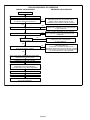
Use the following steps to correctly size vent pipe diameter.
1
2
3
4
5
6
045, 070,
090, 110
or 135 btuh
Which termination?
Standard or
Concentric?
See table 8
Intake or
exhaust
Which needs
most elbows?
How many?
2", 2 1/2", 3"
Desired pipe size?
Use table 5 to find
max. pipe length.
FIGURE 20
What is the altitude?
7
Furnace capacity?
IMPORTANT
Do not use screens or perforated metal in exhaust or
intake terminations. Doing so will cause freeze−ups
and may block the terminations.

Page 20
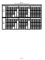
TABLE 10
Maximum Allowable Vent Length in Feet
Standard Termination at Elevation 0 − 10,000 ft.
Number
Of 90°
Ebows
Used
Pipe
Size 2" 2−1/2" 3"
Model 045 070 090 110 135 045 070 090 110 135 045 070 090 110 135
1 81 66 44 24
n/a
115 100 68 43
n/a
137 137 118 118 114
2 76 61 39 19 110 95 63 38 132 132 113 113 109
3 71 56 34 14 105 90 58 33 127 127 108 108 104
4 66 51 29
n/a
100 85 53 28 122 122 103 103 99
5 61 46 24 95 80 48 23 117 117 98 98 94
6 56 41 19 90 75 43 18 112 112 93 93 89
7 51 36 14 85 70 38 13 107 107 88 88 84
8 46 31
n/a
80 65 33
n/a
102 102 83 83 79
9 41 26 75 60 28 97 97 78 78 74
10 36 21 70 55 23 92 92 73 73 69
Concentric Termination Elevation 0 − 10,000 ft.
Number
Of 90°
Ebows
Used
Pipe
Size 2" 2−1/2" 3"
Model 045 070 090 110 135 045 070 090 110 135 045 070 090 110 135
1 73 58 42 22
n/a
105 90 64 39
n/a
121 121 114 114 105
2 68 53 37 17 100 85 59 34 116 116 109 109 100
3 63 48 32 12 95 80 54 29 111 111 104 104 95
4 58 43 27
n/a
90 75 49 24 106 106 99 99 90
5 53 38 22 85 70 44 19 101 101 94 94 85
6 48 33 17 80 65 39 14 96 96 89 89 80
7 43 28 12 75 60 34
n/a
91 91 84 84 75
8 38 23
n/a
70 55 29 86 86 79 79 70
9 33 18 65 50 24 81 81 74 74 65
10 28 13 60 45 19 76 76 69 69 60
Page is loading ...
Page is loading ...
Page is loading ...
Page is loading ...
Page is loading ...
Page is loading ...
Page is loading ...
Page is loading ...
Page is loading ...
Page is loading ...
Page is loading ...
Page is loading ...
Page is loading ...
Page is loading ...
Page is loading ...
Page is loading ...
Page is loading ...
Page is loading ...
Page is loading ...
Page is loading ...
Page is loading ...
Page is loading ...
Page is loading ...
Page is loading ...
Page is loading ...
Page is loading ...
Page is loading ...
Page is loading ...
Page is loading ...
Page is loading ...
Page is loading ...
-
 1
1
-
 2
2
-
 3
3
-
 4
4
-
 5
5
-
 6
6
-
 7
7
-
 8
8
-
 9
9
-
 10
10
-
 11
11
-
 12
12
-
 13
13
-
 14
14
-
 15
15
-
 16
16
-
 17
17
-
 18
18
-
 19
19
-
 20
20
-
 21
21
-
 22
22
-
 23
23
-
 24
24
-
 25
25
-
 26
26
-
 27
27
-
 28
28
-
 29
29
-
 30
30
-
 31
31
-
 32
32
-
 33
33
-
 34
34
-
 35
35
-
 36
36
-
 37
37
-
 38
38
-
 39
39
-
 40
40
-
 41
41
-
 42
42
-
 43
43
-
 44
44
-
 45
45
-
 46
46
-
 47
47
-
 48
48
-
 49
49
-
 50
50
-
 51
51


Lennox ML193UH070P24B Unit Information
- Category
- Water heaters & boilers
- Type
- Unit Information
- This manual is also suitable for
Ask a question and I''ll find the answer in the document
Finding information in a document is now easier with AI
Related papers
-
Lennox Replacement Heat Exchanger Kits Installation guide
-
-
Lennox EL297DFV User manual
-
-
-
-
-
-
-
Lennox SL280UHV Owner's manual
Other documents
-
 Airease A95UH2V Installation Instructions Manual
-
MRCOOL Signature Downflow 96% AFUE Furnace Install Manual
-
Lennox International Inc. ML180UH User manual
-
Allied 95G1 Installation guide
-
ROYALTON 95G1UH045BP12 Installation guide
-
Trane A952V100CU5SAC Owner's manual
-
COMFORT-AIRE GUH92A110C4M-CY User manual
-
ICM Controls ICM6700 Application/Install Guide
-
Trane A952V060BU4SAC Owner's manual
-
