Lennox GHR32V Unit Information
- Category
- Water heaters & boilers
- Type
- Unit Information

Page 1 © 2000 Lennox Industries Inc.
Litho U.S.A.
Corp. 0001−L2
GHR32Q/V
Service Literature Revised 08−2004
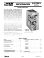
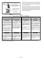
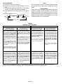
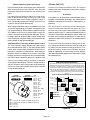
GHR32Q/V SERIES UNITS
This manual contains information pertaining to
GHR32−1 through −6 model units. GHR32 series units
are high−efficiency horizontal or down flow gas furnaces
manufactured with Lennox DuralokPlust aluminized and
stainless steel clamshell-type heat exchangers. GHR32Q
units are available in heating input capacities of 50,000 to
120,000 Btuh (14.7 to 35.2 kW) and cooling applications
from 2 through 5 tons (7.0 through 17.6 kW). GHR32V units
are available in heating capacities of 75,000 and 100,000 Btuh
(22.0 and 29.3 kW) and 3 and 5 tons (10.5 and 17.5) for cool-
ing. Refer to Engineering Handbook for proper sizing.
Units are factory equipped for use with natural gas. A kit is
available for conversion to LPG operation. GHR32−1
through −4 units are equipped with the Lennox SureLight
silicon nitride ignition system. GHR32−5 units are
equipped with the two stage (V models will have the vari-
able speed control) integrated control board. Each
GHR32 unit meets the California Nitrogen Oxides (NOx)
Standards and California Seasonal Efficiency require-
ments. The gas valve is redundant to assure safety
shut−off as required by A.G.A. and C.G.A.
The heat exchanger, burners and manifold assembly can be
removed for inspection and service. The maintenance section
gives a detailed description on how this is done.
Information contained in this manual is intended for
use by qualified service technicians only. All specifica-
tions are subject to change. Procedures outlined in this
manual are presented as a recommendation only and do
not supersede or replace local or state codes.
GHR32Q MODEL SHOWN
DOWN FLOW
POSITION
TABLE OF CONTENTS
General 1. . . . . . . . . . . . . . . . . . . . . . . . . . . . . . . . . . . . . .
Specifications Q Models 2. . . . . . . . . . . . . . . . . . . . . . . .
Blower performance Q Models 3. . . . . . . . . . . . . . . . . .
Specifications V Models 4. . . . . . . . . . . . . . . . . . . . . . . .
Blower performance V Models 5. . . . . . . . . . . . . . . . . . .
Parts Arrangement 7. . . . . . . . . . . . . . . . . . . . . . . . . . . .
I Unit Components 8. . . . . . . . . . . . . . . . . . . . . . . . . . . . .
II Placement and Installation 41. . . . . . . . . . . . . . . . . . . .
III Start Up 46. . . . . . . . . . . . . . . . . . . . . . . . . . . . . . . . . . . .
IV Heating System Service Checks 47. . . . . . . . . . . . . .
V Typical Operating Characteristics 49. . . . . . . . . . . . . .
VI Maintenance 51. . . . . . . . . . . . . . . . . . . . . . . . . . . . . . .
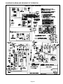
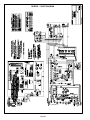
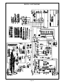
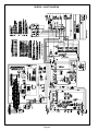
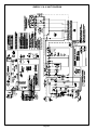
VII Wiring Diagram and Sequence of Operation 54. . . .
GHR32Q−1 54. . . . . . . . . . . . . . . . . . . . . . . . . . . . . . . .
GHR32Q−3 55. . . . . . . . . . . . . . . . . . . . . . . . . . . . . . . .
GHR32Q−5 57. . . . . . . . . . . . . . . . . . . . . . . . . . . . . . . .
GHR32V−1 59. . . . . . . . . . . . . . . . . . . . . . . . . . . . . . . .
GHR32V−3 60. . . . . . . . . . . . . . . . . . . . . . . . . . . . . . . .
GHR32V−4 61. . . . . . . . . . . . . . . . . . . . . . . . . . . . . . . .
GHR32V−5 63. . . . . . . . . . . . . . . . . . . . . . . . . . . . . . . .
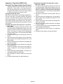
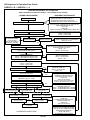
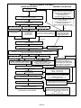
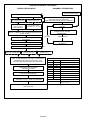
VIII Operating Flow Charts 65. . . . . . . . . . . . . . . . . . . . . .
IX Troubleshooting 76. . . . . . . . . . . . . . . . . . . . . . . . . . . .
X Blower Control Board Jumper Summary 87. . . . . . . .

Page 2
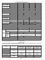
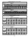
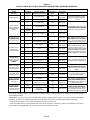
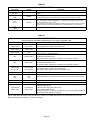
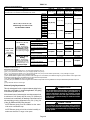
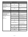
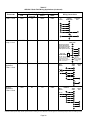
SPECIFICATIONS GHR32Q MODELS
Model No. GHR32Q2/3-50 GHR32Q3-75 GHR32Q4/5-100 GHR32Q4/5-120
Input Btuh (kW)
High Fire 50,000 (14.7) 72,000 (21.1) 100,000 (29.3) 118,000 (34.6)
I
nput
B
tu
h
(kW)
Low Fire 34,000 (10.0) 51,000 (14.9) 68,000 (19.9) 81,600 (23.9)
Output Btuh (kW)
High Fire 47,000 (13.8) 67,000 (19.6) 93,000 (27.2) 111,000 (32.5)
O
utput
B
tu
h
(kW)
Low Fire 31,600 (9.3) 47,000 (13.8) 63,000 (18.4) 75,900 (22.2)
A.F.U.E. 90.0%
California Seasonal Efficiency 83.7% 83.9% 85.3% 84.0%
Exhaust pipe connection (PVC) diameter in. (mm) 2 (51)
Intake pipe connection (PVC) diameter in. (mm) 2 (51)
Condensate drain connection (PVC) in. (mm) 1/2 (12.7)
Temperature rise High Fire 30 − 60 (17 − 33) 40 − 70 (22 − 39) 45 − 75 (25 − 42)
Temperature
rise
range _F (_C) Low Fire 25 − 55 (14 − 31) 35 − 65 (20 − 36) 40 − 70 (22 − 39)
High static certified by (A.G.A./C.G.A.) in wg. (Pa) .50 (125)
Gas Piping Size I.P.S. in. (mm) 1/2 (12.7)
Blower wheel nominal in. 10 x 8 11-1/2 x 9
Blower
wheel
nominal
diameter x width mm 254 x 203 292 x 229
Number and size of filters − in. (mm) (1) 14 x 25 x 1 (356 x 635 x 25) (1) 20 x 25 x 1 (508 x 635 x 25)
Blower motor output hp (W) 1/3 (249) 1/2 (373) 3/4 (560)
Nominal cooling Tons 2 to 3 2 to 3.5 3.5 to 5
Nominal
cooling
that can be added kW 7.0 to 10.6 7.0 to 12.3 12.3 to 17.6
Shipping weight lbs. (kg) 1 package 147 (67) 155 (70) 196 (89) 205 (93)
Electrical characteristics 120 volts 60 hertz 1 phase (less than 12 amps)
Optional Accessories (Must Be Ordered Extra)
LPG/Propane kit 59L81 (−1 and −2 models) 11M57 (−3 and later models)
Down-Flow Additive Base 32K52 32K53
Horizontal Support Frame Kit Ship. Wt. − lbs. (kg.) 56J18 18 lbs. (8 kg)
Concentric Roof/Wall Termination Kits 60G77 − For 1 1/2 inch (38 mm) venting 33K97 − For 2 inch
(51 mm) venting
60L46 − For 3 inch
(76 mm) venting
Vent/
Roof
Termination
For 2 inch (51 mm) venting 15F75 Not Available
Vent/
Intake
Termination
Kits For 3 inch (76 mm) venting Not Available 44J41
Intake
Kits
Wall
Termination
Kits
For 2 inch (51 mm) venting
15F74 (ring kit) − 22G44 (close couple) − 30G28 (WTK Close Cou-
ple)
30G79 (WTKX close couple with extension riser)
Not Available
Kit
sFor 3 inch (76 mm) venting Not Available 44J40 (close couple) 81J20 (WTK close couple)
Twinning Kit 15L38 (all models)
Condensate Drain Heat Cable 26K68 6 ft. (1.8 m) 26K69 24 ft. (7.3 m) 26K70 50 ft. (15.2 m)
Heat Cable Tape 39G04 1/2 inch (13 mm) wide or 39G03 2 inch (51 mm) wide
Annual Fuel Utilization Efficiency based on U.S. DOE test procedures and FTC labeling regulations. Isolated combustion system rating for non-weatherized furnaces.
Determine from venting tables proper intake and exhaust pipe size and termination kit required.
Cleanable polyurethane frame type filter.
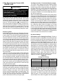
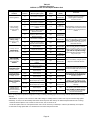
HIGH ALTITUDE
No gas pressure adjustment is needed when operating from 0 to 4500 ft. (0 to 1372m). See table below for correct manifold
pressure and prove switch for altitudes greater than 4500 ft. (1372m).
Manifold Pressure (outlet) in. w.g. (kPa)
Model No. Prove Switch 4501 to 5500 ft.
(1373 to 1676m)
5501 to 6500 ft.
(1677 to 1981m)
6501 to 7500 ft.
(1982 to 2286m)
GHR32−50 nat no change 3.5 (0.87) 3.5 (0.87) 3.5 (0.87)
GHR32−75 nat
GHR32−100 nat Kit #67K27 3.4 (0.85) 3.3 (0.82) 3.2 (0.80)
GHR32−120 L.P.
()
()
()
GHR32−50 L.P.
no change
10 0 (2 49)
10 0 (2 49)
10 0 (2 49)
GHR32−75 L.P. no c
h
ange
10
.
0
(2
.
49)
10
.
0
(2
.
49)
10
.
0
(2
.
49)
GHR32−100 L.P.
Kit #67K27
10.0 (2.49) 10.0 (2.49) 10.0 (2.49)
HGR32−120 L.P.
Ki
t
#67K27
9.6 (2.39) 9.3 (2.31) 9.0 (2.24)

Page 3
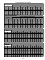
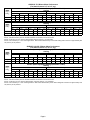
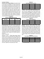
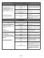
BLOWER PERFORMANCE DATA Q MODELS
GHR32Q2/3-50 BLOWER PERFORMANCE
External Static Air Volume and Motor Watts at Specific Blower Taps
External
Static
Pressure High Medium-High Medium-Low Low
in. w.g. Pa cfm L/s Watts cfm L/s Watts cfm L/s Watts cfm L/s Watts
0 0 1480 700 640 1330 630 520 1070 505 435 900 425 355
.10 25 1430 675 615 1290 610 500 1050 495 420 880 415 346
.20 50 1380 650 595 1240 585 480 1040 490 400 870 410 330
.30 75 1320 625 570 1200 565 455 1010 475 380 850 400 320
.40 100 1260 595 545 1140 540 430 980 460 370 820 385 300
.50 125 1200 565 520 1080 510 410 930 440 320 790 375 280
.60 150 1100 520 500 1000 470 385 860 405 300 740 350 265
.70 175 1000 470 470 890 420 370 750 355 290 660 310 250
.80 200 800 380 440 700 330 340 590 280 280 550 260 240
NOTE All air data is measured external to unit with air filter in place.
GHR32Q3-75 BLOWER PERFORMANCE
External Static Air Volume and Motor Watts at Specific Blower Taps
External
Static
Pressure High Medium-High Medium-Low Low
in. w.g. Pa cfm L/s Watts cfm L/s Watts cfm L/s Watts cfm L/s Watts
0 0 1650 780 720 1540 725 585 1450 685 540 1230 580 450
.10 25 1590 750 660 1490 705 550 1400 660 505 1200 565 420
.20 50 1520 715 645 1430 675 520 1350 635 485 1170 550 405
.30 75 1440 680 630 1370 645 490 1300 615 450 1130 535 390
.40 100 1370 645 610 1300 615 470 1240 585 430 1090 515 370
.50 125 1300 615 590 1240 585 450 1170 550 410 1040 490 330
.60 150 1210 570 560 1170 550 430 1100 520 375 970 460 320
.70 175 1120 530 540 1080 510 410 1020 480 350 890 420 280
.80 200 1020 480 515 980 460 380 900 425 325 750 355 260
.90 225 880 415 500 820 385 350 750 355 300 600 285 240
NOTE All air data is measured external to unit with air filter in place.
GHR32Q4/5-100 BLOWER PERFORMANCE
External Static Air Volume and Motor Watts at Specific Blower Taps
External
Static
Pressure High Medium-High Medium Medium-Low Low
in. w.g. Pa cfm L/s Watts cfm L/s Watts cfm L/s Watts cfm L/s Watts cfm L/s Watts
0 0 2530 1195 1360 2300 1085 1210 2030 960 1050 1780 840 885 1540 725 745
.10 25 2460 1160 1290 2250 1060 1140 2010 950 1010 1760 830 850 1530 720 730
.20 50 2380 1125 1270 2200 1040 1100 1990 940 990 1740 820 830 1520 715 720
.30 75 2310 1090 1250 2150 1015 1080 1950 920 970 1720 810 805 1510 715 710
.40 100 2250 1060 1200 2090 985 1060 1910 900 950 1690 800 790 1500 710 690
.50 125 2180 1030 1150 2020 955 1020 1870 880 910 1660 785 780 1480 700 670
.60 150 2100 990 1100 1960 925 980 1810 855 870 1620 765 760 1430 675 650
.70 175 2010 950 1070 1880 885 940 1750 825 855 1570 740 730 1380 650 630
.80 200 1910 900 1040 1800 850 920 1680 795 840 1500 710 710 1320 625 615
.90 225 1800 850 1010 1700 800 890 1580 745 800 1420 670 690 1240 585 600
1.00 250 1700 800 980 1600 755 870 1500 710 780 1320 625 670 1120 530 590
NOTE All air data is measured external to unit with air filter in place.
GHR32Q4/5-120 BLOWER PERFORMANCE
External Static Air Volume and Motor Watts at Specific Blower Taps
External
Static
Pressure High Medium-High Medium Medium-Low Low
in. w.g. Pa cfm L/s Watts cfm L/s Watts cfm L/s Watts cfm L/s Watts cfm L/s Watts
0 0 2400 1135 1250 2270 1070 1140 2060 970 1010 1800 850 860 1560 735 720
.10 25 2350 1110 1220 2220 1050 1100 2040 965 980 1780 840 830 1550 730 705
.20 50 2290 1080 1200 2170 1025 1080 2000 945 960 1750 825 815 1540 725 685
.30 75 2220 1050 1180 2120 1000 1060 1960 925 940 1720 810 800 1520 715 675
.40 100 2150 1015 1130 2050 965 1020 1900 895 920 1680 795 770 1500 710 660
.50 125 2080 980 1100 1980 935 980 1850 875 880 1640 775 750 1460 690 650
.60 150 2000 945 1050 1910 900 940 1780 840 840 1590 750 720 1420 670 630
.70 175 1900 895 1010 1830 865 920 1710 805 810 1530 720 690 1380 650 610
.80 200 1800 850 980 1740 820 900 1630 770 790 1460 690 675 1320 625 595
.90 225 1700 800 960 1630 770 860 1540 725 770 1380 650 660 1250 590 580
1.00 250 1600 755 940 1530 720 840 1430 675 750 1300 615 640 1150 545 560
NOTE All air data is measured external to unit with air filter in place.

Page 4
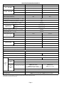
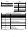
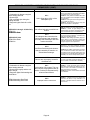
SPECIFICATIONS GHR32V MODELS
Model No. GHR32V3-75 GHR32V5-100
Inp t Bt h (kW)
High Fire 72,000 (21.1) 100,000 (29.3)
Input Btuh (kW)
Low Fire 51,000 (14.9) 68,000 (19.9)
O tp t Bt h (kW)
High Fire 67,000 (19.6) 93,000 (27.2)
Output Btuh (kW)
Low Fire 47,000 (13.8) 63,000 (18.4)
A.F.U.E. 90.0% 90.0%
California Seasonal Efficiency 83.9 85.3
Exhaust pipe connection (PVC) diameter in. (mm) 2 (51)
Intake pipe connection (PVC) diameter in. (mm) 2 (51)
Condensate drain connection (PVC) in. (mm) 1/2 (12.7)
Tem
p
erature rise High Fire 40 − 70 (22 − 39)
Temperature
rise
range _F (_C) Low Fire 35 − 65 (19 − 36)
High static certified by (A.G.A./C.G.A.) in wg. (Pa) .80 (200)
Gas Piping Size I.P.S. in. (mm) 1/2 (12.7)
Blower wheel nominal in. 10 x 8 11-1/2 x 9
Blower
wheel
nominal
diameter x width mm 254 x 203 292 x 229
Blower motor output hp (W) 1/2 (373) 1 (746)
Number and size of filters − in. (mm) (1) 14 x 25 x 1 (356 x 635 x 25) (1) 20 x 25 x 1 ( 508 x 635 x 25)
Nominal coolin
g
Tons 2 to 3.5 3.5 to 5
Nominal
cooling
that can be added kW 7.0 to 12.3 12.3 to 17.6
Shipping weight lbs. (kg) 1 package 160 (73) 201 (91)
Electrical characteristics 120 volts 60 hertz 1 phase (less than 12 amps)
Optional Accessories (Must Be Ordered Extra)
LPG/Propane kit 59L81
Down-Flow Additive Base 32K52 32K53
Horizontal Support Frame Kit Ship. Wt. − lbs. (kg.) 56J18 18 lbs. (8 kg)
Concentric Roof/Wall Termination Kits 60G77 − For 1 1/2 inch (38 mm) venting 33K97 − For 2 inch (51 mm) venting
Roof
Termination
For 2 inch (51 mm) venting 15F75
Vent/
Termination
Kits For 3 inch (76 mm) venting 44J41
Vent/
Intake
Kits
Wall
Termination
Kits
For 2 inch (51 mm) venting
15F74 (ring kit)
22G44 (close couple)
30G28 (WTK Close Couple)
30G79 (WTKX close couple w/ extension riser)
15F74 (ring kit)
22G44 (close couple)
Kits
For 3 inch (76 mm) venting 44J40 (close couple) 81J20 (WTK close couple)
Condensate Drain Heat Cable 26K68 6 ft. (1.8 m) 26K69 24 ft. (7.3 m) 26K70 50 ft. (15.2 m)
Heat Cable Tape 39G04 1/2 inch (13 mm) wide or 39G03 2 inch (51 mm) wide
Annual Fuel Utilization Efficiency based on U.S. DOE test procedures and FTC labeling regulations. Isolated combustion system rating for non-weatherized furnaces.
Determine from venting tables proper intake and exhaust pipe size and termination kit required.
Cleanable polyurethane frame type filter.

Page 5
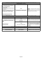
BLOWER PERFORMANCE DATA −1 through −3 V MODELS
GHR32V3-75 BLOWER PERFORMANCE
0 through 0.80 in. w.g. (0 Through 200 Pa) External Static Pressure Range
VSP2−1 Blower Control Low Speed 3
Factory Settings High Speed 4
Heat Speed 3
VSP Jumper Speed Positions
ADJUST"
Jum
p
er
LOW" Speed
(Cool, Low Heat Or Continuous Fan) HIGH" Speed (Cool) HEAT" Speed
Jumper
Setting 1 2 3 4 1 2 3 4 1 2 3 4
g
cfm L/s cfm L/s cfm L/s cfm L/s cfm L/s cfm L/s cfm L/s cfm L/s cfm L/s cfm L/s cfm L/s cfm L/s
NORM 875 415 940 445 985 465 106
0500 107
0505 1130 535 127
0600 129
0610 109
0515 1175 555 128
5605 133
0630
minus 15%
less motor
speed
750 355 795 375 850 400 915 430 900 425 940 445 105
5500 1120 530 940 445 995 470 109
5515 1180 555
NOTE The effect of static pressure and filter resistance is included in the air volumes listed.
GHR32V5-100 BLOWER PERFORMANCE
0 through 0.80 in. w.g. (0 Through 200 Pa) External Static Pressure Range
VSP2−1 Blower Control Low Speed 2
Factory Settings High Speed 4
Heat Speed 1
VSP Jumper Speed Positions
ADJUST"
Jumper
LOW" Speed (Cool Or Continuous Fan) HIGH" Speed (Cool) HEAT" Speed
Jumper
Settin
g
1 2 3 4 1 2 3 4 1 2 3 4
Setting
cfm L/s cfm L/s cfm L/s cfm L/s cfm L/s cfm L/s cfm L/s cfm L/s cfm L/s cfm L/s cfm L/s cfm L/s
NORM 1100 520 1260 595 1445 680 1635 770 1670 790 1960 925 2165 1020 2285 1075 1640 775 1825 860 2150 1015 2315 1090
minus 15%
less motor
speed
935 440 1015 480 1195 565 1355 640 1335 630 1495 705 1690 800 1800 850 1360 640 1465 690 1770 835 1905 900
NOTE The effect of static pressure and filter resistance is included in the air volumes listed.
BLOWER PERFORMANCE DATA −4 V MODELS
GHR32V3-75 BLOWER PERFORMANCE
0 through 0.80 in. w.g. (0 Through 200 Pa) External Static Pressure Range
VSP3−1 Blower Control Factory Settings ADJUST − NORM
Heat Speed − 3
Cool Speed − 4
VSP Jumper Speed Positions
ADJUST" HEAT"
ADJUST
Jumper
P iti
Low Speed High Speed
Jumper
Positions 1 2 3 4 1 2 3 4
cfm L/s cfm L/s cfm L/s cfm L/s cfm L/s cfm L/s cfm L/s cfm L/s
NORM (Normal) 875 415 940 445 985 465 1060 500 1090 515 1175 555 1285 605 1330 630
" (Minus) 15% 750 355 795 375 850 400 915 430 940 445 995 470 1095 515 1180 555
ADJUST"
COOL"
ADJUST"
Jumper
Low Speed High Speed
Jumper
P
os
i
t
i
o
n
s
1 2 3 4 1 2 3 4
Positions
cfm L/s cfm L/s cfm L/s cfm L/s cfm L/s cfm L/s cfm L/s cfm L/s
NORM (Normal) 875 415 940 445 985 465 1060 500 1070 505 1130 535 1270 600 1290 610
" (Minus) 15% 750 355 795 375 850 400 915 430 900 425 940 445 1055 500 1120 530
15% lower motor speed than NORM jumper setting.
NOTE − The effect of static pressure and filter resistance is included in air volumes shown.
NOTE − Continuous Fan only speed is approximately 825 cfm (390 L/s) − non adjustable.
NOTE − Lennox Harmony IIt zone control applications − MAX CFM is determined by COOL jumper placement with a minimum of approximately 875 cfm (415 L/s) for all positions.
GHR32V5−100 BLOWER PERFORMANCE
0 through 0.80 in. w.g. (0 Through 200 Pa) External Static Pressure Range
VSP3−1 Blower Control Factory Settings ADJUST − NORM
Heat Speed − 2
Cool Speed − 4
VSP Jumper Speed Positions
ADJUST" HEAT"
ADJUST
Jumper
P iti
Low Speed High Speed
Jumper
Positions 1 2 3 4 1 2 3 4
cfm L/s cfm L/s cfm L/s cfm L/s cfm L/s cfm L/s cfm L/s cfm L/s
NORM (Normal) 1100 520 1260 595 1445 680 1635 770 1640 775 1825 860 2150 1015 2315 1090
" (Minus) 15% 935 440 1015 480 1195 565 1355 640 1360 640 1465 690 1770 835 1905 900
ADJUST"
COOL"
ADJUST"
Jumper
Low Speed High Speed
Jumper
P
os
i
t
i
o
n
s
1 2 3 4 1 2 3 4
Positions
cfm L/s cfm L/s cfm L/s cfm L/s cfm L/s cfm L/s cfm L/s cfm L/s
NORM (Normal) 1100 520 1260 595 1445 680 1635 770 1670 790 1960 925 2165 1020 2285 1075
" (Minus) 15% 935 440 1015 480 1195 565 1355 640 1335 630 1495 705 1690 800 1800 850
15% lower motor speed than NORM jumper setting.
NOTE − The effect of static pressure and filter resistance is included in air volumes shown.
NOTE − Continuous Fan only speed is approximately 1050 cfm (495 L/s) − non adjustable.
NOTE − Lennox Harmony IIt zone control applications − MAX CFM is determined by COOL jumper placement with a minimum of approximately 1100 cfm (520 L/s) for all positions.

Page 6
GHR32V3−75−5 Blower Motor Performance
(For Static Pressure 0.0" to 0.8" w.g.)
Adjust
"
Blower Speed Adjustment Settings (Switches 5 and 6)
Cooling
Adjust
Jumper Low High
Jumper
Setting 12341234
g
cfm L/s cfm L/s cfm L/s cfm L/s cfm L/s cfm L/s cfm L/s cfm L/s
Norm 875 415 940 445 985 465 1060 500 1070 505 1130 535 1270 600 1290 610
–750 355 795 375 850 400 915 430 900 425 940 445 1055 500 1120 530
Adjust
"
Blower Speed Adjustment Settings (Switches 7 and 8)
Heating
Adj
us
t"
Jum
p
er Low High
Jumper
Setting 12341234
g
cfm L/s cfm L/s cfm L/s cfm L/s cfm L/s cfm L/s cfm L/s cfm L/s
Norm 945 446 1025 484 1125 531 1270 599 1080 510 1172 533 1286 607 1452 685
–803 379 871 411 956 451 1080 510 918 433 996 470 1093 516 1234 582
15% lower motor speed than NORM switch setting.
NOTE − The effect of static pressure and filter resistance is included in air volumes shown.
NOTE − Continuous Fan only speed is approximately 825 cfm (390 L/s) − non adjustable.
NOTE − Lennox Harmony IIt zone control applications − MAX CFM is determined by COOL switch setting with a minimum of approximately 875
cfm (415 L/s) for all positions.
GHR32V5−100/125−5 Blower Motor Performance
(For Static Pressure 0.0" to 0.8" w.g.)
Adjust
"
Blower Speed Adjustment Settings (Switches 5 and 6)
Cooling
Adj
ust
"
Jum
p
er Low High
Jumper
Setting 12341234
cfm L/s cfm L/s cfm L/s cfm L/s cfm L/s cfm L/s cfm L/s cfm L/s
Norm 1100 520 1260 595 1445 680 1635 770 1670 790 1960 925 2165 1020 2285 1075
–935 440 1015 480 1195 565 1355 640 1335 630 1495 705 1690 800 1800 850
Adjust
"
Blower Speed Adjustment Settings (Switches 7 and 8)
Heating
Adjust"
Jumper
Low High
Jumper
Setting 1* 2 3 4 1* 2 3 4
g
cfm L/s cfm L/s cfm L/s cfm L/s cfm L/s cfm L/s cfm L/s cfm L/s
Norm 1100 520 1260 595 1445 680 1635 770 1640 775 1825 860 2150 1015 2315 1090
–935 440 1015 480 1195 565 1355 640 1360 640 1465 690 1770 835 1905 900
15% lower motor speed than NORM switch setting.
NOTE − The effect of static pressure and filter resistance is included in air volumes shown.
NOTE − Continuous Fan only speed is approximately 1050 cfm (495 L/s) − non adjustable.
NOTE − Lennox Harmony IIt zone control applications − MAX CFM is determined by COOL switch setting with a minimum of approximately 1100
cfm (520 L/s) for all positions.

Page 7
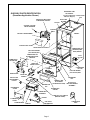
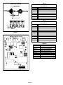
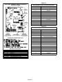
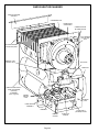
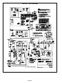
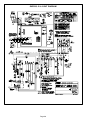
FIGURE 1
GHR32Q−5 PARTS IDENTIFICATION
(Downflow Application Shown)
TOP CAP
CABINET
PATCH PLATE
WITH BARBED
FITTING
GAS VALVE
AND MANIFOLD
BURNER BOX
COVER
FLAME SIGHT
GLASS
DuralokPlusTM
HEAT EXCHANGER
ASSEMBLY
CONDENSER
COIL
CONTROL TRANSFORMER
CONTROL
BOX
CONTROL BOX COVER
DOOR INTERLOCK SWITCH
CONTROL VOLTAGE
CIRCUIT BREAKER
HOT END HEADER
(COLLECTOR) BOX
COLD END HEADER
(COLLECTOR) BOX
COMBUSTION
AIR INDUCER
COMBUSTION AIR
PROVING (PRES-
SURE) SWITCH
PRIMARY LIMIT
AUTO−RESET
(ALTERNATE STYLES)
SUPPLY AIR
BLOWER
BURNER BOX
ASSEMBLY
FRESH AIR
INTAKE FITTING
BURNER BOX
GASKET
BURNER BOX
TOP
FLAME SENSOR
EXHAUST TEE
COMBUSTION AIR
BLOWER MOUNTING
BRACKET
CORBELS
INTAKE AIR
GASKET
FLUE
COLLAR
CONDENSATE
COLLAR
FLAME ROLL−OUT SWITCH
(MANUAL RESET)
BACK FILTER
CLIP
SECONDARY LIMIT
AUTO−RESET
(Located on Backside
of Blower Wrapper)
GASKET
ORIFICE
CONDENSATE
TRAP
IGNITOR
SURELIGHT TWO−STAGE
INTEGRATED CONTROL

BLACK
WHITE
NEUTRAL
BROWN
J96
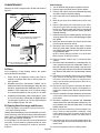
INSTALLING BROWN
ACCESSORY WIRE TO J96
FIGURE 5
Page 8
I−UNIT COMPONENTS
GHR32 unit components are shown in figure 1. The com-
bustion air blower, gas valve and burners can be accessed
by removing the burner access panel. The blower and con-
trol box can be accessed by removing the blower access
door.
WARNING
Before attempting to perform any service or mainte-
nance, turn the electrical power to unit OFF at dis-
connect switch
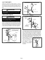
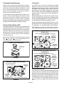
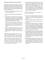
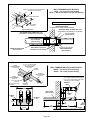
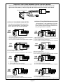
A−Make-Up Box (Figure 2)
WARNING
Unit must be grounded in accordance with national
and local codes. Electric Shock Hazaed.
Can cause injury or death.
A field make−up box (see figure 2) is provided for line voltage
wiring. Line voltage wiring to unit is done through the J96 jack
from the field make−up box to plug P96 from the control box.
The box may be installed inside or outside the unit (see figures
3 and 4) and may be installed on the unit left or right side.
FIGURE 2
MAKE-UP BOX
BOX
COVER
JACK J96
POWER ENTRY KNOCKOUT
120V LINE VOLTAGE
PIGTAIL CONNECTIONS
UNIT
GROUND
Box may be installed inside or outside unit.
FIGURE 3
INTERIOR MAKE−UP BOX INSTALLATION
J96
MAKE−UP
BOX
BUSHING P96
FIGURE 4
EXTERIOR MAKE−UP BOX INSTALLATION
P96
J96
(Shown with
accessory
wire connected)
MAKE−UP
BOX
BUSHING
An accessory (brown) output wire is provided with the make-
up box. The wire provides a 120V connection for optional ac-
cessories such as electronic air cleaner or humidifier. If
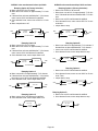
used, the wire is field installed in J96 jack plug by inserting the
pin of the brown wire into the open socket of the jack. See fig-
ure 5. 120V accessories rated up to 4 amps total may be con-
nected to this wire. The neutral
leg of the accessory is con-
nected to the neutral white wire
in the make-up box. The acces-
sory terminal is energized
whenever the indoor blower is
in operation.

Page 9
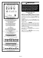
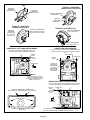
B−Control Box (Figure 6)
CAUTION
Electrostatic discharge can affect electronic
components. Take precautions during furnace
installation and service to protect the furnace’s
electronic controls. Precautions will help to avoid
control exposure to electrostatic discharge by
putting the furnace, the control and the techni-
cian at the same electrostatic potential. Neutral-
ize electrostatic charge by touching hand and all
tools on an unpainted unit surface, such as the
gas valve or blower deck, before performing any
service procedure.
ELECTROSTATIC DISCHARGE (ESD)
Precautions and Procedures
GHR32−1 through −4 CONTROL BOX
FIGURE 6
CIRCUIT
BREAKER
VSP−2
CONTROL
(v models only)
TWO−STAGE
CONTROL
SURELIGHT
CONTROL
TRANSFORMER
DOOR INTERLOCK
SWITCH
Unit transformer (T1), circuit breaker (CB8), SureLight
control (A92), VSP−2 control (A24) and Two−stage control
(A86) are located in the control box. In addition, a door in-
terlock switch (S51) is located in the control box. Jackplugs
and a snap-off" terminal strip allow the control box to be
easily removed for blower service.
1. Control Transformer (T1)
A transformer located in the control box provides power to
the low voltage 24 volt section of the unit. Transformers on
all models are rated 40VA with a 120V primary and a 24V
secondary.
2. Circuit Breaker (CB8)
A 24V circuit breaker is also located in the control box. The
switch provides overcurrent protection to the transformer
(T1). The breaker is rated 3 amps at 32V. If the current ex-
ceeds this limit the breaker will trip and all unit operation will
shut down. The breaker can be manually reset by pressing the
button on the face (figure 7).
FIGURE 7
CIRCUIT BREAKER CB8
PRESS TO RESET
3.Door Interlock Switch (S51)
A door interlock switch rated 14 amps at 125VAC is located
on the control box. The switch is wired in series with line
voltage. When the blower door is removed the unit will shut
down.
DANGER
Shock hazard.
Disconnect power before servicing. Control is not
field repairable. If control is inoperable, simply
replace entire control.
Can cause injury or death. Unsafe operation will
result if repair is attempted.
4. SureLight Ignition System A92
All GHR32−1 through −4 units are equipped with the Len-
nox SureLight ignition system. The system consists of ig-
nitor (figure 8) and ignition control board (figure 9 and
table 3 ). The board and ignitor work in combination to en-
sure furnace ignition and ignitor durability. The SureLight
integrated board controls all major furnace operations.
Table 1 and 2 show jack plug terminal designations. shows
control board terminations. The board also features two
LED lights for troubleshooting and two accessory termi-
nals rated at (1) one amp. See table 4 for troubleshooting
diagnostic codes. Units equipped with the SureLight
board can be used with either electronic or electro−me-
chanical thermostats without modification. The SureLight
ignitor is made of durable silicon nitride. Ignitor longevity
is also enhanced by voltage ramping by the control board.
The board finds the lowest ignitor temperature which will
successfully light the burner, thus increasing the life of the
ignitor.
NOTE − Do not remove blower access panel to read
Surelight LED lights. A sight glass is provided on the
access panel for viewing.

Page 10
FIGURE 8
SURELIGHT IGNITOR
13/32’
5/8" MEASUREMENT IS TO I.D.
OF RETENTION RING
5/16"
FRONT VIEW
TOP VIEW
FIGURE 9
SURELIGHT INTEGRATED CONTROL BOARD
GHR32−1 through −4 units
TABLE 1
SureLight BOARD J156 (J2) TERMINAL
DESIGNATIONS
PIN # FUNCTION
1 Ignitor
2Not Used
3Ignitor Neutral
4Combustion Air Blower Line Voltage
5Not Used
6Combustion Air Blower Neutral
TABLE 2
SureLight BOARD J58 (J1) TERMINAL
DESIGNATIONS
PIN # FUNCTION
1Primary Limit In
2Gas Valve Common
3Roll Out Switch Out
4Gas Valve 24V
5Pressure Switch In
6Pressure Switch and Primary Limit Out
7Not Used
8Roll Out Switch In
9Ground
TERMINAL DESIGNATIONS
ACB COOL
ACB HEAT
PARK
ACB LOW
ACC
TX
HOT
HTG ACC
NEUTRALS
24VAC HOT
24VAC RTN
FLAME SENSE
Blower − Cooling Speed (Line Volt)
Blower − Heating Speed (Line Volt)
Alternate Blower Speeds (Dead)
Continuous Low Speed Blower
Accessory Terminal (Line Volt)
120VAC Hot to Transformer
120VAC Hot Input
Heat Only Accessory (Line Volt)
120VAC Neutrals
24VAC Hot from Transformer
24VAC Return from Transformer
Flame Sense Terminal
TABLE 3

Page 11
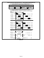
TABLE 4
DIAGNOSTIC CODES
MAKE SURE TO ID LED’S CORRECTLY: REFER TO INSTALLATION INSTRUCTIONS FOR CONTROL BOARD LAYOUT.
LED #1 LED #2 DESCRIPTION
SIMULTANEOUS
SLOW FLASH
SIMULTANEOUS
SLOW FLASH
Power − Normal operation
Also signaled during cooling and continuous fan.
SIMULTANEOUS FAST
FLASH
SIMULTANEOUS FAST
FLASH Normal operation − signaled when heating demand initiated at thermostat.
SLOW FLASH ON Primary or Secondary limit open. Limit must close within 3 minutes or board goes
into one hour limit Watchguard.
OFF SLOW FLASH
Watchguard pressure switch − 5 minutes. Pressure switch open or has opened 5
times during a single call for heat; OR: Blocked inlet/exhaust vent; OR: Conden-
sate line blocked; OR: Pressure switch closed prior to activation of combustion
air blower.
ALTERNATING SLOW
FLASH
ALTERNATING SLOW
FLASH Watchguard 60 minute delay − burners fail to ignite.
SLOW FLASH OFF Flame sensed without gas valve energized.
ON SLOW FLASH Rollout switch open. OR: 9 pin connector improperly attached.
ON
ON
OFF
ON
OFF
ON
Circuit board failure or control wired incorrectly.
FAST FLASH SLOW FLASH Main power polarity reversed. Switch line and neutral.
SLOW FLASH FAST FLASH Low flame signal. Measures below .61 microAmps. Replace flame sense rod.
ALTERNATING FAST
FLASH
ALTERNATING FAST
FLASH
Improper main ground or line voltage below 75 volts; OR: Broken ignitor; OR:
Open ignitor circuit.
NOTE − Slow flash equals 1 Hz (one flash per second). Fast flash equals 3 Hz (three flashes per second). Drop out flame sense current < 0.21 microAmps
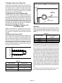
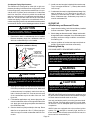
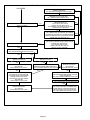
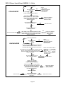
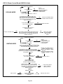
a−Electronic Ignition Figures 12 and 13
On a call for heat the SureLight control monitors the com-
bustion air blower pressure switch. The control will not be-
gin the heating cycle if the pressure switch is closed (by−
passed). Once the pressure switch is determined to be
open, the combustion air blower is energized. When the
differential in the pressure switch is great enough, the pres-
sure switch closes and a 15−second pre−purge begins. If
the pressure switch is not proven within 2−1/2 minutes, the
control goes into Watchguard−Pressure Switch mode for a
5−minute re−set period.
After the 15−second pre−purge period, the SureLight ignitor
warms up for 20 seconds after which the gas valve opens
for a 4−second trial for ignition. Units with control 97L48: ig-
nitor stays energized during the trial or until flame is
sensed. Units with control 56L83: ignitor stays energized
for the first second of the 4−second trial. If ignition is not
proved during the 4−second period, the control (97L48 or
56L83) will try four more times with an inter purge and
warm−up time between trials of 35 seconds. After a total of
five trials for ignition (including the initial trial), the control
goes into Watchguard−Flame Failure mode. After a 60−min-
ute reset period, the control will begin the ignition sequence
again.
The SureLight control board has an added feature that pro-
longs the life of the ignitor. After a successful ignition, the
SureLight control utilizes less power to energize the ignitor
on successive calls for heat. The control continues to ramp
down the voltage to the ignitor until it finds the lowest
amount of power that will provide a successful ignition. This
amount of power is used for 255 cycles. On the 256th call
for heat, the control will again ramp down until the lowest
power is determined and the cycle begins again.
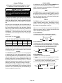
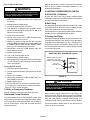
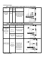
b−Fan Time Control Q Models Only
The fan on time of 45 seconds is not adjustable. Fan off
time (time that the blower operates after the heat demand
has been satisfied) can be adjusted by flipping the dip
switches located on the SureLight integrated control. The
unit is shipped with a factory fan off setting of 90 seconds.
Fan off time will affect comfort and is adjustable to satisfy
individual applications. See figure 10.
FIGURE 10
FAN-OFF TIME ADJUSTMENT
To adjust fan−off timing, flip dip switch to desired setting.
60sec. 90sec. 120sec. 180sec.

Page 12
c−Flame Sensor
A flame sensor is located on the left side of the burner sup-
port. See figure 11. The sensor is mounted on a bracket in
the burner support and the tip protrudes into the flame en-
velope of the left−most burner. The sensor is fastened to
burner supports and can be removed for service without re-
moving any part of the burners. During operation, flame is
sensed by current passed through the flame and sensing
electrode. The SureLight control allows the gas valve to re-
main open as long as flame signal is sensed.
FIGURE 11
SENSOR IGNITOR
3/8"
NOTE − The GHR32 furnace contains electronic com-
ponents that are polarity sensitive. Make sure that the
furnace is wired correctly and is properly grounded.
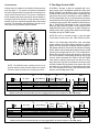
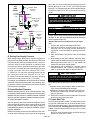
5. Two−Stage Control (A86)
All GHR32−1 through −4 units are equipped with a two−
stage control board. Two different boards have been used.
Boards 43K9001 and 29M9201 (figure 14) are identical,
except the 9 pin connector on 43K9001 is replaced by two
relays with quick connect terminals on board 29M9201.
The two−stage board acts as a go between from the indoor
thermostat to the SureLight ignition board. The board can
be utilized in three modes: with a SINGLE−STAGE thermo-
stat, a TWO−STAGE thermostat or with a second−stage
(high fire) delay called W2 TIMED. The two−stage board is
equipped with a jumper (see figure 14) which changes op-
erating modes and a jumper which adjusts second−stage
heat delay during W2 TIMED mode.
NOTE−The mode of operation jumper on the two−stage
control board is factory set in the TWO−STAGE" position.
While in the single−stage thermostat mode (one−stage
jumper setting), the unit will always operate on second−
stage heat. The combustion air blower (B6) will operate on
high speed and indoor blower (B3) will operate on heating
speed. While in the two−stage thermostat mode the unit will
operate on first−stage heat (low fire). The combustion air
blower (B6) and indoor blower will operate on low speed.
The unit will switch to second−stage heat (high fire) on call
from the indoor thermostat W2. While in the W2 TIMED
mode (factory setting 8 minutes) the unit will fire on first−
stage heat (low fire) with the combustion air blower (B6)
and indoor blower (B3) operating on low speed. After a set
time delay the unit switches to second−stage heat (high
fire). The combustion air blower and indoor blower also
switch to second−stage heat mode.
DEMAND
CAB
GAS VALVE
15
ON
OFF
38
IGNITOR
341
Pre −Purge Ignitor Warmup Trial for
Ignition
Post
Purge
5 SEC80
*Blower on time will be 45 seconds after gas valve is energized. Blower off time will depend on OFF TIME" Setting.
INDOOR BLOWER
FIGURE 12
Blower On"
Delay
SureLight Control Ignition Sequence Board 56L8301
35
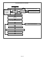
DEMAND
CAB
GAS VALVE
15
ON
OFF
38
IGNITOR
341
Pre −Purge Ignitor Warmup Trial for
Ignition Post
Purge
5 SEC80
*Blower on time will be 45 seconds after gas valve is energized. Blower off time will depend on OFF TIME" Setting.
INDOOR BLOWER
FIGURE 13
Blower On"
Delay
SureLight Control Ignition Sequence Board 97L4801

Page 13
TWO−STAGE CONTROL BOARD
G32(V) −1 through −4 units
FIGURE 14
W2 TIMED
DELAY JUMPER
MODE OF
OPERATION
JUMPER
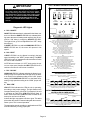
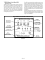
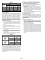
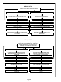
6.VSP2−1 Blower Control Board (A24)
−1 through −3 V Models only
GHR32V−1 through −3 units are equipped with a variable
speed motor that is capable of maintaining a specified CFM
throughout the external static range. The unit uses the
VSP2−1 variable speed control board, located in the blow-
er compartment, which controls the blower speed and
provides diagnostic LEDs. The control has a non−adjust-
able, factory preset ON" fan timing delay and an adjustable
OFF" fan timing delay (see figure 17).
The VSP2−1 also senses limit trip condition and turns on the
blower. The GHR32 primary limit switch is located in the
middle of the vestibule wall and the secondary limit switch is
located int ehblower compartment. When excess heat is
sensed in the heat exchanger, or blower compartment,
the respective switch will open and interrupt the current to
the gas valve, while at the same time the VSP2−1 energizes
the blower on heating speed. The limit automatically resets
when the unit temperature returns to normal and the blower is
de−energized.
Diagnostic LEDs located on the VSP2−1 control board are pro-
vided to aid in identifying the unit’s mode of operation. Certain
scenarios will arise depending on the jumper positions. Refer
to figure 15 for identification.
JP
2
HIGH LOW ADJUST HEAT
CFM
HI/LOW
ON/OFF
HEAT
HTG.
BLOWER
12 DS2
DS3
DS1
DS4
1
2
3
4
1
2
3
4
1
2
3
4
TEST
−
+
NORM
210
150
90
270
JP
1
VSP2−1 VARIABLE SPEED CONTROL BOARD SELECTIONS
FIGURE 15
DIAGNOSTIC
DS LEDS
FAN OFF"
TIMING PINS
JP46
13 PIN PLUG
(BOARD TO MOTOR)
HEATING STAGE
JUMPER SELECTOR PINS
JP73
15 PIN PLUG
(BOARD TO VARIOUS
POINTS IN FURNACE)
HIGH SPEED
SELECTOR PINS
(COOLING ONLY)
LOW SPEED
SELECTOR PINS
(COOLING, HEATING and
CONTINUOUS FAN)
HEATING SPEED
SELECTOR PINS
OPERATIONAL
SELECTOR PINS
(Affects both heating and
cooling modes)
1
1
See table 5 for VSP2
factory settings

Page 14
IMPORTANT
24 VAC half wave rectified (DC pulse), when mea-
sured with a meter, may appear as a lower or higher
voltage depending on the make of the meter. Rather
than attempting to measure the output voltage of the
VSP2 board, see GHR32 BLOWER & VSP2 BLOWER
CONTROL BOARD TROUBLESHOOTING FLOW
CHART in the TROUBLESHOOTING section of this
manual.
Diagnostic LED Lights
a − DS3 ON/OFF"
ON/OFF−DS3 indicates there is a demand for the blower mo-
tor to run. When the ON/OFF LED−DS3 is lit, a demand is be-
ing sent to the motor. In heating mode only, there is a 45 sec-
ond fan ON" delay in energizing ON/OFF LED−DS3.
The light will not go off until adjustable fan OFF" delay
has expired.
If ON/OFF LED−DS3 is on and both HIGH/LOW LED−DS1 &
HEAT LED−DS2 are off, the motor will operate in low
speed.
b − DS2 HEAT"
If HEAT LED−DS2 is on, the blower is running in the heat
speed according to the HEAT" jumper setting. The HEAT
LED−DS2 comes on instantaneous and switches off when
the call for heat is satisfied.
NOTE−When the blower is in OFF" delay mode, the mo-
tor runs at low speed, therefore the HEAT LED−DS2 is off. It
switches off when the call for heat is satisfied.
c − DS1 HI/LOW"
HIGH/LOW LED−DS1 indicates whether the blower is op-
erating in high or low speed. When the light is off, the blow-
er is running in low speed according to the LOW" jumper
setting. When HIGH/LOW LED−DS1 is on, the blower is op-
erating in high speed according to the HIGH" jumper set-
ting.
d − DS4 CFM"
CFM LED−DS4 indicates the CFM the unit is operating,
according to the jumper settings. The light flashes once
for approximately every 100 CFM. For example, if the unit
is operating at 1000 CFM, CFM LED−DS4 will flash 10
times. If the CFM is 2050, CFM LED−DS4 will flash 20 full
times plus one fast or half flash.
At times the light may appear to flicker or glow. This takes
place when the control is communicating with the motor be-
tween cycles. This is normal operation.
The appropriate speed according to application and CFM
need is selected by moving jumper pins. FIGURE 16
VOLTAGES INTO VSP2−1
VOLTAGES FROM VSP2−1 TO ELECTRONICALLY
CONTROLLED BLOWER MOTOR
34 volts
−34 volts
0 volts
Voltage across J73 pins 13 to 1 and 6 to 1 is 24VAC as shown here.
Refer to unit wiring diagram.
Voltage across J46 pins 6 to 3 and 1 to 3 is half-rectified AC as shown here.
Refer to unit wiring diagram.
Voltage across J73 pins 4 to 1 is approximately 15-20VDC (straight voltage) if CCB
is used. If Harmony is used a voltage of 0−25VDC should be present.
If CCB or Harmony is not used, pin 4 to 1 voltage is 21VAC.
Approx.
34 volts
0 volts
Voltage across J46 pins 8 and 9 to 3, is approximately 15-20VDC if CCB is used. If CCB or
Harmony is not used, pins 8 and 9 to 3 voltage is approximately 21VAC. If Harmony is used
a voltage of 0−25VDC should be present.
24VAC @ 60Hz.
24VAC Half-Rectified (DC Pulse)
@ 60Hz.
J46
HIGH LOW ADJUST HEAT
CFM
HI/LOW
ON/OFF
HEAT
HTG.
BLOWER
12 DS2
DS3
DS1
DS4
1
2
3
4
1
2
3
4
1
2
3
4
TEST
−
+
NORM
210
150
90
270
J73
1
1
J73
PIN 1 - C - 24 VAC common.
PIN 2 - G - Input signal from thermostat’s fan signal.
PIN 3 - W2 - Input signal for second stage heat from the thermostat.
PIN 4 - DS - Input signal for the blower speed regulation.
PIN 5 - Limit - Input signal from the external limit.
PIN 6 - R - 24 VAC power to the thermostat.
PIN 7 - C - 24 VAC common.
Pin 8 - C - 24 VAC common.
PIN 9 - CI - Input signal from the fan limit control.
PIN 10 - CO - Output signal to the burner control.
PIN 11 - HT - Input signal from the fan limit control.
PIN 12 - ACC - 24 VAC accessory output.
PIN 13 - 24V - Input 24 VAC power for the VSP2-1.
PIN 14 - 24V - Input 24 VAC power for the VSP2-1.
PIN 15 - V - Input signal from the gas line.
J46
PIN 1 - Heat - Heat speed input signal to the ICM2 motor.
PIN 2 - C - 24 VAC common.
PIN 3 - C - 24 VAC common.
PIN 4 - High Tap - High Speed programming input.
PIN 5 - Low Tap - Low speed programming input.
PIN 6 - On / Off - On / off output signal to the ICM2 motor.
PIN 7 - Adjust Tap - ICM2 mode selection.
PIN 8 - Hi / Low - Speed regulate input signal to the ICM2 motor.
PIN 9 - Hi / Low - Speed regulate input signal to the ICM2 motor.
PIN 10 - Ref. V - ICM2 reference voltage.
PIN 11 - Heat Tap - Heating blower speed programming.
PIN 12 - C - 24 VAC common.
PIN 13 - cfm - Motor speed diagnostic signal.
VSP2−1 BLOWER CONTROL BOARD (A24)

Page 15
NOTE−On Harmony II zoning applications in the heating
mode, the highest speed obtainable is the same as the highest
cooling speed selection. Also, the heating speed (heat jumper
position) is only used when the primary limit has been tripped.
In non−zoning applications, refer to the section on the VSP2−1
control.
Jumper Settings
SEE BLOWER PERFORMANCE TABLES AT FRONT
OF MANUAL FOR ANY REFERENCE TO CFM.
IMPORTANT
Before changing jumper setting, make sure the
motor has completely stopped. Any jumper set-
ting change will not take place while the motor
is running.
To change jumper positions, gently pull the jumper off the pins
and place it on the desired set of pins. The following section
outlines the different jumper selections available and condi-
tions associated with each one. Refer to figure 15 for identifica-
tion.
After the CFM for each application has been determined, the
jumper settings must be adjusted to reflect those given in
the tables in the blower performance section. Using the tables,
determine which row of CFM volumes most closely
matches the desired CFM. Once a specific row has been
chosen (NORMAL or −), CFM volumes from other rows
cannot be used. Below are the descriptions of each of the
jumper selections.
Refer to table 5 for factory settings. Refer to the blower perfor-
mance tables for the approximate air volume for each setting.
TABLE 5
VSP2−1 FACTORY SETTINGS
MODEL HIGH LOW ADJUST HEAT
GHR32V−75−
1, −2, −3 units 4 3 NORM 2
GHR32V−100
−1, −2, −3
units
4 2 NORM 1
a−ADJUST"
The ADJUST pins allow the motor to run at normal speed or
approximately 15% lower than normal speed. The blower
performance tables give two rows (NORMAL and −) with
their respective CFM volumes. The + adjustment setting is
not operable. Notice in the GHR32V5−100 table, that the
normal adjustment setting for heat speed position #3 is
2150 CFM (1015L/s). After the adjustment setting has been
determined, chose the remaining speed jumper settings
from those offered in the table.
The TEST pin is available to bypass the VSP2−1 control and
run the motor at approximately 70% to test that the motor is
operational. This is beneficial primarily in troubleshoot-
ing. G must be energized for motor to run.
b−HEATING BLOWER"
For GHRV32 units, place the HEATING BLOWER jumper
across the second and third pins (position #2).
When W1 is energized, the LOW jumper selections are ac-
tivated. The HEAT jumper selections are activated when
W2 is energized.
NOTE−In Harmony II zoning applications, HEATING
BLOWER jumper must be in position #2.
c−HEAT"
The HEAT jumper is used to set the blower speed to ob-
tain the required CFM as outlined in HEAT SPEED in the
blower performance tables.
The HEAT jumper selections are activated with a call for
second-stage heating (W2).
d−HIGH"
The HIGH jumper is used to determine the CFM during
cooling speed. These jumper selections are activated
when G and DS terminals are energized.
e−LOW"
The LOW jumper is used to determine CFM during low
speed cooling. These jumper selections are activated
when G is energized. The LOW jumper may also be used for
low speed heating. See the HEAT" section for details.
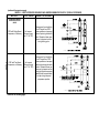
f−FAN OFF"
Fan OFF" timings (time that the blower operates after the
heat demand has been satisfied) are determined by the ar-
rangement of a jumper on the VSP2−1 board. See figure
17. To adjust fan OFF" timings, gently disconnect the
jumper and reposition it across pins corresponding with the
new timing. Fan OFF" time is adjustable from 90 to 330
seconds. The control has a non−adjustable, factory preset
on" fan timing (45 seconds).
WARNING − MAKE SURE TO DISCONNECT POWER
BEFORE CHANGING FAN OFF" TIMINGS.

Page 16
FIGURE 17
FAN-OFF TIME ADJUSTMENT
270 210
150 90
To adjust fan−off timings:
Remove jumper from VSP2−1 and select
one of the other pin combinations to
achieve the desired time.
TIMING
JUMPER
TIMING PINS (seconds)
Leave jumper off to achieve
330 second fan−off timing.
Fan-off timing is factory
set at 90 seconds
NOTEIf fan OFF" time is too low, residual heat in heat
exchanger may cause primary limit S10 to trip resulting
in frequent cycling of blower. If this occurs, adjust blow-
er to longer time setting.
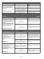
Table 6 outlines the operation of the variable speed motor
in relation to specific modes of operation. Some informa-
tion has been repeated from the previous section to provide
an example. Refer to each diagnostic LED or jumper settings
section for more information.
TABLE 6
VSP2−1 GHR32−1 through −3 units OPERATION
HEATING MODE COOLING MODE
UNITS WITH
SINGLE−STAGE HEATING
UNITS WITH
TWO−STAGE HEATING
UNITS WITH SINGLE−
SPEED COMPRESSOR
UNITS WITH TWO−SPEED
COMPRESSOR
NON−ZONED
APPLICATIONS
Using a single−stage thermostat with
one−stage" heating, the HEAT LED−
DS2 is lit when the thermostat calls for
heat. The ON/OFF LED−DS3 is lit after
110 seconds (65 seconds pre−purge
and 45 seconds fan ON" time) from
the time a call for heat is made. This in-
dicates the blower is operating in heat-
ing speed.
Using a single−stage thermostat with
W2 TIMED," and W1 calling, the ON/
OFF LED−DS3 is lit to indicate the
blower is operating on low speed.
When the HEAT LED−DS2 is lit, the
blower is operating in heating speed,
and second−stage (W2) heating is call-
ing.
NON−ZONED
APPLICATIONS
Using a two−stage thermostat with
first−stage (W1) calling, the ON/OFF
LED−DS3 is lit to indicate the blower is
operating in low speed.
When the ON/OFF LED−DS3 and
HEAT LED−DS2 are lit, the blower is
operating in heating speed and sec-
ond−stage (W2) heating is calling.
HEAT LED−DS2 is lit with a call for heat
from the thermostat. ON/OFF LED−
DS3 is lit after 110 seconds from the
time a call for heat is made.
NON−ZONED
APPLICATIONS
The terminals DS and Y must be
jumpered together. With a call for
cooling, terminals G, Y and DS on the
unit control board are energized from
the thermostat. HI/LOW LED−DS1
and ON/OFF LED−DS3 are lit to indi-
cate the blower is operating on high
speed.
NOTEY and DS are factory jump-
ered for single−stage cooling, non−
zoned applications.
NOTEFor low speed during single−
stage cooling remove jumper from Y
to DS.
NON−ZONED
APPLICATIONS
The ON/OFF LED−DS3 is lit to indicate
the blower is operating in first stage
cooling. This LED is energized on
when a 24VAC thermostat demand is
supplied to the control (terminal G" on
the control board terminal strip).
In second stage, the ON/OFF LED−
DS3 and HI/LOW LED−DS1 are lit to
indicate the blower is operating on
high speed (24VAC is supplied to the
unit terminal strip Y2 from Y2 on the
thermostat).
NOTE Jumper must be moved from
Y1 to Y2 In two−speed, non−zoned ap-
plications.
HARMONY ZONED
APPLICATIONS
The blower speed is controlled by the
PWM (pulse width modulation) signal
sent from the control center of the zon-
ing system to the terminal strip’s DS
terminal. HI/LOW LED−DS1 and ON/
OFF LED−DS3 are lit to indicate the
blower is operating.
NOTE−In Harmony II zoning applica-
tions, HTG. BLOWER jumper must be
in position #2.
HARMONY ZONED
APPLICATIONS
The blower speed is controlled by the
PWM (pulse width modulation) signal
sent from the control center of the
zoning system to the terminal strip’s
DS terminal. HI/LOW LED−DS1 and
ON/OFF LED−DS3 are lit to indicate
the blower is operating.
HARMONY ZONED
APPLICATIONS
The blower speed is controlled by the
PWM (pulse width modulation) signal
sent from the control center of the zon-
ing system to the terminal strip’s DS
terminal. HI/LOW LED−DS1 and ON/
OFF LED−DS3 are lit to indicate the
blower is operating.
NOTE: For zone applications with Harmony, remove the wire from the pin #3 of the J73 terminal on the VSP control board, insulate the
end, and secure it to prevent from shorting.

Page 17
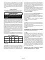
7.VSP3−1 Blower Control Board (A24)
GHR32V−4 Units
GHR32V−4 units are equipped with a variable speed motor
that is capable of maintaining a specified CFM throughout
the external static range. The unit uses the VSP3−1 vari-
able speed control board, located in the blower compart-
ment, which controls the blower speed and provides
diagnostic LEDs. The control has both a non−adjustable,
factory preset ON" fan timing delay and an adjustable OFF"
fan timing delay (see figure 17).
The VSP3−1 also senses limit trip condition and turns on the
blower. The GHR32V limit switch is located in the middle of the
vestibule wall. When excess heat is sensed in the heat ex-
changer, the limit switch will open and interrupt the current
to the gas valve, while at the same time the VSP3−1 energizes
the blower on heating speed. The limit automatically resets
when the unit temperature returns to normal and the blower is
de−energized.
Diagnostic LEDs located on the VSP3−1 control board are pro-
vided to aid in identifying the unit’s mode of operation. Certain
scenarios will arise depending on the jumper positions. Refer
to figure 18 for identification.
JP2
DELAY COOL ADJUST HEAT
CFM
HI/LOW
ON/OFF
HEAT
HTG.
BLOWER
12 DS2
DS3
DS1
DS4
1
2
3
4
1
2
3
4
1
2
3
4
TEST
−
+
NORM
210
150
90
270
JP1
VSP3−1 VARIABLE SPEED CONTROL BOARD SELECTIONS
DIAGNOSTIC
DS LEDS
FAN OFF"
TIMING PINS
JP46
13 PIN PLUG
(BOARD TO MOTOR)
HEATING STAGE
JUMPER SELECTOR PINS
JP73
15 PIN PLUG
(BOARD TO VARIOUS
POINTS IN FURNACE)
DELAY PROFILE
SELECTOR PINS
(COOLING ONLY)
COOL SPEED
SELECTOR PINS
(COOLING, HEATING and
CONTINUOUS FAN)
HEATING SPEED
SELECTOR PINS
OPERATIONAL
SELECTOR PINS
(Affects both heating
and cooling modes)
1
1
See table 7 for VSP3−1
factory settings
FIGURE 18

Page 18
VSP3−1 BLOWER CONTROL BOARD (A24)
VOLTAGES INTO VSP3−1
VOLTAGES FROM VSP3−1 TO ELECTRONICALLY
CONTROLLED BLOWER MOTOR
34 volts
−34 volts
0
volts
Voltage across J73 pins 13 to 1 and 6 to 1 is 24VAC as shown here.
Refer to unit wiring diagram.
Voltage across J46 pins 6 to 3 and 1 to 3 is half-rectified AC as shown here.
Refer to unit wiring diagram.
Voltage across J73 pins 4 to 1 is approximately 15-20VDC (straight voltage)
if CCB is used. If Harmony is used a voltage of 0−25VDC should be present.
If CCB or Harmony is not used, pin 4 to 1 voltage is 21VAC.
Approx.
34 volts
0
volts
Voltage across J46 pin 9 to 3 is approximately 15-20VDC if CCB is used. If CCB or
Harmony is not used, pin 9 to 3 voltage is approximately 21VAC. If Harmony is used
a voltage of 0−25VDC should be present.
24VAC @ 60Hz.
24VAC Half-Rectified (DC
Pulse)
@ 60Hz.
J46
DELAY COOL ADJUST HEAT
CFM
HI/LOW
ON/OFF
HEAT
HTG.
BLOWER
12 DS2
DS3
DS1
DS4
1
2
3
4
1
2
3
4
1
2
3
4
TEST
−
+
NORM
210
150
90
270
J73
1
1
J73
PIN 1 - C - 24 VAC common.
PIN 2 - G - Input signal from thermostat’s fan signal.
PIN 3 - W2 - Input signal for second stage heat from the thermostat.
PIN 4 - DS - Input signal for the blower speed regulation.
PIN 5 - Limit - Input signal from the external limit.
PIN 6 - R - 24 VAC power to the thermostat.
PIN 7 - C - 24 VAC common.
Pin 8 - C - 24 VAC common.
PIN 9 - CI - Input signal from the fan limit control.
PIN 10 - CO - Output signal to the burner control.
PIN 11 - HT - Input signal from the fan limit control.
PIN 12 - ACC - 24 VAC accessory output.
PIN 13 - 24V - Input 24 VAC power for the VSP2-1.
PIN 14 - 24V - Input 24 VAC power for the VSP2-1.
PIN 15 - V - Input signal from the gas line.
J46
PIN 1 - Not Used.
PIN 2 - C - 24 VAC common.
PIN 3 - C - 24 VAC common.
PIN 4 - Delay Tap - Delay profile programming input.
PIN 5 - Cooling blower speed programming input.
PIN 6 - On / Off - On / off output signal to the ICM2 motor.
PIN 7 - Adjust Tap - ICM2 mode selection.
PIN 8 - NOT USED
PIN 9 - Hi / Low - Speed regulate input signal to the ICM2 motor with CCB1 and
HARMONY only
PIN 10 - Ref. V - ICM2 reference voltage.
PIN 11 - Heat Tap - Heating blower speed programming.
PIN 12 - C - 24 VAC common.
PIN 13 - cfm - Motor speed diagnostic signal.
FIGURE 19
IMPORTANT
24 VAC half wave rectified (DC pulse), when
measured with a meter, may appear as a lower
or higher voltage depending on the make of the
meter. Rather than attempting to measure the
output voltage of A24, see GHR32V BLOWER &
VSP3 BLOWER CONTROL BOARD TROUBLE-
SHOOTING FLOW CHART in the TROUBLE-
SHOOTING section of this manual.
Diagnostic LED Lights
DS3 ON/OFF
ON/OFF−DS3 indicates there is a demand for the blower
motor to run. When the ON/OFF LED−DS3 is lit, a demand
is being sent to the motor. In heating mode only, there is a
45−second fan ON" delay in energizing ON/OFF LED−
DS3. Light will not go off until adjustable fan OFF" delay
has expired.
If ON/OFF LED−DS3 is on and both HIGH/LOW LED−DS1
& HEAT LED−DS2 are off, the motor will operate in low
speed (heating).
DS2 HEAT
If HEAT LED−DS2 is on, the blower is running in second−
stage heat speed according to the HEAT" jumper setting.
In heating mode only, there is a 45 second delay in energiz-
ing HEAT LED−DS2. Light will not go off until adjustable fan
OFF" delay has expired.
DS1 HI/LOW
HIGH/LOW LED−DS1 indicates the blower is operating in
the cooling mode.
DS4 CFM
CFM LED−DS4 indicates the CFM the blower is providing,
according to the jumper settings.

Page 19
Jumper Settings
SEE BLOWER PERFORMANCE TABLES AT FRONT
OF MANUAL FOR ANY REFERENCE TO CFM.
IMPORTANT
Before changing jumper setting, make sure the
motor has completely stopped. Any jumper set-
ting change will not take place while the motor
is running.
To change jumper positions, gently pull the jumper off the pins
and place it on the desired set of pins. The following section
outlines the different jumper selections available and condi-
tions associated with each one. Refer to figure 18 for identifica-
tion.
After the CFM for each application has been determined, the
jumper settings must be adjusted to reflect those given in
the blower performance tables. Using the tables, determine
which row of CFM volumes most closely matches the
desired CFM. Once a specific row has been chosen
(NORMAL or −), CFM volumes from other rows cannot be
used. Below are the descriptions of each of the jumper
selections.
Refer to table 7 for factory settings.
TABLE 7
VSP FACTORY SETTINGS FOR GHR32V−4 UNITS
MODEL DELAY COOL ADJUST HEAT
GHR32V3−75 4 4 NORM 3
GHR32V5−100 4 4 NORM 2
NOTE − In Harmony II zoning applications in the heating mode,
the highest cooling speed selected is the highest blower speed
obtainable. Also, the fan−only speed is used when the primary lim-
it has been tripped. In non−zoning applications, refer to the section
on the VSP3−1 control.
ADJUST
The ADJUST pins allow the motor to run at normal speed
or approximately 15% lower than normal speed. The blow-
er performance tables two rows (NORMAL and −) with their
respective CFM volumes. The + adjustment setting is not
operable. Notice that the normal adjustment setting for
heat speed position #3 is 2150 CFM (1015 L/s) . After the
adjustment setting has been determined, choose the re-
mainder speed jumper settings from those in the table.
The TEST pin is available to bypass the VSP3−1 control and
run the motor at approximately 70% to test that the motor is
operational. This is beneficial primarily in troubleshooting. G
must be energized for motor to run.
HTG. BLOWER
For GHR32V−4 units only, place the HTG. BLOWER jump-
er across the second and third pins (position #2).
NOTE − In Harmony II zoning applications, HTG. BLOWER
jumper must be in position #2.
HEAT
The HEAT jumper is used to set the blower speed to obtain
the required CFM as outlined in HEAT SPEED section of
the blower performance tables. The HEAT jumper selec-
tions are activated with a call for first−stage heating (W1)
and second−stage heating (W2).
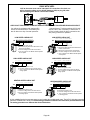
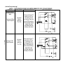
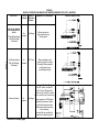
DELAY
The DELAY jumper is used to set the specific motor fan
mode of operation during cooling. Depending on the ap-
plication, one of four fan options may be chosen by moving
the jumper to the appropriate set of pins.
Options 1, 2, 3, or 4 will have an increased dehumidification
effect on the system. Option 1 will have the least effect and
option 4 will have the greatest effect.
#1 PIN JUMPERED
A − Motor runs at 100% until demand is satisfied.
B − Once demand is met, motor ramps down to off.
OFFOFF
A B
100% CFM
COOLING
DEMAND
#2 PIN JUMPERED
A − Motor runs at 82% for approximately 7−1/2 minutes.
B − If demand has not been satisfied after 7−1/2 minutes,
the motor runs at 100% until demand is satisfied.
C − Once demand is met, motor ramps down to off.
OFF
OFF
ABC
82%CFM 100% CFM
COOLING DEMAND
7 1/2 MIN
#3 PIN JUMPERED
A − Motor runs at 50% for 1/2 minute.
B − Motor then runs at 82% for approximately 7−1/2 min-
utes.
C − If demand has not been satisfied after 7−1/2 minutes,
motor runs at 100% until demand is satisfied.
D − Once demand is met, motor ramps down to off.
A
B
OFF
OFF
C D
1/2 MIN
50% CFM
7 1/2 MIN
82% CFM 100% CFM
COOLING DEMAND

Page 20
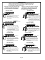
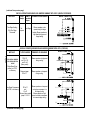
#4 PIN JUMPERED
A − Motor runs at 50% for 1/2 minute.
B − Motor then runs at 82% for approximately 7−1/2 min-
utes.
C − If demand has not been satisfied after 7−1/2 minutes,
motor runs at 100% until demand is satisfied.
D − Once demand is met, motor runs at 50% for 1/2 min-
ute.
E − Motor ramps down to off.
A
B
OFF
OFF
C D
E
1/2 MIN
50% CFM
COOLING DEMAND
7 1/2 MIN
82% CFM
100%
CFM
1/2 MIN
50% CFM
COOL
The cool jumper is used to set the blower speed to obtain
the required CFM as outlined in the blower performance
tables.
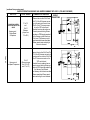
VSP Operation
Table 8 outlines the operation of the variable speed motor
in relation to specific modes of operation. See table 9 for
GHR32V with CCB1 and a two speed outdoor unit. Some
information has been repeated from the previous section to
provide an example. Refer to each diagnostic LED or jump-
er settings section for more information.
TABLE 8
GHR32V−4 Units with VSP3−1
Heating Mode Cooling Mode
Units With
Single−Stage Heating
Units With
Two−Stage Heating
Units With
Single−speed Compressor
Units With
Two−speed Compressor
Non−Zoned Applications
Using a single−stage thermostat
with "one−stage" heating, the HEAT
LED−DS2 is lit when the thermostat
calls for heat. The ON/OFF LED−
DS3 is lit after 110 seconds (65 sec-
onds prepurge and 45 seconds fan
"ON" time) from the time a call for
heat is made. This indicates the
blower is operating in high speed
heat.
Using a single−stage thermostat
with "W2 TIMED" and W1 calling,
the ON/OFF LED−DS3 is lit to indi-
cate the blower is operating on low
speed heat.
When HEAT LED−DS2 is lit, the
blower is operating in high speed
heat and second−stage (W2) is call-
ing.
Non−Zoned Applications
Using a two−stage thermostat with
first−stage (W1) calling, the ON/
OFF LED−DS3 is lit to indicate the
blower is operating in low speed
heat.
When the ON/OFF LED−DS3 and
HEAT LED−DS2 are lit, the blower
is operating in high speed heat and
second−stage (W2) is calling.
HEAT LED−DS2 is lit with a call for
heat from the thermostat. ON/OFF
LED−DS3 is after 110 seconds from
the time a call for heat is made.
Non−Zoned Applications
Y1−DS and Y1−Y2 must be jump-
ered together. With a call for cool-
ing, G, Y1, Y2 and DS on the unit
control board are energized from
the thermostat. HI/LOW LED−DS1
and ON/OFF LED−DS3 are lit to in-
dicate a call for cooling.
Note − Y1 to DS and Y1 to Y2 are
factory jumpered for single−stage
cooling, non−zoned applications.
Non−Zoned Applications
Y1−DS must be jumpered together.
With a call for single−stage cooling,
G, Y1, and DS on the unit control
board are energized from the Ther-
mostat. With a call for second−stage
cooling, G, Y1, Y2, and DS on the
unit control board are energized
from the thermostat. In both cases,
HI/LOW LED−DS1 and ON/OFF
LED−DS3 are lit to indicate a call for
cooling.
Note − Jumper Y1−Y2 must be re-
moved for units with two−speed
compressor.
Harmony Zoned Applications
The blower speed is controlled by
the PWM (pulse width modulation)
signal sent from the control center
of the zoning system to the terminal
strip’s DS terminal. HI/LOW LED−
DS1 and ON/OFF LED−DS3 are lit
to indicate the blower is operating.
Note − In Harmony II zoning ap-
plications, HTG BLOWER jumper
must be in position #2.
Harmony Zoned Application
The blower speed is controlled by
the PWM (pulse width modulation)
signal sent from the control center
of the zoning system to the terminal
strip’s DS terminal. HI/LOW LED−
DS1 and ON/OFF LED−DS3 are lit
to indicate the blower is operating.
Note − In Harmony II zoning applica-
tions, HTG BLOWER jumper must
be in position #2.
Harmony Zoned Application
The blower speed is controlled by
the PWM (pulse width modulation)
signal sent from the control center
of the zoning system to the termi-
nal strip’s DS terminal. HI/LOW
LED−DS1 and ON/OFF LED−DS3
are lit to indicate the blower is oper-
ating.
Harmony Zoned Application
The blower speed is controlled by
the PWM (pulse width modulation)
signal sent from the control center
of the zoning system to the terminal
strip’s DS terminal. HI/LOW LED−
DS1 and ON/OFF LED−DS3 are lit
to indicate the blower is operating.
NOTE − For zone applications with Harmony, remove the wire from pin #2 and pin #13 of the J49 terminal at the motor and the wire
from pin #3 of the J73 terminal on the VSP control board, insulate the ends and secure to prevent shorting.
Page is loading ...
Page is loading ...
Page is loading ...
Page is loading ...
Page is loading ...
Page is loading ...
Page is loading ...
Page is loading ...
Page is loading ...
Page is loading ...
Page is loading ...
Page is loading ...
Page is loading ...
Page is loading ...
Page is loading ...
Page is loading ...
Page is loading ...
Page is loading ...
Page is loading ...
Page is loading ...
Page is loading ...
Page is loading ...
Page is loading ...
Page is loading ...
Page is loading ...
Page is loading ...
Page is loading ...
Page is loading ...
Page is loading ...
Page is loading ...
Page is loading ...
Page is loading ...
Page is loading ...
Page is loading ...
Page is loading ...
Page is loading ...
Page is loading ...
Page is loading ...
Page is loading ...
Page is loading ...
Page is loading ...
Page is loading ...
Page is loading ...
Page is loading ...
Page is loading ...
Page is loading ...
Page is loading ...
Page is loading ...
Page is loading ...
Page is loading ...
Page is loading ...
Page is loading ...
Page is loading ...
Page is loading ...
Page is loading ...
Page is loading ...
Page is loading ...
Page is loading ...
Page is loading ...
Page is loading ...
Page is loading ...
Page is loading ...
Page is loading ...
Page is loading ...
Page is loading ...
Page is loading ...
Page is loading ...
Page is loading ...
Page is loading ...
Page is loading ...
Page is loading ...
Page is loading ...
Page is loading ...
Page is loading ...
Page is loading ...
Page is loading ...
Page is loading ...
Page is loading ...
Page is loading ...
-
 1
1
-
 2
2
-
 3
3
-
 4
4
-
 5
5
-
 6
6
-
 7
7
-
 8
8
-
 9
9
-
 10
10
-
 11
11
-
 12
12
-
 13
13
-
 14
14
-
 15
15
-
 16
16
-
 17
17
-
 18
18
-
 19
19
-
 20
20
-
 21
21
-
 22
22
-
 23
23
-
 24
24
-
 25
25
-
 26
26
-
 27
27
-
 28
28
-
 29
29
-
 30
30
-
 31
31
-
 32
32
-
 33
33
-
 34
34
-
 35
35
-
 36
36
-
 37
37
-
 38
38
-
 39
39
-
 40
40
-
 41
41
-
 42
42
-
 43
43
-
 44
44
-
 45
45
-
 46
46
-
 47
47
-
 48
48
-
 49
49
-
 50
50
-
 51
51
-
 52
52
-
 53
53
-
 54
54
-
 55
55
-
 56
56
-
 57
57
-
 58
58
-
 59
59
-
 60
60
-
 61
61
-
 62
62
-
 63
63
-
 64
64
-
 65
65
-
 66
66
-
 67
67
-
 68
68
-
 69
69
-
 70
70
-
 71
71
-
 72
72
-
 73
73
-
 74
74
-
 75
75
-
 76
76
-
 77
77
-
 78
78
-
 79
79
-
 80
80
-
 81
81
-
 82
82
-
 83
83
-
 84
84
-
 85
85
-
 86
86
-
 87
87
-
 88
88
-
 89
89
-
 90
90
-
 91
91
-
 92
92
-
 93
93
-
 94
94
-
 95
95
-
 96
96
-
 97
97
-
 98
98
-
 99
99


Lennox GHR32V Unit Information
- Category
- Water heaters & boilers
- Type
- Unit Information
Ask a question and I''ll find the answer in the document
Finding information in a document is now easier with AI
Related papers
-
Lennox G61MPV Series User manual
-
Lennox Elite G61MPV36C-090 User manual
-
-
Lennox G61MP?48C?090 User manual
-
-
-
-
-
-
Other documents
-
ICM Controls ICM2915 Application/Install Guide
-
-
-
-
Allied 95G1 Installation guide
-
ROYALTON 95G1UH045BP12 Installation guide
-
Trane AUH2C100A9V5VA Service Facts
-
COMFORT-AIRE GUH92A110C4M-CY User manual
-
American Standard AUY120R9V5W Service Facts
-