Page is loading ...

Crestron Green Light
®
Commercial Lighting Design Guide

© 2009
Crestron Electronics Inc.
15 Volvo Drive
Rockleigh, NJ 07647
800.237.2041
www.crestron.com
For Residential Lighting Solutions, refer to Doc. 5999
All brand names, product names, and trademarks are the sole property of their respective owners.

Crestron Commercial Lighting Design Guide
Contents
INTRODUCTION .................................................................. 1
C
RESTRON CONTROL TECHNOLOGY ..................................... 2
T
HE SINGLE SOLUTION CONTROL SYSTEM ........................... 2
S
YSTEM DESIGN ................................................................ 3
L
IGHTING SYSTEM DESIGN TYPES ....................................... 4
S
PECIFYING A LIGHTING SYSTEM ......................................... 8
R
EQUIRED LOAD SCHEDULE ITEMS .................................. 8
E
XAMPLE LOAD SCHEDULE WITH PANEL TERMINATIONS ....... 9
C
OMMERCIAL LIGHTING WIRING PLAN ............................ 10
E
QUIPMENT LIST SPECIFICATION ................................... 10
O
RDERING A CRESTRON COMMERCIAL LIGHTING SYSTEM ... 10
G
REEN LIGHT POWER SWITCHING ....................................... 11
SYSTEM
FEATURES ................................................... 11
GLPS-HSW ............................................................... 14
GLPS-SW .................................................................. 17
GLPS-HSW-FT .......................................................... 20
GLPS-SW-FT ............................................................. 22
GLPS-HDSW-FT ........................................................ 24
IPAC-GL1 .................................................................. 26
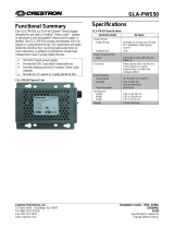
GLA-PWS50 .............................................................. 28
D
IMENSIONS ................................................................ 30
G
REEN LIGHT OPTIONS...................................................... 36
CAEN-
SERIES ENCLOSURES .......................................... 36
CAEN
INSTALLATION ................................................. 38
CAEN
ENCLOSURE FRAMING ....................................... 38
CAEN
WIRING ......................................................... 39
U
NIVERSAL MOUNTING PLATES .................................... 40
C
OVER EXTENSION KITS ............................................. 41
CLX
LIGHTING CONTROL MODULES .............................. 42
T
ERMINAL BLOCKS AND MODULES ................................ 44
C
RESNET® TERMINAL BLOCK FOR CAEN AUTOMATION
ENCLOSURES ........................................................... 46
C
RESTRON DIN RAIL PRODUCTS ........................................ 48
DIN-AP2 ............................................................... 50
DIN-1DIMU4 ......................................................... 51
DIN-8SW8 ............................................................ 52
DIN-4DIMFLV4...................................................... 52
DIN-2MC2 ............................................................ 52
DIN-AO8 ............................................................... 53
DIN-IO8 ................................................................ 53
DIN-BLOCK ........................................................... 54
DIN-PWS50 .......................................................... 54
DIN-HUB ............................................................... 55
I
NTERFACE EQUIPMENT ..................................................... 56
W
ALL MOUNT TOUCHPANELS .......................................... 57
T
ILT TOUCHPANELS ....................................................... 59
TPMC
SERIES ISYS I/O WIFI TOUCHPANELS ....................... 60
W
IRELESS TOUCHPANELS AND HANDHELDS ........................ 61
K
EYPADS ........................................................................ 62
C2N-DB
SERIES DECORATOR KEYPADS ............................ 62
CNX
DESIGNER SERIES KEYPADS ..................................... 63
C
AMEO™ ................................................................... 64
ILUX INTEGRATED LIGHTING CONTROL SYSTEM ..................... 66
ILUX FEATURES ........................................................ 67
W
IRELESS ILUX REMOTE ............................................ 67
M
ULTI-UNIT EXPANSION ............................................. 68
C
ONTROL SYSTEM INTEGRATION .................................. 69
ILUX EXPANSION MODULES ......................................... 70
W
ALL BOX DIMMERS AND SWITCHES .................................. 72
C
RESNET WALL BOX DIMMERS .................................... 73
C
RESNET WALL BOX SWITCHES ................................... 74
INFINET™ WIRELESS TECHNOLOGY ................................... 75
C
ONTROL PROCESSORS ..................................................... 78
PAC2
LIGHTING CONTROL PROCESSOR ............................. 78
PAC2M
PROFESSIONAL AUTOMATION MINI CONTROL SYSTEM 80
O
CCUPANCY AND PHOTOCELL SENSORS ............................... 83
GLS-ODT
& GLS-OIR ................................................. 83
GLS-LOL
& GLS-LCL ................................................. 83
I
NTEGRATED SHADE AND DRAPE CONTROLLERS .................... 84
C2N-SDC .............................................................. 84
C2N-SDC-DC ........................................................ 84
C2N-SSC-2 .......................................................... 84
I
NTEGRATED PARTNER MODULES ........................................ 85
A
PPENDIX A: ................................................................... 86
R
OOMVIEW
®
REMOTE ASSET MANAGEMENT ......................... 86
R
OOMVIEW SERVER EDITION ........................................... 86
R
OOMVIEW EXPRESS ..................................................... 89
A
PPENDIX B .................................................................... 90
G
REEN LIGHT DESIGNER SOFTWARE™: ............................. 90
A
PPENDIX C: TOUCHPANEL COMPARISON CHARTS ................. 92
T
ILT TOUCHPANELS ....................................................... 92
W
ALL MOUNT TOUCHPANELS .......................................... 93
W
IRELESS TOUCHPANELS & HANDHELD REMOTES ................ 94
A
PPENDIX D: GENERAL LIGHTING DESIGN CONSIDERATIONS .... 95


Crestron Commercial Lighting Design Guide Introduction
Doc. 4775A 1
Introduction
Crestron is the world's leading manufacturer of advanced
control technologies. Our developments in combining
touchpanel technology with lighting control applications
were the very first of their kind.
Only Crestron brings the most comprehensive line of user-
interfaces to lighting and dimming control, plus the ability
to remotely monitor, manage and control over standard IP
networks.
Cresnet
®
low-voltage wiring and/or RF control can be used
throughout a wide range of system design possibilities,
including traditional wiring with local intelligence or
distributed, high-voltage wiring with centralized and/or
distributed intelligence systems.
The wide range of Crestron multi-function user interfaces
replaces large banks of traditional switches, dimmers, and
timers. In addition to lighting, these user interfaces can
also control security, HVAC, and audio/video systems. Only
Crestron provides a single control wiring bus to all of its
components, simplifying installation and connection.
Each unique lighting control system reflects the needs and
desires of the inhabitants. Designing and constructing a
lighting and automation system to fill the requirements of
your client is a challenging task, and Crestron offers the
equipment and flexibility of design required for every
one-of-a-kind solution.
Crestron interfaces provide manual and automatic controls;
turning on exterior lights based on an astronomical clock,
providing a single button press to turn all lights on,
illuminating safe exits in case of emergency, and many
other lighting possibilities.
Crestron products allow the designer to continually expand
and change any lighting system. Crestron infiNET
TM
wireless devices provide a simple retrofit solution to
expand a existing systems. Every Crestron lighting system
is completely modular and scalable, allowing virtually
unlimited configuration and expansion flexibility.
Crestron eliminates the need to walk from room to room
to adjust drapes, lights, temperature, and audio/video
components- total control is always at your fingertips
Crestron Green Light™
Crestron Green Light is a complete line of lighting, HVAC,
and shade/drape control for both commercial and
residential applications, designed to maximize energy
conservation and cost savings.
Crestron Green Light solutions underscore the company's
ongoing commitment to environmental safety and energy
conservation. Only Crestron offers a fully integrated global
systems approach with the unique ability to monitor and
manage all environmental and AV systems on a single
platform that maximizes efficiencies and cost savings.
Crestron Green Light technology delivers total
environmental control throughout a home or commercial
facility to conserve energy and lower costs without
sacrificing comfort and convenience. Crestron systems
provide users the flexibility of both precise manual control
of all systems and devices, and customized levels of
automation to achieve advanced features such as daylight
harvesting and load shedding. Only Crestron can schedule,
monitor and manage all technology centrally and globally
from touchpanels and PCs.
Crestron Green Light products meet ASHRAE standards and
are fully CEC Title 24 compliant. Crestron is a member of
the U.S. Green Building Council (USGBC), the organization
responsible for creating the LEED Green Building Rating
System™. Crestron Green Light solutions take a whole-
building approach to sustainability, and facilitate the
efficient operation of high performance green buildings.
Additionally, all Crestron Green Light products conform to
the European Union (EU) Directive 202/95/EC Restriction of
Hazardous Substances (RoHS).
Crestron Roomview™ software (appendix A) monitors
controls, schedules and tracks assets. Facility mangers can
perform remote system diagnostics and automate tasks
through event scheduling
Crestron Green Light™ Designer software (appendix B)
allows you to design and document a complete, energy-
efficient commercial lighting solution that combines
facility-wide lighting, shade/drape control with audio/video
integration and network management—all without
requiring extensive knowledge of Crestron products,
or any other Crestron software.
.

Introduction Crestron Commercial Lighting Design Guide
Doc. 4775A 2
Crestron Control
Technology
View precise lighting levels, temperature and shade
positions in any room throughout the installation, graphically
and quantitatively, from any touchpanel or PC.
Monitor and track current and historical device usage
and intelligently manage resources.
Ethernet connectivity enables LAN or web-based system
control and management, and sends email advisories about
pre-determined events such as devices going off-line
or automatic load shedding.
Crestron control processors provide the total integration of
Crestron devices, non-Crestron devices, and subsystems
in any environment, for any purpose, anywhere. Crestron
control processors can connect to any digital, serial, or
analog system, and control by RF, IR, or hardwiring,
making them the most flexible, powerful control systems
ever devised.
Underlying the hardware are powerful, graphical
programming tools, specifically designed to establish total
control over any technology and make the user experience
uncomplicated, intuitive, and easy to use.
Crestron also provides true feedback for essential control
monitoring, function response to controls, and user inputs.
Crestron offers design solutions for every situation.
Selecting the proper equipment often depends on the kind
of installation. New construction, major renovation, or minor
renovation each present different design challenges.
Single Solution Control
System- Crestron Exclusive
Crestron connects people with technology. As products and
systems become more complex, our solutions streamline and
simplify technology so people can enjoy its benefits.
We understand that our touchpanels, keypads, and handhelds
are how people interact with and experience the systems in
their homes, offices, schools and churches. We allow
individuals to create a comfortable environment, set a mood,
and enjoy technology.
With our wide range of interface products, slim profile wall
mount keypads and decorative faceplates, our products
enhance a décor, complement a lifestyle, or personalize a
room. Crestron offers the most brilliant graphics and intuitive,
customized interfaces. We integrate more of the technology
that people want and use everyday into our touchpanels; and
provide ergonomically designed and easy-to-use wireless
controllers, and flush-mount touchpanels of every size.
Tying all this technology together seamlessly is our exclusive
Cresnet
®
cable, connecting the user to a powerful and flexible
control system.

Crestron Commercial Lighting Design Guide System Design
Doc. 4775A 3
System Design
The applied lighting control strategy determines the basic methods used to
control the environment. When formulating an overall strategy, there are some
basic considerations:.
New construction and major renovations provide the opportunity to
easily run control cables from user interfaces to the control processor
when the walls are open.
Existing construction or minor renovations often make the task of
running cables more difficult, time consuming, expensive, or even
impossible (in historic landmarks, etc.). In this case, you may choose
to install a partialyl or completely wireless system
Light level control is achieved through dimming controls and daylight
management, where applicable, to adjust the lighting to the
appropriate level for different occupant activities
Occupancy sensing is used to switch the lighting on and off,
independent of time intervals or scheduled periods. This allows the
space to be responsive to individual use, and conserves energy
Scheduled lighting is determined by time of day, day of week,
vacation, outdoor lighting, and safety lighting requirements. An
astronomical clock (programmed with sunrise and sunset information)
is often used to provide natural lighting transitions
HVAC control should be part of the overall control strategy, permitting
additional economic and convenience benefits

Crestron Commercial Lighting Design Guide System Design
Doc. 4775A 4
Lighting System Design Types
There are many ways in which a Crestron lighting control
system can be organized. Construction type, client
requirements, architectural restrictions, and many other
factors determine the best solution. In general, retaining
Crestron control design flexibility produces the most
reliable results.
Wireless Systems
The groundbreaking Crestron infiNET wireless technology
provides reliable 2-way communications throughout a
home or commercial structure without the need for
physical control wiring. Crestron infiNET products offer a
unique solution for retrofit projects. By replacing existing
controls with infiNET switches and dimmers, provisions
for automatic shutoff and overall control can be
implemented with minimal changes to the existing wiring.
Employing a 2.4 GHz mesh network topology, every
infiNET device functions as an RF repeater, increasing
effective range and reinforcing the complete network by
providing multiple redundant signal paths within the mesh
network. Adding more infiNET devices or repeaters to the
network effectively increases the range, strength, and
reliability of the network.
Advantages of RF wireless control start with reduced
capital and operating expenses. Wireless control can save
as much as 30 to 40 percent on installation and material
costs compared to a wired control system, making this
option attractive for retrofit as well as new construction.
Installation costs are reduced because RF devices can
be replaced one to one without involving control wiring.
Crestron infiNET Wireless System

Crestron Commercial Lighting Design Guide System Design
Doc 4775A 5
Centralized Wired Systems
A centralized system is one in which all the high-voltage
circuits are terminated within a Crestron automation
enclosure and operate under a central control system. In a
centralized design, the high voltage lighting, fans, motors
and switch circuits are individually wired directly to the
control modules in the Crestron automation enclosure.
The modules are controlled by low voltage or RF user
interfaces in the living area. This greatly simplifies the
high voltage wiring while creating a flexible and efficient
design using keypad and touchpanel interfaces.
A central processor, connected via a local area network to
the lighting modules and the user interfaces, is dedicated
to lighting, fans, motors, HVAC, and security. Processors
that are dedicated to other control systems can
communicate via Ethernet, RS-232 or RS-422 to the
central controller. This eliminates the need for additional
control that separate safety and environmental systems
and is a flexible, fully integrated design solution.
A Centralized Wiring System

System Design Crestron Commercial l Lighting Design Guide
Doc. Doc 4775A 6
Decentralized Wired Systems
A decentralized system is the traditional wiring system
of individual lighting circuits with local control. In the
traditional distributed design wiring method, Crestron wall
box dimmers can be retrofitted into a project after routine
high voltage wiring is completed.
In addition to the traditional high voltage wiring, a low
voltage communication wire can be run from the dimmer
to the nearest Cresnet® connection (or an RF wireless
control can be used). This design offers the end user the
familiarity of a traditional control coupled with the power
and flexibility of automation. In a distributed design, the
user has the ability to operate the lighting in the event of
a temporary control system interruption.
A Decentralized Wiring System

Crestron Commercial Lighting Design Guide System Design
Doc 4775A 7
Hybrid Systems
The most efficient and attractive lighting system designs
are a hybrid of centralized processing and distributed
dimmers. This provides the reliability of local control along
with sophisticated centralized control, and limits the
amount of wall clutter
A complete Crestron design is a blend of wireless and
wired, distributed and centralized design in which central
control intelligence and distributed local dimmers form a
reliable whole house lighting control solution.
Large rooms, stairways, and frequently used rooms are
often remotely controlled using the astronomical time
clock or whole house presets. This level of control
requires connection to a central dimming controller. Each
room is equipped with a low voltage or wireless keypad
for lighting preset selection and/or audio/video integration.
All of the dimmers in the system (grouped into the central
controller for wiring convenience) communicate with each
other through the Crestron control system, providing a
complete, integrated solution
A Hybrid Wiring System

Crestron Commercial Lighting Design Guide Specifying a Lighting System
Doc. 4775A 8
Specifying a Lighting
System
The Load Schedule
A lighting system design begins with a collection of
complete information. This includes a detailed floor plan
identifying all of the required elements. The first element
of design, the load schedule, is developed from the floor
plan. The load schedule lists the information on each
electrical load connected to every circuit in an electrical
panel. This primary source of information determines all
of the overall requirements:
Lighting types, required voltage and current,
dimmed or switched, fluorescent ballast types,
circuit number, normal or emergency, and
locations
The location and types of user interfaces used
(i.e., dimmers, switches, keypads, iLux™,
infiNET™, and touchpanels)
The control processor details (larger systems
should use a dedicated lighting control processor)
The window treatment details, which include
shade/blind motors and relay control (consult
the window treatment manufacturer for control
details).
Required Load Schedule Items
1. Control zone: Controlled circuits that do not need
to be physically wired together, but always operate
in tandem. For example, perimeter lights, sconce
lights and overhead lights all operating together
2. Location of controlled lighting zone, relevant to
building site/drawings, floor designation, and
room name
3. Fixture and/or lamp type of controlled lighting
zone, including any information describing custom
fixtures, undetermined fixtures, dimmable
transformers or fluorescent ballasts, and circuit
breaker numbers. This information can also contain
the number assigned to the controlled circuit
4. Load type of the controlled lighting zone: load types
include incandescent, magnetic low voltage,
electronic low voltage, neon/cold cathode, HID,
dimmable/non-dimmable fluorescent ballast, ceiling
fans, and switched 3-wire motor circuits. This
information is especially important for selecting the
correct Crestron module power rating and type
5. Dimming requirement for the controlled lighting
zone (i.e. whether the lighting level of the
loads/fixtures needs to be ramped up/down or
simply switched on/off). Indicate: “Yes” for
Dimming, and “No” for Non-Dim
6. Emergency designation for the controlled lighting
zone (yes/no; i.e. when a load needs to be assigned
to a separate emergency power feed). These items
are assigned to their own separate dimmer, so they
can be fed with emergency power
7. Voltage rating for the controlled lighting zone tells
the designer the voltage of the electrical feeds
required for that zone, and hence the required
rating for the associated Crestron module.
8. Fixture wattage (watts or power rating per fixture)
with regard to the controlled lighting zone: this is
used to determine the number of fixtures that can
be powered per each Crestron Dimmer Module
channel, in order not to overload the dimmer
beyond its power rating
9. Quantity of fixtures for the controlled lighting zone:
this is useful, along with item #6, in calculating the
total power rating (watts) for that particular
controlled circuit (item #9)
10. Total wattage, or power rating, of the controlled
lighting zone: This is required in order to determine
the total number of Crestron Lighting Module
channels required for that particular zone,
especially if the load of the total number of fixtures
exceeds the rating of a single module channel
A riser diagram is requied for commercial lighting
projects. The simgle lin or sier diagram indicates
system components connected to individual circuits
in the system. Components connected to a
common circuit are shown as being connected to a
single line, regardless of the number of conductors
actually used. The number of conductors in each
wiring segment is usually indicated by right angle
marks across the single line at that point or by other
appropriate means
NOTE: National and local electrical codes and the
functionality of each user interface must be taken
into consideration. Always install electrical devices
according to the national Electrical Code (NEC), local
codes, and with safety in mind.

Crestron Commercial Lighting Design Guide Specifying a Lighting System
Doc 4775A 9
Example Load Schedule with Panel Terminations
Area Room
Controlled Ckt
Name
Controlled
Ckt No. Fixture Load Type Dim Emergency
Fixture
Watts
Fixture
Qty
Total
Watts Enclosure Slot Module Output
Main Floor Bathroom 1 Downlights 009 Downlights Incandescent yes no 100 1 100 Enclosure 1 2 CLX-1DIM8 1
Main Floor Bathroom 1 Downlights 2 008 Downlights Incandescent yes no 100 2 200 Enclosure 1 2 CLX-1DIM8 2
Main Floor Bathroom 1 Downlights 3 006 Downlights Incandescent yes no 100 2 200 Enclosure 1 2 CLX-1DIM8 3
Main Floor Bathroom 1 Drapes 019 Drapes 3-Wire Motor no no 200 1 200 Enclosure 1 4 CLX-1MC4 1
Main Floor Bathroom 1 Exhaust Fan 007 Exhaust Fan Switched no no 200 1 200 N / A N / A Interface 2 1
Main Floor Bathroom 2 Downlights 011 Downlights Incandescent yes no 100 1 100 Enclosure 1 2 CLX-1DIM8 4
Main Floor Bathroom 2 Downlights 2 010 Downlights Incandescent yes no 100 3 300 Enclosure 1 2 CLX-1DIM8 5
Main Floor Bathroom 2 Drapes 021 Drapes 3-Wire Motor no no 200 1 200 Enclosure 1 4 CLX-1MC4 2
Main Floor Bathroom 2 Exhaust Fan 012 Exhaust Fan Switched no no 200 1 200 N / A N / A Interface 4 1
Main Floor Bedroom Ceiling Fan 022 Ceiling Fan Ceiling Fan no no 100 1 100 Enclosure 1 6 CLX-1FAN4 1
Main Floor Bedroom Downlights 005 Downlights Incandescent yes no 250 2 500 Enclosure 1 2 CLX-1DIM8 7
Main Floor Bedroom Downlights 2 004 Downlights Incandescent yes no 100 4 400 Enclosure 1 3 CLX-1DIM4 1
Main Floor Bedroom Downlights 3 003 Downlights Incandescent yes no 100 1 100 N / A N / A Interface 6 1
Main Floor Bedroom Downlights 4 002 Downlights Incandescent yes no 100 1 100 N / A N / A Interface 5 1
Main Floor Bedroom Downlights 5 001 Downlights Incandescent yes no 100 2 200 Enclosure 1 3 CLX-1DIM4 2
Main Floor Bedroom Drapes 018 Drapes 3-Wire Motor no no 200 1 200 Enclosure 1 4 CLX-1MC4 3
Main Floor Bedroom Drapes 2 017 Drapes 3-Wire Motor no no 200 1 200 Enclosure 1 4 CLX-1MC4 4
Main Floor Bedroom Drapes 3 016 Drapes 3-Wire Motor no no 200 1 200 Enclosure 1 5 CLX-1MC4 1
Main Floor Foyer Downlights 013 Downlights Incandescent yes no 100 4 400 Enclosure 1 2 CLX-1DIM8 6
Main Floor Sauna Drapes 020 Drapes 3-Wire Motor no no 200 1 200 Enclosure 1 5 CLX-1MC4 2
*Calculation of load wattage includes transformer loss.
The complete diagram is available on line at:
http://www.crestron.com/dealer-tech_resources/application_diagrams.asp
.

Specifying a Lighting System Crestron Commercial Lighting Design Guide
Doc. Doc 4775A 10
Commercial Lighting Wiring Plan
The wiring plan includes all enclosures and the
interconnecting wiring. The designer determines the
location of the enclosure(s), the route of keypad and
touchpanel connections to the enclosure(s), the route
of the interconnecting cable from the processor to the
other enclosure(s), and the high voltage load routes
to the enclosure or dimmer.
Ensure there are enough connectors and power (PAC2 offers
50W) in the main enclosure for all user interfaces. Each
enclosure filled with dimmers is connected to the main
enclosure and processor using low voltage wire. Dimmer
enclosures are distributed as needed.
Equipment List Specification
The equipment list is based on the requirements collected for
the lighting system in the load schedule. This is a sequential
process. The information gathered in previous steps is
required to complete the next. Once all the steps are done,
a complete Bill of Material for the system is created.
Module selection – based on the number and type
of loads
Automation enclosure selection – based on the
number of modules and the available space in the
enclosure
User interface selection – based on the user control
requirements
Wiring plan – based on the previous steps and the
layout of the environment
Control processor – based on the size of the system
(large systems should have a dedicated processor)
Network block selection – based on the layout and
distribution of the loads and user interfaces
Accessories selection – based on the required
accessories (telephone and alarm systems, HVAC
control, intercom systems, occupancy sensors, etc.)
Ordering a Crestron Commercial
Lighting System
These are the steps for ordering a Crestron commercial
lighting control system, regardless of the size.
Each system and module contains the appropriate installation
literature and operation guide.
Steps to order a lighting system:
STEP 1: Survey all controlled lights and loads. In hybrid
systems determine which loads are under local control and
which are to be wired to centralized modules
STEP 2: Determine the number and types of control modules
and terminal blocks needed to control lights and loads based
on the load schedule and wiring plan
STEP 3: Determine the number and type of automation
enclosures required
STEP 4: Determine the number of control processors and
related accessories required
STEP 5: Determine the number and types of keypads,
wall panels, iLux™ devices, infiNET™ wireless devices,
shade/drape controllers, and touchpanels
STEP 6: Determine the wiring accessories, cabling and
power supplies required
STEP 7: Place an order for identified Crestron items
Nearly all required documentation, such as load schedules
and wiring, equipment lists, engraving files and more can
be generated by using the Crestron D3 Pro Lighting and
Automation System Software.
Crestron ships all items to the job site for assembly and
wiring.
Note: Crestron Green Light Panels are shipped assembled
and are to be commissioned by Crestron.

Crestron Commercial Lighting Design Guide Green Light Power Switching
Doc. 4775A 11
Green Light Power
Switching
C
restron Green Light Power Switching is a family of switching
systems designed for control of lighting in office buildings,
warehouses, parking garages, sports facilities, public spaces,
and anywhere centralized switching is required. With a range
of panel sizes and configurations available, every system is
fully scalable to fit each installation perfectly. An extensive
selection of Crestron keypads, touchpanels, occupancy
sensors, photocells, shade controllers, and numerous other
peripheral options afford astounding design flexibility with
unparalleled capability for integration
Green Light Power Switching is simple to install and easy to
program. Native features include an astronomical time clock
to allow scheduling of events to occur around the rise and fall
of the sun. Other powerful, energy saving capabilities include
occupancy sensing to turn off lights when they are not
needed, daylight harvesting to harness natural light from
windows and skylights, and emergency override to assure
safe and reliable lighting of critical areas in the event of a
power outage or emergency condition.
Scalable and field-serviceable modular design
Switching control for all types of lighting loads and motors
up to 2 HP
All outputs rated at 16A @ 120V and 277V (347V also available)
Local front panel relay controls
3 high-performance relay types available
UL 508 Section 61C rated for electronic ballast
Available 0-10V fluorescent dimming control
Positive air gap at each output
Feed-through, main lug only, main circuit breaker options
CEC Title 24 listed
Astronomical time clock
Occupancy sensing and daylight harvesting
Emergency override capability
Easy programming via the IPAC-GL1 lighting processor
Extensively programmable via PC software
Wide selection of interface and computer control options
Optional shade and drape controllers
Crestron RoomView® remote management
Integration into building management systems
System design by Crestron
Factory assembled and tested
SYSTEM FEATURES
High-Performance Power Switching
—
Crestron GLEP Series
power switching panels feature field-replaceable switching
modules with a choice of relay technologies to address a
wider range of applications and budgets.
Our top of the line GLPS-HSW panels employ robust 50 Amp
mechanically-latching relays in combination with advanced
zero-cross arcless technology to achieve a relay lifetime of
one million cycles. For a higher density switching solution,
our GLPS-SW panels utilize the same rugged 50 amp relays
while putting more controlled circuits in less space. Either
panel supports both 120 and 277 voltages, and includes
main lugs and integrated branch circuit breakers.
For installations using a separate circuit breaker panel,
Crestron offers the Green Light Express series of
“
feed-
through
”
panels. Like their "main lug" panel counterparts
above, the GLPS-HSW-FT and GLPS-SW-FT panels feature
zero-cross arcless switching and standard high-inrush
switching respectively. Green Light Express also offers one
more relay option in the GLPS-HDSW-FT, utilizing heavy duty
GLPS-HSW Panel

Green Light Power Switching Crestron Commercial Lighting Design Guide
Doc.4775A 12
modular relays for an extra level of flexibility switching 120,
277, and 347 volt loads.
In addition to switching, some Green Light Power Switching
panels also allow the option to add dimming control for 0-10V
dimmable fluorescent ballasts
.
The IPAC-GL1 Control Processor—Crestron has been
manufacturing and innovating microprocessor-based control
systems for lighting and automation longer than anybody,
and all of that know-how has gone directly into the IPAC-GL1.
Right from its front panel, an entire system of lighting loads,
keypads, touchpanels, sensors, and scheduled events
can be programmed without ever having to connect a
computer.
Featuring the same 2-Series control engine as other Crestron
processors, the IPAC-GL1 allows advanced programming to
support all kinds of control options and interfaces, custom
functionality and extensive integration with third-party
systems. Crestron processors also deliver the most
comprehensive capabilities available for remote control
and management over an IP network.
Local Controls—Crestron Green Light simplifies installation by
providing local controls right on the front of each switching
module. Even before the lighting processor gets installed,
these simple controls can be used to switch each load on
and off for testing and operation during construction.
Emergency Override—Remote emergency override capability
allows a power loss sensor (GLS-PLS-120/277) or any
external contact closure to override the lighting system
program and set each circuit to its override preset state. In
a power failure situation using a backup power source, this
allows designated emergency lighting circuits to be turned on
immediately. Override settings can be made easily using the
local controls on the front of each switching module.
Cresnet
®
—Each Green Light Power Switching panel
communicates with the IPAC-GL1, or other Crestron 2-Series
processor, via the Cresnet control network. This simple 4-
wire bus affords proven reliable digital control and flexible
system configuration, carrying data communications and 24
volt DC power to support a complete system of lighting
panels, keypads, touchpanels, sensors, and numerous other
Cresnet devices while connected to an IPAC-GL1 Integrated
Professional Automation Computer.

Crestron Commercial Lighting Design Guide Green Light Power Switching
Doc 4775A 13
Crestron Green Light Power Switching Panels are available in five basic configurations. Use to the following cross-reference table to
begin specifying the configuration that fits your application.
This table represents the full line of Crestron Green Light and Green Light Express Power Switching panels, as well as Green Light
and Green Light Express Architectural Dimming panels. All are shown side-by-side for easy comparison. The Power Switching panels
are each fully detailed under their respective specifications pages within this document. For details about Architectural Dimming
panels, please refer to the Crestron Green Light™ Architectural Dimming Specification Guide, Doc. 4785 (future).
GREEN LIGHT GREEN LIGHT EXPRESS
Power Switching Architectural Dimming Power Switching Architectural Dimming
GLPS-HSW
GLPS-SW
GLPD-DIM
GLPS-HSW-FT
GLPS-SW-FT
GLPS-HDSW-
FT
GLPD-DIM-FT
GLPD-DIMX-FT
Switching Relay Types
A
rcless High-inrush
Standard high-inrush
Modular high-inrush
2-pole available
Dimming Load Types
Incandescent, MLV
ELV
2-wire fluorescent
3-wire fluorescent
0-10V fluorescent
Ratings
Voltages
120/230/277 120/230/277 120/230/277 120/230/277 120/230/277
120/230/
277/347
120/230/277 120/230/277
Output capacity lighting
loads
16A 16A 16A
4
16A 16A 20A 16A
4
8A
Output capacity, motor
loads@ 120/230/277 volts
0.5/1/1 hp 1/2/2 hp 0.5/1/1 hp 0.5/1/1 hp 1/2/2 hp
0.5/1.5/1.5
hp
0.5/1/1 hp
Rated relay lifetime
5
1,000,000 10,000 1,000,000 1,000,000 10,000 30,000 1,000,000
Circuit Breakers
Integrated branch breakers
A
vailable main breake
r
Additional Features
Load state indicators
Local override
Emergency override
Mechanical override
Local control access door
option
Backup power supply
capable
Notes:
1.Please see Crestron Green Light™ Architectural Dimming Specification Guide, Doc. 4785 (future) for full description and specifications.
2. Supported via use of appropriate CLS-EXP expansion module.
3. 3-wire fluorescent loads require 2 control outputs per load.
4. Consult detailed specifications for ratings for ELV loads.
5. Relay lifetime based on number of cycles (on/off) with full electronic ballast load.

Green Light Power Switching Crestron Commercial Lighting Design Guide
Doc.4775A 14
GLPS-HSW Green Light Power Switching
Panels (MLO) Main Lug Only and (MCB) Main Circuit
Breaker Zero-Cross Arcless Relays
The GLPS-HSW Power Switching Panels come standard
with 20A branch circuit breakers, and accept 208Y/120 or
480Y/277 volt feeds terminating to main lugs provided. An
optional back-fed main circuit breaker may also be specified.
Four panel sizes are available, dubbed “Small,” “Medium,”
“Large,” and “Extra Large.” The panel size is ordinarily
determined according to the number of control circuits
specified, ranging from 8 to 42 circuits per panel. Each
control circuit is rated for 16A at 100-277V.
The GLPS-HSW panels utilize Crestron zero-cross arcless
relay technology, achieving a relay lifetime of one million
cycles. A high-current triac is employed to handle the
high-inrush current turn on, especially with certain load
types such as HID and electronic ballasts. Within
milliseconds, the continuous load is transferred to a
robust 50A mechanically-latching relay. All switching
occurs at the zero-cross point of the AC waveform under
microprocessor control. This is a complete solution
eliminating arcing at the physical relay contacts during
turn on and turn off, and supports switching of all types
of lighting loads up to 16A at 100V to 277V, as well as
motors up to 1 HP.
As an option, GLPS-HSW panels may be equipped with 0-10V
fluorescent dimming control substituted in place of some or
all switching circuits. Consult Crestron Sales Support
Services to specify this option.
The GLPS-HSW panels employ field-replaceable lighting
control modules, with 8 or 12 control circuits per module,
for excellent configurability and serviceability. Each module
includes local relay controls and load state indicators for each
circuit, plus additional controls and indicators for use during
system commissioning.
Individual hinged doors are provided on the front of each
GLPS-HSW panel for access to the circuit breaker panelboard
and the local controls on each module. As an option, the local
control access door may be omitted.
As part of a complete Green Light system, GLPS-HSW
panels connect to an IPAC-GL1 lighting control processor
(or other 2-Series control system) via the Cresnet
®
control network. An optional GLA-PWS50 (or equivalent)
power supply is also recommended for each panel to provide
backup power to the lighting modules.
Remote emergency override mode allows the lighting system
program to be overridden while each circuit is set to an
override preset state. The override preset for each circuit is
set using the local controls on the front of each lighting
module. Remote override mode is activated by an external
contact closure from a Crestron GLS-PLS-120/277 power
loss sensor or other device.
All low-voltage connections to a GLPS-HSW panel are made
via a connector block located near the bottom of the panel.
Connections are provided for Cresnet communications,
backup power supply, and emergency override.
Crestron Green Light Power Switching panels are configured
to order, factory assembled and tested prior to shipping. Each
panel is engineered to provide a clean and manageable
installation with provisions for wire termination and conduit
knockouts. On-site installation is fast and easy with all
termination points clearly labeled and accessible from
the front.
MODEL NUMBERS
Specifying and ordering a Crestron Green Light Power
Switching panel is facilitated using the following model
number system. Simply fill in the appropriate entry in each
position according to the steps that follow:
GLPS–HSW–MLO–30–120–10K –ND
GLPS-Relay Type-Feed Type-Number of Ckts-Voltage-AIC Rating-Door Option
The above example is for a “Main Lug Only” panel with 30
“HSW” zero-cross arcless relays, 120V / 10kAIC circuit
breakers, and no local control access door.
Relay Type: Enter “HSW” to specify zero-cross arcless
switching relays.
Notes: For other relay types, refer to the Selection Guide
0-10V fluorescent dimming is also available. Consult Crestron
Sales Support Services to specify this option.

Crestron Commercial Lighting Design Guide Green Light Power Switching
Doc 4775A 15
Feed Type: Choose one of the following to specify the type of
feed:
MLO Main lug only
MCB60 60A back-fed main circuit breaker
MCB80 80A back-fed main circuit breaker
MCB100 100A back-fed main circuit breaker
MCB125 125A back-fed main circuit breaker
(available for 277V only)
Note: Main feeds are 3-phase, 4-wire; rated 225A @ 120/208V
or250A @ 277/480V. Consult Crestron Sales Support Services for
400Afeed and other main circuit breaker options.
Number of Circuits: choose one of the following numeric
values from the appropriate column to specify the number
of controlled circuits in the panel:
Note: “Small,” “Medium,” “Large and “Extra Large” refer
to the default panel size per number of circuits. Consult
Crestron Sales Support Services for alternate configurations.
Voltage: To specify the circuit breaker voltage, enter “120”
for 120/208V or “277” for 277/480V.
AIC Rating: Choose one of the following values from the
appropriate column to specify the Ampere Interrupting
Capacity of the circuit breakers:
Note: Consult Crestron Sales Support MCB options.
Door Option—Enter “ND” to omit the local control access
door. (The circuit breaker door cannot be omitted).
GLPS-HSW-MLO GLPS-HSW-MCB
Small: 8, 12 8, 12
Medium: 16, 20, 24, 28, 30 16, 20, 24, 27, 30
Large: 32 32
Extra Large: 36, 40, 42 36, 39
120 Volt 277 Volt
10K 18K
22K 35K
65K 65K

Green Light Power Switching Crestron Commercial Lighting Design Guide
Doc.4775A 16
GLPS-HSW (Continued)
SPECIFICATIONS
Load Ratings
Switch Channels: 8 to 42 depending upon panel size and options,
each channel phase-independent
Maximum per Channel: 16 Amps @ 100 to 277 Volts AC, 50/60 Hz;
1/2 HP @ 120 Volts, 1 HP @ 277 Volts
Switched Load Types: Incandescent, Magnetic Low-Voltage,
Electronic Low-Voltage, Neon/Cold Cathode, Fluorescent Lamp
Ballast, High-Intensity Discharge, Motors
Dimmed Load Types (special order): 0-10 Volt 4-Wire Dimmable
Fluorescent Ballast
Rated Relay Lifetime: 1,000,000 cycles at full rated electronic ballast
load
Input Power
Line Power:120/208 VAC, 225 Amps maximum, 50/60 Hz
phase-to-neutral, or 277/480 VAC, 250 Amps maximum, 50/60 Hz
phase-to-neutralCresnet Power Usage (optional): 50 Watts (2.08
Amps @ 24 Volts DC) per panel, use Crestron GLA-PWS50 or
equivalent power supply
Circuit Breakers
Branch, 120V: 20A Square D
®
QOB Bolt-on type; 10k, 22k, or 65k
AIC rated as required
Branch, 277V: 20A Square D
®
EDB, EGB, EJB E-Frame type; 18k,
35k, or 65k AIC rated as required
Main, 120/208V (optional): 120/208V: 60A, 80A, or 100A Square D
®
QOB Bolt-on type; 10k AIC rated (consult Crestron for additional
options)
Main, 277/480V (optional): 60A, 80A, 100A, or 125A Square D
®
EDB, EGB, EJB E-Frame type; 18k, 35k, or 65k AIC rated
Lightning Protection
Can withstand 6 kV / 3 kA surge, as per IEC 61000-4-5 and
ANSI/IEEE C62.41-1991
Enclosure
NEMA Type 1, IP20 rated protection, for indoor use only
Back Box: 16 Gauge galvanized steel, surface wall mount
Front Cover: 16 Gauge steel, grey powder coat finish
Environmental
Temperature: 32° to 104°F (0° to 40°C)
Humidity: 10% to 90% RH (non-condensing)
Small: 37-1/2 x 20-1/4 x 6-5/8 in (95.25 x 51.4 x 16.8 cm) HWD
Medium: 70 x 20-1/4 x 6-5/8 in (177.8 x 51.4 x 16.8 cm) HWD
Large: 78-15/16 x 20-1/4 x 6-5/8 in (200.5 x 51.4 x 16.8 cm) HWD
Extra Large: 90 x 20-1/4 x 6-5/8 in (228.6 x 51.4 x 16.8 cm) HWD
Weight
Fully loaded with modules, 277V circuit breakers, and wiring:
Small: 70 lb (31.8 kg) maximum
Medium: 140 lb (63.5 kg) maximum
Large: 165 lb (74.9 kg) maximum
Extra Large: 181 lb (82.1 kg) maximum
Testing & Compliance
UL Listed, FCC Part 15
Feed Wiring – 120/208V
Neutral and Main Lugs:
10-2/0 AWG (CU)
6-2/0 AWG (AL)
6-300 kcmil (CU or AL)
Neutral Bus:
14-4 AWG (CU)
12-4 AWG (AL)
Feed Wiring – 277/480V
Neutral and Main Lugs:
6-350 kcmil (CU or AL)
1/0-750 kcmil (CU or AL)
Neutral Bus:
14-6 AWG (CU or AL)
14-2/0 AWG (CU or AL)
Load Wiring
Load Outputs: 14-10 AWG
0-10V Dim Outputs: 28-12 AWG
Ground Bar: 14-10 AWG
Ground Lug: 14-4 AWG
Notes:
- For Feed wiring, use copper or aluminum conductors only.
- For Load wiring, use copper conductors only.
- All wiring rated 75ºC
/