Page is loading ...

GAS/ELECTRIC RANGE
for residential use only
THIS RANGE IS FOR RESIDENTIAL USE ONLY
FOR INSTALLER ONLY
Some models are supplied with a protective lm on steel and aluminium
parts. This lm must be removed before installing/using the appliance.
Models: VEFSGE 304 SC..
INSTALLATION INSTRUCTIONS
IMPORTANT - PLEASE READ AND FOLLOW
• Beforebeginning,pleasereadtheseinstructionscompletelyandcarefully.
• Donotremovepermanentlyafxedlabels,warnings,orplatesfromtheproduct.Thismay
voidthewarranty.
• Pleaseobservealllocalandnationalcodesandordinances.
• Pleaseensurethatthisproductisproperlygrounded.
• The installer should leave these instructions with the consumer who should retain
for local inspector’s use and for future reference.
Installationmustconformwithlocalcodesorintheabsenceofcodes,theNationalFuelGas
CodeANSIZ223.1/NFPA54-Iatestedition.Electricalinstallationmustbeinaccordancewith
theNationalElectricalCode,ANSI/NFPA70-latesteditionand/orlocalcodes.
INCANADA:InstallationmustbeinaccordancewiththecurrentCAN/CGA-B149.1National
GasInstallationCodeorCAN/CGA-B149.2,PropaneInstallationCodeand/orlocalcodes.
ElectricalinstallationmustbeinaccordancewiththecurrentCSAC22.1CanadianElectrical
CodesPart1and/orlocalcodes.
INSTALLATIONINMANUFACTURED(MOBILE)HOME:Theinstallationmustconformwith
theManufacturedHomeConstructionandSafetyStandard,Title24CFR,Part3280[formerly
theFederalStandardforMobileHomeConstructionandSafety,Title24,HUD(Part280)]
or,whensuchstandardisnotapplicable,theStandardforManufacturedHomeInstallations,
ANSI/NCSBCSA225.1,orwithlocalcodeswhereapplicable.
INSTALLATIONINRECREATIONALPARKTRAILERS:Theinstallationmustconformwith
stateorothercodesor,intheabsenceofsuchcodes,withtheStandardforRecreational
ParkTrailers,ANSIA119.5.
Installation of any gas-red equipment should be made by a licensed plumber.A manual
shut-offvalvemustbeinstalledinanaccessiblelocationinthegaslineexternaltotheap-
plianceforthepurposeofturningonorshuttingoffgastotheappliance(InMassachusetts
suchshutoffdevicesshouldbeapprovedbytheBoardofStateExaminersofPlumbers&
GasFitters).
Ifanexternalelectricalsourceisutilized,theappliance,wheninstalled,mustbeelectrically
groundedinaccordancewithlocalcodesor,intheabsenceoflocalcodes,withthenational
ElectricalCode,ANSI/NFPA70.
R

2
WARNING !
To reduce the risk of tipping the appliance,
the appliance must be secured by properly
installed anti-tip device packed with the
appliance.
• ALL RANGES CAN TIP
• INJURY TO PERSONS COULD RESULT
• INSTALL ANTI-TIP DEVICE PACKED
WITH RANGE
• SEE INSTALLATION INSTRUCTIONS
– Do not store or use gasoline or other ammable vapors and
liquids in the vicinity of this or any other appliance.
– NEVER use this appliance as a space heater to heat or warm
the room. Doing so may result in carbon monoxide poiso-
ning and overheating of the appliance.
– WHAT TO DO IF YOU SMELL GAS:
• Do not try to light any appliance.
• Do not touch any electrical switch.
• Do not use any phone in your building.
• lmmediately call your gas supplier from a neighbor’s
phone. Follow the gas supplier’s instructions.
• lf you cannot reach your gas supplier, call the re depart-
ment.
– Installation and service must be performed by a qualied
installer, service agency, or the gas supplier.
If the information in this manual is not followed exactly,
a re or explosion may result causing property damage,
personal injury, or death.
WARNING !

3
Thisapplianceisdesignedandmanufacturedsolelyforthecookingofdomestic(household)food
andinnotsuitableforanynonedomesticapplicationandthereforeshouldnotbeusedinacom-
mercialenvironmement.
Theappliancewarrantywillbevoidiftheapplianceisusedwithinanonedomesticenvironmement
i.e.asemicommercial,commercialorcommunalenvironment.
CONVERSIONLABEL
DATAPLATE
TheGovernorofCaliforniaisrequiredtopublishalistofsubstancesknowntothestateofCalifor-
niatocausecancerorreproductiveharmandrequiresbusinessestowarncustomersofpotential
exposurestosuchsubstances.
WARNING!: Gas appliances contain or produce substances which can cause death or serious
illnessandwhichareknowntotheStateofCaliforniatocausecancer,birthdefectsorotherrepro-
ductiveharm.Toreducetheriskfromsubstancesinfuelorfromfuelcombustion,makesurethis
applianceisinstalled,operated,andmaintainedaccordingtothemanufacturer’sinstructions.
The product data plate is
attachedinsidethebottom
pivotingpanel.

4
INSTALLATION INSTRUCTIONS
WARNING!
THIS APPLIANCE MUST BE INSTALLED BY A QUALIFIED INSTALLER.
Improper installation, adjustment, alteration, services, or maintenance can cause injury or property damage. Consult a quali-
ed installer, service agent, or the gas supplier.
Screwdriver 2 - Wrench
T-handle
wrench
Tape
measurePencil
Adjustable
pliers
Adjustable
wrench
Suitable protective
gloves
Drill
Hammer
TOOLS NEEDED FOR INSTALLATION (NOT SUPPLIED WITH THE APPLIANCE)
IMPORTANT: The use of suitable protective clothing/gloves is
recommended when handling, installing of this appliance.

5
GENERAL INFORMATION
1. Installation must conform with local codes or,in the absen-
ceof local codes, with the National Fuel Gas Code,ANSI
Z223.1/NFPA54
-LatestEdition,CAN/CGA-B149.1orCAN/
CGA-B149.2.
2. Installationinmanufactured(mobile)home:installationmust
conform with the Manufactured Home Construction and
Safety Standard, Title 24 CFR, Part 3280 [formerly the Fe-
deral Standard for Mobile Home Construction and Safety,
Title 24, HUD (Part 280)]or,whensuchstandardisnotappli-
cable,the StandardforManufactured Home Installations,
ANSI/NCSBCS A225.1,orwithlocalcodeswhereapplicable.
3. Installation in Recreational Park Trailers: installation must
conformwithstateorothercodesor,intheabsenceofsuch
codes, with the Standard for Recreational Park Trailers,
ANSI A119.5.
4. Toeliminateriskofburnsorrebyreachingoverheatedsur-
face units, cabinet storage located above the surface units
shouldbeavoided.
5. Aircurtainorotheroverheadrangehoods,whichoperateby
blowingadownwardairowontoarange,shallnotbeused
inconjunctionwithgasrangesotherthanwhenthehoodand
rangehavebeendesigned,testedandlistedbyanindepen-
denttestlaboratoryforuseincombination.
6.
WARNING!!
This appliance shall not be used for space heating. This
information is based on safety considerations.
7. AlIopeningsinthewallbehindtheapplianceandintheoor
undertheapplianceshallbesealed.
8. Keepapplianceareaclearandfreefromcombustiblemate-
rials,gasoline,andotherammablevapors.
9. Donotobstructtheowofcombustionandventilationair.
10. Disconnecttheelectricalsupplytotheappliancebeforeser-
vicing.
11. Whenremovingapplianceforcleaningand/orservice;
A. Shutoffgasatmainsupply.
B. DisconnectACpowersupply.
C. Disconnectgaslinetotheinletpipe.
D. Carefullyremovetherangebypullingoutward.
CAUTION:Rangeisheavy;usecareinhandling.
12.
Electrical Requirement
Electrical installation should comply with national and local
codes.
13.
Air Supply and Ventilation
Theinstallermustreferstolocal/nationalcodes.
14.
Gas Manifold Pressure
Naturalgas-4.0”W.C.P.
LP/Propane-11.0”W.C.P.
15. Themisuseofovendoor(e.g.stepping,sitting,orleaningon
them)canresultinpotentialhazardsand/orinjuries.
WARNING!!
ELECTRICAL GROUNDING INSTRUCTIONS
The range must be electrically grounded in accordance with
local codes or, in the absence of local codes, with the Natio-
nal Electrical Code, ANSI/NFPA No. 70-latest edition, in Cana-
da Canadian Electrical Code.
Installation should be made by a Iicensed electrician.
FOR PERSONAL SAFETY, THIS APPLIANCE MUST BE PRO-
PERLY GROUNDED.
Ifanexternalelectricalsourceisutilized,theinstallationmustbe
electrically grounded in accordance with local codes or, in the
absenceof local codes,withthenationalElectrical Code,ANSI/
NFPA70.
REPLACEMENT PARTS
Onlyauthorizedreplacementpartsmaybeusedinperformingser-
viceontherange.Replacementpartsare availablefromfactory
authorizedpartsdistributors.Contactthenearestpartsdistributor
inyourarea.
16. Wheninstallingorremovingtherangeforservice,arollinglift
jackshouldbeused.Donotpushagainstanyoftheedgesof
therangeinanattempttoslideitintooroutoftheinstallation.
Pushingorpullingarange(ratherthanusingaliftjack)also
increases the possibility of bending the leg spindles or the
internalcouplingconnectors.

6
PROXIMITY TO SIDE CABINETS
1. Thisrangemaybeinstalleddirectlyadjacenttoexisting36”(914mm)
highbasecabinets.
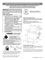
Rangedimensions:
• width:29”7/8(759mm)
• depth:24”13/64(614.9mm)
• height (without backguard): MIN 35” 21/32 (905.5 mm) - MAX 36”
11/32(923mm)
• backguard(height):3”(76mm)
Gas line opening: Wall-37/64”(14.5mm)fromtherightsidetocentre
ofrange;from5”7/16(138mm)to6”1/8(155.5mm)[dependingonfeet
regulation]fromtheoor.
Grounded outlet:shouldbelocated37/64”(14.5mm)fromtheleftside
tocentreofrange;from5”7/16(138mm)to6”1/8(155.5mm)[depen-
dingonfeetregulation]fromtheoor.
2. TherangeCANNOTbeinstalleddirectlyadjacenttosidewalls,tallcabi-
nets,tallappliances,orothersideverticalsurfacesabove36”(914mm)
high.
Theremustbeaminimumof11”13/16(300mm)sideclearancefromthe
rangetosuchcombustiblesurfacesTOTHELEFTorTOTHERIGHT
abovethe36”(914mm)highcountertop.
IMPORTANT: One side (left or right) above the 36” (914 mm) high
countertop must always be kept clear.
Island installation: Theremustbeaminimumof12”(305mm)clearan-
cefrom therearofthe backguardtosuchcombustible surfaceonthe
backoftherangeabovethe36”(914mm)highcountertop.
3. Themaximumuppercabinetdepthrecommendedis13”(330mm).Wall
cabinetabovetherangemustbeaminimumof30”(762mm)abovethe
countertopforawidthofminimum30”(762mm):ithastobecentered
withtherange.Sidewallcabinetsabovetherangemustbeaminimum
of18”(457mm)abovethecountertop.
installation
1
Fig. 1.1
3”
(76mm)
MIN35”21/32(905.5mm)
MAX36”11/32(923mm)
24”13/64
(614.9mm)
29”7/8
(759mm)

7
A
A
B
ASSEMBLING THE BACKGUARD
It is mandatory to install the backguard.
Assemblethebackguardasshowningure1.3:
• Screwthe2screws“A”interposingthespacers.
• Screwthecentralscrew“B”.
1
Fig. 1.3
GAS AND ELECTRIC CONNECTION
Fig. 1.2
Dottedlineshowingtheposition
oftherangewheninstalled
Areafor
ELECTRICAL
connection
Areafor
GASconnection
B
A
B
C
C
Ref. inch mm
A 5”7/16-6”1/8(*) 138-155.5(*)
B 14”3/8 365
C 37/64” 14.5
(*):Dependingonfeetregulation

8
B
G
E
D
C
F
A
A
B
C
E
D
F
G
A
A
PROXIMITY TO SIDE CABINETS
STANDARD INSTALLATION
Fig. 1.4b
Fig. 1.4a
OVEN VENT
Ref. inch mm
A 0” 0
B 36” 914
C 11”13/16 300
D 30”minimum 762minimum
E 18”minimum 457minimum
F 13”maximum 330maximum
G 20”minimum 500minimum
OVEN VENT
1

9
PROXIMITY TO SIDE CABINETS
ISLAND INSTALLATION
A
A
B
G
E
D
F
C
H
A
A
B
G
E
D
F
C
H
Fig. 1.5b
Fig. 1.5a
OVEN VENT
Ref. inch mm
A 0” 0
B 36” 914
C 11”13/16 300
D 30”minimum 762minimum
E 18”minimum 457minimum
F 13”maximum 330maximum
G 20”minimum 500minimum
H 12”minimum 305minimum
OVEN VENT
1

10
1
LEVELLING THE RANGE
Therangeisequippedwith4LEVELLINGFEETandmaybelevelledbyscrewingor
unscrewingthefeet(gs.1.6-1.7).
Itisimportanttoobservethedirectionsofgures1.6,1.8a,1.8b.
Fig. 1.8bFig. 1.8a
Fig. 1.7
Fig. 1.6
Suppliedwiththerange
inaseparatekit
Suppliedwiththerange
inaseparatekit
0”
0mm
+5/16”
+8mm
+5/16”
+8mm
+11/16”
+17.5mm
Fig. 1.9
Dotted line showing the position
oftherangewheninstalled
ANTI-TIPSTABILITY
DEVICEFIXING
Anti-tipstability
device
Rearleft
feetofrange
3”15/64
(82mm)
YOU MUST USE STABILITY
ANTI TIP BRACKET TO
PREVENT UNIT FROM
TIPPING.
ANTI-TIP STABILITY DEVICE INSTALLATION INSTRUCTIONS
1. Theanti-tipbrackethastobeattachedasshownongurebelow(onlyrearleftside),
ithastobexedontheoorORontherearwallbyno.4(four)suitablescrews(not
supplied).Alternativelytheanti-tipbracketcanalsobexedontheoorANDonthe
rearwallbyno.8(eight)suitablescrews(notsupplied).
2. Afterxingtheanti-tipbracket,sliderangeintoplace.Besuretherearleftfootslides
undertheanti-tipbracketattached.

11
1
INSTALLING THE COOKTOP FRONT GUARD
Toincreasetheclearancebetweenthefrontedgeofthecooktopandtheburnersitispossibletoinstallthecooktopfrontguardsupplied
withtheappliance.
IMPORTANT: To install/remove the guard it is necessary to remove the cooktop.
Attempting to install/remove the guard without disassembling the cooktop will result in permanent damage to the appliance.
Installthefrontguardasshowningure1.10:
1. Removethebackguard.
2. Removethepansupports,theburnercapsandtheamespreaders.
3. Unscrewcooktopxingscrews(“A”ingurebelow).
4. Removethedualburnerinneramespreader(“B”ingurebelow).
5. Removethecooktop(keepattentionnottodamagethegasketsttedabovetheburnercups-belowthecooktop).
6. Installthefrontguard“C”byinsertingthewireterminalsintotheproperholesabovethecontrolpanel(“D”ingurebelow).
7. Reassemblethecooktopandtheothercomponents(stepsfrom5to1).
Payspecialattentiontothegasketsttedabovetheburnercups
(belowthecooktop);iftheyaredamagedtheyshallbereplaced.
Fig. 1.10
A
A
A
A
A
A
B
B
C
D
D

12
gas connection
2
2. Pressure Regulator:
a. Allheavyduty,commercialtypecookingequipmentmusthaveapressureregulator
ontheincomingservicelineforsafeandefcientoperation,sinceservicepressure
mayuctuatewithlocaldemand.
Beforeinstallingtheregulatormountthe1/2”NPT(conical)maleconnectortothe
regulator(seepicture2.2).
Gasketsuppliedhastobeplacedbetween1/2”NPT(conical)connector/extension
pipemalepipetting(seepicture2.3).
Theregulatorsuppliedwiththisrangemustbeinstalledbeforeanygasconnections
aremade.
Usesuppliedpressureregulatoronly.
Gas supply line
Shuto valve
“open” position
To range
Explosion Hazard
Use a new CSA or UL approved
gas supply line.
Install a shut-off valve.
Securely tighten all gas connec-
tions.
If connected to LP, have a quali-
fied person make sure gas pres-
sure does not exceed 14" water
column.
Examples of a qualified person
include licensed heating per-
sonnel, authorized gas compa-
ny personnel, and authorized
service personnel.
Failure to do so can result in
death, explosion, or fire.
Fig. 2.1
Allgasconnectionsmustbemadeaccordingtonationalandlocalcodes.Thisgassupply
(service)linemustbethesamesizeorgreaterthantheinletlineoftheappliance.Sea-
lantonallpipejointsmustberesistanttotheactionofLP/Propanegas.
TherangeisequippedfortheusewithNATURALgas.Itisdesign-certiedbyCSAInter-
nationalforNATURALandL.P.gaseswithappropriateconversion.
Themodel/serialratingplate,locatedinsidethebottompivotingpanel,hasinformation
onthetypeofgasthatcanbeused.Ifthisinformationdoesnotagreewiththetypeof
gasavailable,check with the local gas supplier. See pagefrom16 to 18 for L.P. gas
conversioninstructions.
1. Manual Shut-off Valve(g:2.1):
Amanualshut-offvalvemustbeinstalledinanaccessiblelocationinthegaslineexternal
totheapplianceforthepurposeofturningonorshuttingoffgastotheappliance(InMas-
sachusettssuchshutoffdevicesshouldbeapprovedbytheBoardofStateExaminersof
Plumbers&GasFitters).
Thisvalveshouldbelocatedinthesameroomastherangeandshouldbeinalocation
thatallowseaseofopeningandclosing(inapositionwhereitcanbereachedquicklyin
theeventofanemergency).
Donotblockaccesstotheshutoffvalve.Thevalveisforturningonorshuttingoffgas
totheappliance.

13
2
LOCK
Arrow
PRESSURE REGULATOR INSTALLATION
STEP 1
Mountthe1/2”NPT(conical)maleconnectortothepressureregulatorand
tightenbyusingawrench.
Donotovertightentheconnector.
Overtighteningmaycrackregulator.
STEP 2
Assemblethe1/2”NPTconnector+pressureregulatorgrouptotheextensionpipeinterposingthegasketsupplied.
Theregulatorcovermustbeorientedtowardthefrontsideoftherange.
IMPORTANT:usetwowrenchestotightentheconnection.
Fig. 2.3
Fig. 2.2
Regulatorcover
Gasket

14
2
Fig. 2.4
GAS CONNECTION SPEFICICATION
Range
manifold
Manifold male pipe tting
1/2”Gcylindrical
(ISO228-1)male
1/2”Gcylindrical
(ISO228-1)female
Gasket
Extension
pipe female
pipe tting
Torange
1/2”Gcylindrical
(ISO228-1)female
Extension
pipe
1/2”Gcylindrical
(ISO228-1)male
Extension
pipe male
pipe tting
Gasket
Connector
1/2”NPT(conical)
male
1/2”NPT
female
Pressure
regulator
1/2”NPT
female
Tomains
connection
Arrow
WARNING: check the right positioning of the gas
regulator.
The arrow on the back of the gas regulator must be
oriented toward the connector.

15
2
b. Anyconversionrequiredmustbeperformedbyyourdealeroraqualiedlicen-
sedtechnicianorgasservicecompany.Pleaseprovidetheservicepersonwith
thismanualbeforeworkisstartedontherange.(Gasconversionsarethere-
sponsibilityofthedealerorenduser.)
c. ThisrangecanbeusedwithNATURALorLP/PROPANEgas.Itisshippedfrom
thefactoryadjustedforusewithNATURALgas.
d. Manifold pressure should be checked with a manometer and by operating as
belowdetailed:
• Removetheinjectorfromtherearleft(orrearright)burnerandmountthe
proper test point adapter which is available from the After-Sales Service
(seesidegureandthe“OPERATIONSTOBEPERFORMEDWHENSUB-
STITUTINGTHEINJECTORS”chapter).
• Turntherearleft(orrearright)burnercontrolknobtothemaximumposi-
tion.
• Presstheknobandkeepingitpressedcheckthemanifoldpressurewitha
manometer;NATURALgasrequires4.0”W.C.P.andLP/PROPANErequires
11.0”W.C.P.
• Incominglinepressureupstreamfromtheregulatormustbe1”W.C.P.hi-
gherthanthemanifoldpressureinordertochecktheregulator.
• Theregulatorusedonthisrangecanwithstandamaximuminputpressure
of1/2PSI(14.0”W.C.P).Ifthelinepressureisinexcessofthatamount,a
stepdownregulatorwillberequired.
e. Theappliance,itsindividualshut-offvalve,andpressureregulatormustbedi-
sconnectedfromthegassupplypiping system during any pressure testing of
thatsystematpressuresinexcessof1/2PSI(3.5kPa).
f. Theappliancemustbeisolatedfromthegassupplypipingsystembyclosingits
individualmanual shut-offvalveduringany pressuretestingof thegassupply
pipingsystemattestpressureequaltoorlessthan1/2PSI(3.5kPa).
3. Flexible Connections:
Iflocalcodespermit,CSAorULdesign-certied,exiblemetalapplianceconnector
isrecommendedforconnectingthisrangetothegassupplyline.DoNotkinkorda-
magetheexibleconnectorwhenmovingtherange.Thepressureregulatorhas1/2”
NPTfemalepipethreads.Youwillneedtodeterminethettingsrequired,depending
onthesizeofyourgassupplyline,exiblemetalconnectorandshutoffvalve.
4. Rigid Pipe Connections:
Ifrigidpipeisusedasagassupplyline,acombinationofpipettingsmustbeusedto
obtainanin-lineconnectiontotherange.Allstrainsmustberemovedfromthesupply
andfuellinessorangewillbelevelandinline.
• Usejointcompoundsandgasketsthatareresistanttoactionofnaturalorpropa-
negasonallmalepipethreads.
• Donotovertightengasttingwhenattachingtopressureregulator.Overtighte-
ningmaycrackregulator.
5. Leak Testing:
IMPORTANT:Leaktestingoftheapplianceshallbeconductedasfollows:
• Afternalgasconnectionismade,turnonmanualgasvalveandtestallcon-
nectionsingassupply piping and appliance for gas leaks withasoapywater
solution.Duringthistestallappliancegasvalveshavetobeclosed.
• Inordertoavoidpropertydamageorseriouspersonalinjury,neveruseaIighted
match.Ifaleakispresent,tightenjointorunscrew,applymorejointcompound,
tightenagainandretestconnectionforleak.
Fig. 2.5
TESTPOINTADAPTER
The Test Point adapter is available from the
After-SalesService.

16
2
Pressure
regulator
1
2
NATURAL GAS
REGULATION
LP/PROPANE
REGULATION
A
REGULATOR COVER
CONVERSION TO LP/PROPANE GAS (OR CONVERSION BACK TO THE
ORIGINAL GAS - NATURAL GAS)
Everyrangeisprovidedwithasetofinjectorsforthevarioustypesofgas.
Selecttheinjectorstobereplacedaccordingtothe“INJECTORSTABLE”.
Thenozzlediameters,expressedinhundredthsofamillimetre,aremarkedonthebodyofeachinjector.
CAUTION: Save the orices removed from the appliance for future use.
SETTING THE PRESSURE REGULATOR
Thepressureregulatoris accessible by opening the pivotingpanel(g. 2.6); the pressure regulator is
positionedontherearrightsideoftherange(g.2.7).
To set the pressure regulator(g.2.7):
1. Unscrewtheregulatorcover.
2. Unscrewthe“A”component,reverseandscrewitaccordingtotheLP/PROPANE(orNATURALGAS)
regulation.
Fig. 2.6
Fig. 2.7

17
2
OPERATIONS TO BE PERFORMED WHEN SUBSTITUTING THE
INJECTORS
• Removethepansupports,theburnercapsandtheamespreaders.
• Dualburneronly(g.2.9):Unscrewtheno.3xingscrews“A”andremovetheinner
crownamespreader“B”;thenunscrewtheno.2xingscrews“C”andremovethe
coverplate“D”.
• Usingawrenchsubstitutethenozzleinjectors“J
1
”,“J
2
”and“J
3
”(gs.2.8,2.9)with
thosemostsuitableforthekindofgasforwhichitistobeused.
• Dualburneronly(g.2.9):
Ret
thecoverplate“D”andscrewtheno.2xingscrews
“C”;thenrettheinnercrownamespreader“B”andscrewtheno.3xingscrews“A”
• Rettheamespreaders,theburnercapsandthepansupports.
The burner are conceived in such a way so as not to require the regulation of the
primary air.
SECOND ORIFICE
DEUXIEME ORIFICE
A
A
A
B
C
C
D
J
2
J
3
Fig. 2.9
J
1
Fig. 2.8
SEMI-RAPID BURNER
DUAL BURNER
INJECTORS TABLE
NOMINAL
POWER
REDUCED
POWER
LP/PROPANE
11”W.C.P.
NATURAL GAS
4”W.C.P.
BURNERS BTU/hr BTU/hr
Øinjector
[1/100mm]
Øinjector
[1/100mm]
Semirapid(SR) 8000 1500 85 139
Dual(D)
Innercrown 2100 1000
42(*)
115(**)
70(*)
200(**)
Inner&outercrown 17000 6500
(*) innercrown(“J
2
”ingure2.9)
(**) outercrown(“J
3
”ingure2.9)

18
Fig. 2.10
R
1
Regulationscrew(Semirapidburner)
R
2
Regulationscrew(Innercrownofdualburner)
R
3
Regulationscrew(Outercrownofdualburner)
R
1
R
3
R
2
SETTING THE BURNER MINIMUM
Whenswitchingfromonetypeofgastoanother,theminimumowratemustalsobecor-
rect:theameshouldnotgooutevenwhenpassingsuddenlyfrommaximumtominimum
ame.
Toregulatetheame(g.2.10)followtheinstructionsbelow:
Semirapid burner
• Lighttheburner.
• Setthegasvalveto“
LO”position(minimumrate).
• Removetheknob.
• Withathinscrewdriver,turntheregulationscrew“R
1
”untiladjustmentiscorrect.
Inside crown of DUAL burner
• LighttheDUALburner.
• Setthegasvalveto“
”position(minimumrateofinnercrown).
• Removetheknob
• Withathinscrewdriver,turntheregulationscrew“R
2
”untiladjustmentiscorrect.
Outside crown of DUAL burner
• LighttheDUALburner.
• Setthegasvalveto“
”position(minimumrateofinnerandoutercrowns).
• Removetheknob.
• Withathinscrewdriver,turntheregulationscrew“R
3
”untiladjustmentiscorrect.
For LP/PROPANE gas, tighten the adjustment screws completely.
Afterregulationrepeattheoperationsindicatedinparagraph“2.PRESSUREREGULA-
TOR”atpage12and15.
Iftherangehasbeendisconnectedandthenconnectedagaintothegassupplylinerepe-
attheoperationsindicatedinparagraph“5.LEAKTESTING”atpage15.
IMPORTANT:
• AfterconversiontoLP/PROPANEgashasbeencarriedoutafxnearthedataplate
theconversionlabelsuppliedandalsoafxaconversionlabelatpage3ofthisin-
structionmanual.
• Afterconversionbacktotheoriginalgas(NATURALGAS)hasbeencarriedoutre-
move,nearthedataplateandatpage3ofthisinstructionmanual,theLP/PROPANE
conversionlabels.Savethelabelsremovedforfutureuse.
2

19
electrical connection
3
WARNING
TO AVOID ELECTRICAL SHOCK HA-
ZARD, BEFORE INSTALLING THE
APPLIANCE, SWITCH POWER OFF
AT THE SERVICE PANEL AND LOCK
THE PANEL TO PREVENT THE PO-
WER FROM BEING SWITCHED ON
ACCIDENTALLY.
ELECTRICAL REQUIREMENTS
• Thisappliancemustbeproperlyinstalledandgroundedbyaqualiedtechnicianin
accordancewiththeNationalElectricalCodeANSI/NFPANo.70(latestedition)and
localelectricalcoderequirements.
• Thisappliancemaybeconnectedbymeansofpermanent“HardWiring”or“Power
SupplyCordkit”.
• Powersupplycordisnotsupplied,butitisavailablethroughyourlocalelectricsup-
plyhouse.
• Useonly3-conductoror4-conductorCSA/ULlistedrangecordratedat30ampswith
250Vminimumandprovidedwithringterminals.Thesecordsshouldbeprovided
withstrainrelieforconduitconnector.
Warning: Framegroundedthroughneutrallead.Ifusedin,
– Newbranch-circuitinstallations(1996NEC),
– Mobilehomes,
– Recreationalvehicles,or
– Inanareawherelocalcodesprohibitgroundingthroughneutral,usea4con-
ductorcordorconduit.
• The range must be connected to the proper electrical voltage and frequency as
speciedontheratingplate.
• Therangecanbeconnecteddirectlytothefuseddisconnect(orcircuitbreakerbox)
throughexible,counduitwithcopperoraluminiumwiring(withgroundingwire).
Allowtwotothreefeetofslackinthelinesothatitcanbemovedifservicingisever
necessary.
ELECTRICAL CONNECTION WITH POWER CORD
Usea3-wirepowersupplycordkitratedfor30amps-240-208/120voltswithclosedloop
terminalsandmarkedforusewithranges.
Wherelocalcodesdonotpermitgroundingthroughneutral,usea4-wirepowersupply
cord.
TheCSA/ULlistedcordmustbesecuredtotherangewithasuitablestrainreliefbra-
cket.
Theelectricalconnectionismadeattheterminalblock,whichislocatedbehindtheac-
cessdooronthebackoftherange.
ELECTRICAL CONNECTION WITH CONDUIT
Use1/2”(1.3cm)tradesizeCSA/ULlistedconduitwithaconduitclamp,16AWG/600
voltcopperconductorcolored redforline1andblackforline2and16AWG/600volt
copperconductor(or14AWG/600voltcopperconductorifgroundingthroughneutral)
coloredwhiteforneutralwithclosedloopterminalsmarkedforusewithranges.
Wherelocalcodesdonotpermitgroundingthroughneutral,useagreen14AWGcopper
conductorasdirectedinthe4-wireconnectordirections.
Theconduitmustbesecuredtotherangewiththestrainreliefbracket.
Theelectricalconnectionismadeattheterminalblock,whichislocatedbehindtheac-
cessdooronthebackoftherange.

20
3
3-Wire Power Cord Installation(SeeFigure3.2)
1. RemovetheTerminal Block Access Plateonthebackofthe
rangebyunscrewingthe4xingScrews(Figure3.1).
2. Check the correct positioning of thePower Cord Bracket as
pergure3.2.
3. AssemblethestrainreliefintheholeonPower Cord Bracket.
4. InsertthePower Cordthroughthestrainreliefandtighten.
5. Removethe3wireterminalnutsandwashersfromtheTermi-
nal Block.
6. PlugtheterminalholesofPower Cord.
TheNeutral or Ground WireofthePower Cordmustbecon-
nectedtotheneutralterminallocatedinthecenterofTerminal
Block.
The Power Wiresmustbeconnectedtotheoutsideterminals.
7. Plugwashersandtightennutssecurely.
DonotremoveGround strap.
8. ReassembletheTerminal Block Access Plateonthebackof
therangebyscrewingthe4xingScrews(Figure3.1).
4-Wire Power Cord Installation (SeeFigure3.3)
1. RemovetheTerminal Block Access Plateonthebackofthe
rangebyunscrewingthe4xingScrews(Figure3.1).
2. Check the correct positioning of thePower Cord Bracket as
pergure3.3.
3. AssemblethestrainreliefintheholeonPower Cord Bracket.
4. InsertthePower Cordthroughthestrainreliefandtighten.
5. Removethe3wireterminalnutsandwashersfromtheTermi-
nal Block.
6. RemovetheGround Strapfromtheframeofrangeandtermi-
nalbyremovingitsscrewandcuttingitasshowninFigure3.3.
7. PlugtheterminalholesofPower Cord.
TheNeutral WireofthePower Cordmustbeconnectedtothe
neutral terminal located in the center of Terminal Block; the
Power Wiresmustbeconnectedtotheoutsideterminals;the
Ground Wiremustbeattachedtotheframeofrangebyusing
the(Ground)identied
Grounding Screw.
8. Plugwashersandtightennutssecurely.
9. ReassembletheTerminal Block Access Plateonthebackof
therangebyscrewingthe4xingScrews(Figure3.1).
Terminal Block
Ground strap
Neutral Wire
Power Wires
Power Cord
Power Cord
Bracket
A: D=1” 9/64 (29 mm)
B: D=7/8” (22.5 mm)
A
B
Terminal Block
Cut Ground Strap
Power Cord
Bracket
Neutral Wire
Power Wires
Grounding Wire
Grounding
Screw
A: D=1” 9/64 (29 mm)
B: D=7/8” (22.5 mm)
Power Cord
A
B
Terminal Block
Access Plate
Screws
Screws
Fig. 3.1
Fig. 3.2
Fig. 3.3
/