Amana IC4 User manual

Type
User manual

This manual is also suitable for

IC4
Side-by-Side
Refrigerator
Ice Maker Kit
Installation and
Operating
Instructions
Keep these instructions for future reference. Be sure this
manual stays with the ice maker.
®
2
Parts
Use listed part numbers only when ordering replacement
parts. Part numbers are not used in installation
instructions.
Item Description Part
number
Quantity
1 Ice makers D7824703 1
2 Ice maker cover D7820401 1
3 Warning label A3036901 1
4 Ice maker arm 10901401 1
5 Stainless steel clip B5720301 1
6 Water fill tube extension A3127412 1
7 Ice maker wire harness D7826301 1
N/S Thermal fuse clip 10319801 1
8
5
/
8
" sheet metal screw M0211018 3
9 Button plug M0311301 2
10 Ice storage bucket D7806201 1
11 Stop pins M0560005 2
12 Sliding shelf D7839703 1
13 Sliding shelf decorative insert C8986123 1
14 Water valve D7712603 1
15 Water valve mounting
bracket
10496302 1
16
3
/
8
" thread cutting screw M0251015 3
17 Water valve coupling
assembly
10244903 1
18 Nylon nut and sleeve M0753001 1
19 ¼" plastic tubing B5705321 1
20 Anti-kink spring A1055101 1
21 Stainless steel insert A3223101 1
22 Tube clamp M0114003 1
23 “P” clamp M0104101 1
24 Plastic clip M0104101 1
25 Installation and operating
instructions
10527025 1
Introduction
CAUTION
!
To avoid personal injury or property damage, observe
all safety instructions.
Verify proper ice maker kit model, listed on wiring diagram
on back of refrigerator. Read entire manual before
installing kit. All necessary tools and materials must be
available prior to installation. Verify all listed parts are
included in kit. If parts are missing, contact source from
whom kit was purchased.
Mechanical experience is required to install kit.
Installation can take from 3 to 6 hours depending on
installer’s knowledge and skill.
If unable to solve a problem during installation, contact
an authorized Amana technician. Locate a Factory
Service Center or independent authorized technician by
calling 1-800-628-5782 inside U.S.A. and 1-319-622-
5511 outside U.S.A. Service is at owners expense.
Safety Instructions
WARNING
!
To avoid electrical shock which can cause severe
personal injury or death, disconnect power to
refrigerator before installing kit. After installing kit,
reconnect power.
CAUTION
!
To avoid property damage, observe the following:
Confirm water pressure to water valve is at least 20
pounds per square inch.
Start nuts by hand to avoid cross threading. Finish
tightening nuts with wrenches. Do not overtighten.
Check carefully for water leaks prior to returning
refrigerator to normal location and 24 hours after
connection.
Tools Required
3
/8" electric drill (ground fault protected)
3
/8" drill bit
1
/4" hex nut driver
1
/2" open-end wrenches (2)
Bucket
Gloves
Knife
Masking tape
Pliers
Screwdriver
Slip joint
Towel
1
2
3
4
5
7
8
10
6
9
11
12
13
14
15
16
17
18
19
20
21
22
24
23
25
3
Materials Required
Important
Before connecting ice maker, contact a plumber to
connect copper tubing to household plumbing in
compliance with local codes and ordinances.
Amana Appliances recommends using a saddle valve.
Do not use self-piercing valve. Amana Appliances is
not responsible for property damage due to improper
installation or water connection.
1
/4" (6 mm) outside diameter flexible copper tubing*.
*Length of copper tubing must reach from water supply
connection plus an additional 8' (3 m) for service loop
behind refrigerator. Tubing should be soft instead of rigid
and ends should be free of burrs.
Procedure
1. Turn off water supply to refrigerator.
CAUTION
!
To avoid property damage, protect soft vinyl or other
flooring with cardboard, rugs, or other protective
material when moving refrigerator.
2. Move refrigerator away from wall. Disconnect power.
3. Seal open end of copper tubing with masking tape to
keep inside of tubing clean. Route copper tubing up to
refrigerator through floor or interior wall behind
refrigerator providing
3
/8" (10 mm) holes as required.
Temperature surrounding copper tubing must be
above 35°F (1°C) to prevent water line from freezing.
4. Secure water valve mounting bracket behind square
collar on water valve inlet. Attach ground wire to
bracket with a
3
/8" (10 mm) cutting screw and a
1
/4"
hex nut driver.
A
B
A. Ground wire B.
3
/8" screw
Ground wire attachment
WARNING
!
To avoid electrical shock which can cause severe
personal injury or death, ground wire must be properly
attached to both bracket and water valve.
5. Remove lower horizontal and upper vertical cover on
rear of refrigerator cabinet by removing screws with a
1
/4" hex nut driver. On 22, 25, and 27 cubic foot
models, remove black plastic spacer with a
1
/4" hex
nut driver.
Cover removal
6. Remove electrical wiring plugs from retainer clamp on
lower rail of refrigerator cabinet. Connect electrical
wiring plugs to water valve spade terminals. Non-
polarized plugs connect to either terminal.
A
A. Electrical wiring plug
Electrical connection
7. Secure water valve to 2 predrilled holes in lower rail of
refrigerator cabinet with two
3
/8" (10 mm) long cutting
screws and a
1
/4" hex nut driver.
8. Insert plastic tubing from water valve under lower right
corner of metal cover. Carefully thread plastic tubing up
to water fitting. Plastic tubing should move freely under
top center portion of vertical cover. Route plastic tubing
under wiring harness between top of vertical cover and
water fitting.
9. Push stainless steel insert into open end of plastic
tubing. Stainless steel insert must be flush with end of
plastic tubing. Hold hose clamp open with pliers and
slide hose clamp over water fitting. Push end of plastic
tubing
5
/8" (16 mm) into water fitting stem and release
hose clamp. Confirm plastic tubing is secure by pulling
on plastic tubing.
A
B
A. Hose clamp B. Stainless steel insert
Water hose attachment to back of refrigerator
4
10. Replace upper vertical cover by placing cover on
refrigerator. Carefully tuck wires inside cover to avoid
pinching wires. Insert and tighten screws with a
1
/4"
hex nut driver.
11. Remove tape from end of copper tubing. Put end of
copper tubing into sink or bucket. Slightly turn on
water supply to refrigerator. Water will be under
considerable pressure. Allow water to run through
copper tubing for 1 minute to flush out copper tubing.
Shut off water supply to refrigerator when flushing is
complete.
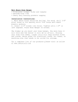
12. Slide nut and sleeve over end of copper tubing. Insert
copper tubing completely into adapter fitting. Check
adapter fitting to confirm rubber hose washer is in
place. Tighten adapter fitting by hand as much as
possible. Carefully tighten an additional
3
/8" (10 mm)
turn with pliers. Firmly connect tubing nut on copper
tubing to adapter fitting with two
1
/2" open-end
wrenches. Confirm copper tubing is secure by pulling
on copper tubing.
A
B
C
D
A. Hose washer B. Adaptor fitting
C. Sleeve D. Nut
Connecting copper tubing
13. Slightly turn on water supply to refrigerator and
check for leaks. Turn off water supply to refrigerator
and correct any leaks. Repeat this process until no
leaks are found. Completely turn on water supply to
refrigerator.
14. Slide ice service rack in freezer toward front of freezer
until screws are in middle of mounting holes. Gently
pull ice service rack away from freezer. Remove ice
service rack screws with a
1
/4" hex nut driver. Insert
plugs into screw holes.
15. Push up on lock tab to release water fill tube cover on
rear wall. Pull lower end of water fill tube cover away
from rear wall. Lift up slightly to release water fill tube
cover from upper hinges. Remove and discard water
fill tube cover.
16. Remove top freezer shelf.
17. Remove 3 screws from white air duct cover on rear
wall with a
1
/4" hex nut driver. Remove electrical cap
on rear wall with a screwdriver. Discard screws and
electrical cap.
18. Slide water fill tube extension over water inlet tube on
rear wall. Water fill tube extension must fit tightly and
be even with hole in rear wall so water cannot leak
into freezer.
A
A. Water inlet tube
Water inlet tube installation
19. Remove ice maker from shipping carton. Discard
packing material. Ice maker is shipped with arm
down. This is correct for ice production. Do not force
ice maker arm down or up.
20. Slide stainless steel clip over rear wall of ice maker
water cup.
A
B
A. Stainless steel clip B. Water cup
Stainless steel clip installation
21. Start two
5
/8" (16 mm) long sheet metal screws in top
holes on rear wall with a
1
/4" hex nut driver. Leave
heads out approximately
3
/8" (10 mm).
22. Hold ice maker in position. Ice maker can only be
installed one way. Do not drill additional holes. Insert
wire harness plug into receptacle on rear wall. Slide
ice maker hangers over sheet metal screws. Ease
water cup toward end of water fill tube extension.
Water fill tube extension fits under stainless steel
clip. Water fill tube extension must not be kinked.
Water fill tube extension should extend approximately
3
/8" (10 mm) into ice maker water cup and must be
secured under stainless steel clip.
Ice maker Installation
23. Install remaining
5
/8” (16 mm) long sheet metal screw
under ice maker and tighten all 3 screws with a
1
/4"
hex nut driver.
5
32. Create service loop using extreme care to avoid
kinks. Secure copper tubing with a “P” clamp
and back horizontal cover screw. Copper tubing
must not extend
3
/8" (9 mm) beyond back.
A
A. "P" clamp
Secure service loop
33. Connect power to refrigerator. Move refrigerator in
place and level if necessary.
Operating Instructions
Confirm ice bucket is in place and ice maker arm is
down.
A
B
C
A. Locked position B. Ice maker arm
C. Down position
After freezer section reaches normal temperature, ice
maker fills with water and begins operating. Allow 24–
48 hours after installation before first harvest of ice. Ice
maker produces 7 to 9 harvests of ice in a 24-hour
period under ideal conditions.
After ice is formed, ice maker drops ice cubes into
ice storage bucket. During ice production, ice maker
arm raises and lowers. When ice storage bucket is full,
ice maker arm turns ice maker off. Discard first 3
harvests of ice after initial ice production and after
extended periods of non-use.
Stop ice production by lifting ice maker arm. A definite
click is heard when off position is reached. Ice maker
arm will remain in that position until pushed down.
CAUTION
!
To avoid damage to ice maker, observe the following:
Do not force ice maker arm down or up.
Do not place or store anything on ice maker or in ice
storage bucket.
24. Built-In Models (SB******)
Remove and discard button plugs above ice maker
with a putty knife covered with masking tape.
All Other Models
Remove and discard button plugs below ice maker
with a putty knife covered with masking tape.
25. Confirm stop pin locking fingers are unlocked. Center
drive pin must extend
1
/2" (13 mm) on opposite side of
locking fingers. If not pull out center drive or use a
screwdriver to push center drive pin out
1
/2" (13 mm).
Stop pin inspection
26. Built-In Models (SB******)
Push locking fingers into button plug holes above ice
maker.
All Other Models
Push locking fingers into button plug holes below ice
maker.
27. Tap center drive pins into stop pin sleeves with
screwdriver handle. Locking fingers should expand
inside wall, wedging locking fingers firmly in place.
End of drive pins must be flush with end of stop pin
sleeves.
28. Replace freezer shelf.
29. Position back of ice storage bucket up and over stop
pins to avoid overfilling bucket.
30. Remove paper backing from sliding shelf decorative
insert. Carefully position sliding shelf decorative insert
on front of sliding shelf then press on. Place sliding
shelf on top of ice storage bucket.
31. Check for leaks at household plumbing connection
and water valve. Correct any leaks. Replace lower
cover by placing cover on refrigerator. Carefully tuck
wires inside cover to avoid pinching wires. Insert and
tighten screws with a
1
/4" (6 mm) nut driver. On 22,
25, and 27 cubic foot models, place black plastic
spacer on refrigerator. Insert and tighten screws
with a
1
/4" (6 mm) nut driver.
6
Before Calling For Service
Allow ice maker 1 overnight period to make ice before
assuming a difficulty exists.
If ice maker is not producing ice
Confirm ice maker arm is down.
Confirm household water supply is reaching water
valve.
Confirm ice maker wiring harness plug is completely
inserted into electrical receptacle.
Check for kinks in copper or plastic tubing. Remove
kinks or replace tubing.
Check electrical connections to water valve coil.
Confirm freezer is operating at proper temperature.
If ice maker is not producing enough ice
Ice maker produces 7 to 9 harvests of ice in a 24-hour
period under ideal conditions.
See above section.
If ice maker makes unfamiliar sounds
These may be normal. Refer to
“Normal Operating
Sounds”
section in Owner's Manual.
Warranty
Ice Maker
Full One Year Warranty
First Year
Manufacturer will repair or replace, free of charge, any part which is defective due to workmanship or
materials.
Warranty Limitations
Begins at date of original purchase.
Applies to product used within the United States
or in Canada if product has Canadian Standards
Association listing when shipped from the factory.
Service must be performed by an authorized
Amana
®
technician.
Warranty Is Void If
Product is used on a commercial, rental or leased
basis.
Product has defect or damage due to an accident,
fire, flood, connection to an improper electrical or
water supply, lightning, product alteration, shipping
and handling, or other conditions beyond the
control of Amana Appliances
Product is improperly installed or used.
Owner's Responsibilities
Provide proof of purchase (sales receipt).
Provide normal care and maintenance. Replace
owner replaceable items where directions appear
in Owner's Manual and Installation Instructions.
Make product reasonably accessible for service.
Pay for premium service costs for service outside
technician's normal business hours.
Pay for service calls related to product installation
or usage.
In no event shall Amana Appliances be liable for
incidental or consequential damages*
*This warranty gives you specific legal rights and you
may have others which vary from state to state. For
example, some states do not allow the exclusion or
limitation of incidental or consequential damages so
this exclusion may not apply to you.
7
Part No. 10527037
Printed in U.S.A.
Ó 1998 Amana Appliances
Amana, Iowa 52204
  • Page 1 1
  • Page 2 2
  • Page 3 3
  • Page 4 4
  • Page 5 5
  • Page 6 6
  • Page 7 7
  • Page 8 8

Amana IC4 User manual

Type
User manual
This manual is also suitable for

Ask a question and I''ll find the answer in the document

Finding information in a document is now easier with AI