Page is loading ...

USER GUIDE & SERVICE MANUAL
Outdoor Collection
●
UOCR115
●
15” Crescent Ice Maker

USER GUIDE & SERVICE MANUAL
u-line.com
Table of Contents
Intro
Safety
Safety and Warning
Disposal And Recycling
Installation
Environmental Requirements
Electrical
Cutout & Product Dimensions
Side by Side Installation
Water Hookup
Anti-Tip Bracket
General Installation
Grille Installation
Door Swing
Door Adjust
Maintenance
Cleaning
Cleaning Condenser
Extended Non-Use
Operating Instructions
First Use
Ice
Airflow and Product Loading
Service
Troubleshooting
Product Liability
Warranty Claims
Parts
Ordering Replacement Parts
System Diagnosis Guide
Compressor Specifications
Troubleshooting Extended
Defrost
Replace Ice Maker
Warranty

USER GUIDE
u-line.com
Introduction
WELCOME TO U-LINE
Congratulations on your U-Line purchase. Your product comes from a company with over ve decades of premium modular ice
making, refrigeration, and wine preservation experience. U-Line creates products focused on functionality, style, and inspired
innovations — paying close attention to even the smallest details. Applications include residential, outdoor, ADA height
compliant, marine, and commercial. Complete product categories include Beverage Centers, Wine Refrigerators, Ice Machines,
Refrigerators, Freezers, and Dispensers.
Our advanced refrigeration systems, large and exible capacities, and Built-In to Stand Out
®
clean integrated look allow you
to preserve the right product, in the right place, at the right temperature. Since 2014, U-Line has been part of the Middleby
family of brands. All products are designed, engineered, and assembled in Milwaukee, Wisconsin, USA, and select products
are available worldwide.
PRODUCT INFORMATION
Looking for additional information on your product? User Guides, Spec Sheets, CAD Drawings, Compliance Documentation,
and Product Warranty information are all available for reference and download at u-line.com.
PROPERTY DAMAGE / INJURY CONCERNS
In the unlikely event property damage or personal injury is suspected related to a U-Line product, please take the following
steps:
1. U-Line Customer Care must be contacted immediately at +1.414.354.0300.
2. Service or repairs performed on the unit without prior written approval from U-Line is not permitted. If the unit has been
altered or repaired in the eld without prior written approval from U-Line, claims will not be eligible.
GENERAL INQUIRIES
U-Line Corporation
8900 N. 55th Street
Milwaukee, Wisconsin 53223 USA
Monday - Friday 8:00 am to 4:30 pm CST
T: +1.414.354.0300
Email: sales@u-line.com
u-line.com
CONNECT WITH US
SERVICE & PARTS ASSISTANCE
Monday - Friday 8:00 am to 4:30 pm CST
T: +1.414.354.0300
Service Email: onlineservice@u-line.com
Parts Email: onlineparts@u-line.com
Designed, engineered and assembled in WI, USA
3

USER GUIDE
u-line.com
Safety and Warning
Safety and Warning
NOTICE
Please read all instructions before installing,
operating, or servicing the appliance.
Use this appliance for its intended purpose only and follow
these general precautions with those listed throughout this
guide:
SAFETY ALERT DEFINITIONS
Throughout this guide are safety items labeled with a
Danger, Warning, or Caution based on the risk type:
Danger means that failure to follow this safety
statement will result in severe personal injury or
death.
Warning means that failure to follow this safety
statement could result in serious personal injury
or death.
Caution means that failure to follow this safety
statement may result in minor or moderate
personal injury, property, or equipment damage.
CALIFORNIA PROPOSITION 65
This product contains chemicals known to the
state of California to cause cancer and birth
defects or other reproductive harm.
www.P65warnings.CA.gov
This equipment is to be installed with adequate
backow protection to comply with applicable
federal, state and local codes.
DANGER
!
WARNING
!
CAUTION
!
CAUTION
!
WARNING
!
4

USER GUIDE
u-line.com
Disposal and Recycling
Disposal and Recycling
RISK OF CHILD ENTRAPMENT. Before you throw
away your old refrigerator or freezer, take o
the doors and leave shelves in place so children
may not easily climb inside.
If the unit is being removed from service for disposal,
check and obey all federal, state, and local regulations
regarding the disposal and recycling of refrigeration
appliances, and follow these steps completely:
1. Remove all consumable contents from the unit.
2. Unplug the electrical cord from its socket.
3. Remove the door(s)/drawer(s).
DANGER
!
5

USER GUIDE
Environmental Requirements
u-line.com
Environmental Requirements
This unit is designed to operate between 50°F (10°C) and
100°F (38°C). Higher ambient temperatures may reduce
the unit’s ability to reach low temperatures and/or reduce
ice production on applicable models.
For best performance, keep the unit out of direct sunlight
and away from heat generating equipment.
In climates where high humidity and dew points are
present, condensation may appear on outside surfaces.
This is considered normal. The condensation will
evaporate when the humidity drops.
CAUTION
!
Damages caused by ambient temperatures of
40°F (4°C) or below are not covered by the
warranty.
6

USER GUIDE
Electrical
u-line.com
Electrical
WARNING
!
SHOCK HAZARD — Electrical Grounding
Required. Never attempt to repair or perform
maintenance on the unit until the electricity has
been disconnected.
Never remove the round grounding prong from
the plug and never use a two-prong grounding
adapter.
Altering, cutting or removing power cord,
removing power plug, or direct wiring can cause
serious injury, fire, loss of property and/or life,
and will void the warranty.
Never use an extension cord to connect power to
the unit.
Always keep your working area dry.
NOTICE
Electrical installation must observe all state and
local codes. This unit requires connection to a
grounded (three-prong), polarized receptacle
that has been placed by a qualified electrician.
The unit requires a grounded and polarized 115 VAC,
60 Hz, 15A power supply (normal household current). An
individual, properly grounded branch circuit or circuit
breaker is recommended. A GFCI (ground fault circuit
interrupter) is usually not required for fixed location
appliances and is not recommended for your unit because
it could be prone to nuisance tripping. However, be sure
to consult your local codes.
See CUTOUT & PRODUCT DIMENSIONS for recommended
receptacle location.
7

USER GUIDE
Cutout & Product Dimensions
u-line.com
Cutout & Product Dimensions
PREPARE SITE
Your U-Line product has been designed for either free-
standing or built-in installation. When built-in, your unit
does not require additional air space for top, sides, or
rear. However, the front grille must NOT be obstructed,
and clearance is required for an electrical connection in
the rear.
CAUTION
!
Unit can NOT be installed behind a closed
cabinet door.
CUTOUT DIMENSIONS
*15” cutout width sufficient if door protrudes beyond
adjacent cabinetry
PRODUCT DIMENSIONS
REAR
24"
(610 mm)
1-1/2" (38 mm)
15-1/4"
(387 mm)
34-1/4"
(870 mm)
to
35"
(889 mm)
Preferred location
for electrical
outlet is in
adjacent
cabinet.
7"
(178 mm)
5/8"
(16 mm)
14 ⁄”
(379 mm)
3 ⁄”
(91 mm)
28”
(711 mm)
34 ⁄”
to 35 ⁄”
(867 mm
to
892 mm)
Power Cord
6 ft (183 cm)
1 ½”
(38 mm)
3 ½”
(76 mm)
1 ⁄”
(48 mm)
11 ⁄”
(291 mm)
15 ½”
(394 mm)
20 ⁄”
(525 mm)
14 ⁄”
(365 mm)
22 ¼”
(562 mm)
24 ⁄”
(613 mm)
1” (25 mm)
TOP
FRONT
SIDE
8

USER GUIDE
Side-by-Side Installation
u-line.com
Side-by-Side Installation
Two units may be installed side-by-side.
Cutout width for a side-by-side installation is the cutout
dimension of a single unit times two.
No trim kit is required. However, 1/4" (6 mm) of space
needs to be maintained between the units to ensure
unobstructed door swing.
Units must operate from separate, properly grounded
electrical receptacles placed according to each unit’s
electrical specifications requirements.
Side-by-Side Installation with Bracket
1. Slide both units out so screws on top of units are easily
accessible.
2. Remove screws as shown below.
3. Place bracket over holes and attach to unit with two
screws removed in step 2 using a T-25 Torx driver.
Tighten screws fully.
4. Gently push units into position. Be careful not to
entangle the electrical cord or water line, if applicable.
5. Re-check the leveling, from front to back and side to
side. Make any necessary adjustments. The unit’s top
surface should be approximately 1/8" (3 mm) below
the countertop.
9

USER GUIDE
Water Hookup
u-line.com
Water Hookup
PREPARE PLUMBING
The water valve uses a standard 1/4" (6.35 mm)
compression fitting. U-Line recommends using accessory
water hook up kit – part # 80-54674-00. The kit includes a
10' (3 m) braided flexible water supply line and a brass
hose fitting.
CAUTION
!
Plumbing installation must observe all state and
local codes. All water and drain connections
MUST BE made by a licensed/qualified plumbing
contractor. Failure to follow recommendations
and instructions may result in damage and/or
harm.
Water Supply Connection
When connecting the water supply, please note the
following:
• Before installing the unit and connecting to the cold
water supply, review the local plumbing codes.
• The water pressure should be between 20 and 120 psi
(138 and 827 kPa).
• The water line MUST have a shut-off valve in the
supply line.
• The water line should be looped into 2 coils. This will
allow the unit to be removed for cleaning and servicing.
Make certain that the tubing is not pinched or damaged
during installation.
WARNING
!
Connect to potable water supply only.
CAUTION
!
Do not use any plastic water supply line. The line
is under pressure at all times. Plastic may crack
or rupture with age and cause damage to your
home.
Do not use tape or joint compound when
attaching a braided flexible water supply line
that includes a rubber gasket. The gasket
provides an adequate seal – other materials
could cause blockage of the valve.
Failure to follow recommendations and
instructions may result in damage and/or harm,
flooding or void the product warranty.
Use new hose set. Do not reuse old hose set.
CAUTION
!
Turn off water supply and disconnect electrical
supply to unit prior to installation.
Use caution when handling back panel. The
edges could be sharp.
1. Turn off water supply and disconnect electrical supply
to product prior to attempting installation.
2. Remove the back panel.
10

USER GUIDE
Water Hookup
u-line.com
3. Locate water valve inlet.
4. Break away filler feature
in bushing with flat
screwdriver.
5. Thread water line
through back panel hole
(with bushing).
6. Locate water valve inlet
and connect to valve.
7. Turn on water supply
and check for leaks.
8. Reinstall back panel.
9. Install retaining clip.
Remove
ZLWKɠDW
screwdriver
11

USER GUIDE
u-line.com
Anti-Tip Bracket
Anti-Tip Bracket
1. Slide unit out so screws on top of unit are easily
accessible.
2. Remove the two screws from the opposite side of the
hinge assembly using a T-25 Torx driver (see below).
3. Place bracket over holes and attach to unit with two
screws removed in step 2 using a T-25 Torx driver.
Tighten screws fully.
4. Gently push unit into position. Be careful not to
entangle the electrical cord or water line, if applicable.
5. Check to be sure the unit is level from front to back
and side to side. Make any necessary adjustments.
The unit’s top surface should be approximately 1⁄8”
(3 mm) below the countertop.
6. Secure bracket into adjoining surface.
12

USER GUIDE
u-line.com
General Installation
General Installation
LEVELING INFORMATION
1. Use a level to
conrm the unit is
level. Level should
be placed along top
edge and side edge
as shown.
2. If the unit is not level, adjust the legs on the corners of
the unit as necessary.
3. Conrm the unit is level after each adjustment and
repeat the previous steps as needed.
INSTALLATION TIP
If the room oor is higher than the oor in the cutout
opening, adjust the rear legs to achieve a total unit rear
height of
1⁄8” (3 mm) less than opening’s rear height.
Shorten the unit height in the front by adjusting the front
legs. This allows the unit to be gently tipped into the
opening. Readjust the front legs to level the unit after it is
correctly positioned in the opening.
INSTALLATION
1. Plug in the power/electrical cord.
2. Gently push the unit into position. Be careful not
to entangle the cord or water and drain lines, if
applicable.
3. Re-check the leveling, from front to back and side to
side. Make any necessary adjustments. The unit’s top
surface should be approximately
1⁄8” (3 mm) below
the countertop.
4. Install the anti-tip bracket.
5. Remove interior packing material and wipe out the
inside of the unit with a clean, water-dampened cloth.
1
Turn to Adjust
13

USER GUIDE
Grille Installation
u-line.com
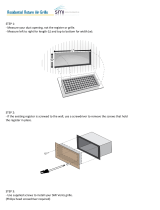
Grille Installation
REMOVING AND INSTALLING GRILLE
WARNING
!
Disconnect electric power to the unit before
removing the grille.
When using the unit, the grille must be installed.
Removing the grille
1. Disconnect power to the unit.
2. Remove three screws (1).
3. Slide grille (2) away from bottom hinge and remove
grille from unit.
Installing the grille
1. Align notch (3) in grille with center screw on bottom
hinge and slide grille behind hinge.
2. Use two screws to secure grille to cabinet.
3. Reconnect power to the unit.
2
3
1
14

USER GUIDE
Door Swing
u-line.com
Door Swing
Units have a zero clearance for the door to open 90°,
when installed adjacent to cabinets.
Stainless Steel models require 2-1/8" (54 mm) door
clearance to accommodate the handle if installed next to a
wall.
Wall
90°
Door Swing
2-1/8" Min.
(54 mm)
15

USER GUIDE
u-line.com
Door Adjustments
Door Adjustments
HINGE COVER
Hinge cover included with the literature bag is optional.
To install hinge cover:
1. Press hinge cover squarely over hinge.
DOOR ALIGNMENT AND ADJUSTMENT
Align and adjust the door if it is not level or is not sealing
properly. If the door is not sealed, the unit may not cool
properly, or excessive frost may form in the interior.
NOTICE
Properly aligned, the door’s gasket should be
rmly in contact with the cabinet all the way
around the door (no gaps). Carefully examine the
door’s gasket to ensure that it is rmly in contact
with the cabinet. Also make sure the door gasket
is not pinched on the hinge side of the door.
To align and adjust the door:
1. Gently pry o hinge cover from top of unit.
2. Loosen (do not remove) top and bottom hinge screws
using a Torx T-25 screwdriver on the top and a 1/4”
socket on the bottom.
3. Align door squarely with cabinet.
4. Make sure gasket is rmly in contact with cabinet all
the way around the door (no gaps).
5. Tighten bottom hinge screws.
6. Tighten top hinge screws and replace hinge cover.
REVERSING THE DOOR
Location of the unit may make it desirable to mount the
door on the opposite side of the cabinet.
The hinge hardware will be removed and reinstalled on the
opposite side of the cabinet.
TO REVERSE THE DOOR
Remove top hinge and door:
1. Remove hinge cover from top of unit
2. Hold door to keep it from falling.
3. Remove top hinge from cabinet using a Torx T-25
screwdriver to remove three screws.
Hinge Cover
16

USER GUIDE
u-line.com
Door Adjustments
4. Remove door by tilting forward and lifting door o
bottom hinge. Retain shoulder washers; they will be
reused.
5. Remove three screws from hinge holes on the
opposite side. Reinstall into holes where the hinge was
removed. Take care not to scratch cabinet.
Remove bottom hinge:
1. Remove bottom hinge from cabinet using a 1/4”
socket.
2. Remove corresponding screws on opposite side of
cabinet. On some models there may be a nut behind
one or both screws on either side.
Install bottom hinge:
Install two or three screws, depending on model. Replace
nuts if used.
Prepare door for reinstallation:
1. Remove outside gasket.
2. Rotate gasket 180
º and press firmly into the gasket
channel starting at the corners.
3. Reposition inside gasket.
a.
b.
c. Using a flat tool, such as a putty knife, gently pry
off inside gasket.
d. Rotate door 180
º
and
line up top edge of gasket to
marks on door and rmly press gasket into place.
(If the original adhesive no longer holds the gasket
in place, it may be necessary to apply a strip of
two-sided tape.)
Install top hinge and door:
1. Remove pivot screw from hinge, ip hinge over, and
install the pivot screw in the same hole from the
opposite surface.
2. Lift the door onto the bottom hinge.
3. Align edge of the hinge with the outer edge of the unit.
4. Tighten three screws and replace hinge cover.
Align and adjust the door:
Align and adjust the door (see DOOR ALIGNMENT AND
ADJUSTMENT)
Install grille
Before rotating door,
measure distance from
top of outside gasket to
top of inside gasket.
Measure the same
distance up from the
outside edge of the
gasket and place a light
mark on each side of
door.
Place a mark
on each side
Top of Door
a
b
Top Hinge
Right Side
Top Hinge
Left Side
Pivot
Screw
17

USER GUIDE
First Use
u-line.com
First Use
Initial startup requires no adjustments.
NOTICE
U-Line recommends discarding the ice produced
during the first two to three hours of operation
to avoid possible dirt or scale that may dislodge
from the water line.
To turn the unit on or off:
Press the rocker switch located inside the door on the
front panel, or behind the grille.
OFF
ON
18

USER GUIDE
Ice
u-line.com
Ice
ICE MAKER OPERATION
When the ice bucket is full, the ice making mechanism will
shut off. However, the refrigeration system will continue
to cool and maintain the ice supply.
NOTICE
Do not place cans or bottles in the ice
compartment because they will freeze.
To turn off ice production: Raise the bin arm into
an upright and locked position. The unit will preserve
temperature for ice storage.
NOTICE
If not intending to use the ice maker, turn the
water supply valve off. It is also important to
raise the bin arm of the ice maker (see above).
Failure to raise the bin arm may result in damage
to the water valve.
Certain sounds are normal during the unit’s operation. You
may hear the compressor or fan motor, the water valve,
or ice dropping into the ice bucket.
CAUTION
!
NEVER use an ice pick, knife or other sharp
instrument to separate cubes. Shake the ice
bucket instead.
During periods of limited use or high ambient
temperatures, it is common for cubes to fuse together.
Gently shake the bucket to break apart cubes. If not using
the ice maker regularly, empty the ice bucket periodically
to ensure fresh cubes.
It is normal for cubes to appear cloudy. The cause is air
trapped in the water because of fast freezing. It is not
caused by the health, taste or chemical make up of the
water. It is the same air that is in every glass of water you
drink.
Remove the ice bucket for emptying and cleaning. To
remove the ice bucket, raise the bin arm and remove the
bucket from the ice compartment. Use the ice bucket for
ice storage only.
OFF
ON
19

USER GUIDE
Ice
u-line.com
ICE MAKER ADJUSTMENT
Ice Cube Thickness Adjustment
Interval - As Required
On ice maker equipped models, adjust the cube size by
changing water amount injected into the ice maker
assembly as follows:
1. Remove the ice maker assembly cover (1).
2. Find the adjusting screw on the ice maker assembly
control box (2). The adjusting screw is just below the
minus (-) and plus (+) signs on the control box.
CAUTION
!
Too large of an adjustment to the screw can
cause the water to overflow the ice maker and
can cause property damage.
3. Turn the adjusting screw toward the minus (-) sign
(clockwise) for smaller cubes or toward the plus (+)
sign (counterclockwise) for larger cubes.
4. Install the ice maker assembly cover.
ADJUSTING ICE HARVEST
1. Remove the front grille (see GRILLE-PLINTH
INSTALLATION).
2. Using a flat tip screwdriver, turn the adjusting screw
(3) a small increment clockwise for a COLDER setting
(slower ice production) or counterclockwise for a
WARMER setting (faster ice production).
3. Reinstall the front grille (two screws).
1
2
C
O
L
D
E
R
Warmer Colder
3
1
2
20
/