
Technical Reference
WFM6100, WFM7000, and WFM7100
Waveform Moni tors With Op tion FP
Specifications and Performance Verification
071-2291-00
This document applies to firmware version 3.0.X.
www.tektronix.com

Copyright © Tektronix. All rights reserved. Licensed software products are owned by Tektronix or its subsidia ries or
suppliers, and are protected by na tional copyright laws and international treaty provisions.
Tektronix products are covered by U.S. and foreign patents, issued and pending. Information in this publication supercedes
that in all previously published material. Specifications and price change privileges reserved.
TEKT RONIX and TEK are registered trademarks of Tektronix, Inc.
Contacting Tektronix
Tektronix, Inc.
14200 SW Karl Braun Drive
P.O. Box 500
Beaverton, OR 97077
USA
For product information, sales, service, and technical support:
H In North America, call 1-800-833-9200.
H Worldwide, visit www.tektronix.com to find contacts in your area.

Warranty 2
Tektronix warrants that this product will be free from defects in materials and workmanship for a period of one (1)
year from the date of shipm ent. If any such product proves defecti ve duri ng this warranty period, Tektronix, at its
option, either will repair the defective product without charge for parts and labor, or will provi de a replacement in
exchange for the defective product. Parts, modules and replacement products used by Tektronix for warranty work
may be new or reconditioned to like new performance. All replaced parts, modules and products become the
property of Tektronix.
In order to obtai n service under this warranty, Customer must notify Tektronix of the defect before the expiration
of the warranty period and make suitable arrangements for the performance of service. Customer shall be
responsible for packaging and shipping the defective product to the servic e center designated by Tektronix, with
shipping charges prepaid. Tektronix shall pay for the return of the product to Customer if the shipment is to a
location within the country in which the Tektronix service center is located. Customer shall be responsible for
paying all shipping charges, duties, ta xes, and any other charges for products returned to any other locations.
This warranty shall not appl y to any de fect, failure or damage caused by i mproper use or improper or inadequate
maintenance and care. Tektronix shall not be obligated to furnish service under this warranty a) to repair damage
resulting from attempts by personnel other than Tektronix representative s to install, repair or service the product;
b) to repair damage resulting from improper use or conne ction to incompatible equipment; c) to repair any
damage or malfunction caused by the use of non-Tektronix supplies; or d) to service a product that has been
modified or integrated with othe r product s whe n the effect of such modification or integration increases the time
or difficulty of servicing the product.
THIS WARRANTY IS GIVEN BY TEKTRONIX WITH RESPECT TO THE PRODUCT IN LIEU OF ANY
OTHER WARRANTIES, EXPRESS OR IMPLIED. TEKTRONIX AND ITS VENDORS DISCLAIM ANY
IMPLIED WARRANTIES OF MERCHANTABILITY OR FITNESS FOR A PARTICULAR PURPOSE.
TEKTRONIX’ RESPONSIBILITY TO REPAIR OR REPLACE DEFECTIVE PRODUCTS IS THE SOLE AND
EXCLUSIVE REMEDY PROVIDED TO THE CUSTOMER FOR BREACH OF THIS WARRANTY.
TEKTRONIX AND ITS VENDORS WILL NOT BE LIABLE FOR ANY INDIRECT , SPECIAL, INCIDENTAL,
OR CONSEQUENTIAL DAMAGES IRRESPECTIVE OF WHETHER TEKTRONIX OR THE VENDOR HAS
ADVANCE NOTICE OF THE POSSIBILITY OF SUCH DAMAGES.


WFM6100, WFM7000, and WFM7100 Waveform Monitors With Option FP
i
Table of Contents
General Safety Summary v...................................
Service Safety Summary vii....................................
Environmental Con siderations ix...............................
Preface xi...................................................
Related User Documents xi..........................................
Related Reference Documents xii......................................
Specifications 1--1.............................................
Electrical Specifications 1--1...........................................
Physical Specifications 1--39............................................
Certifications and Compliances 1--40.....................................
Supported Input Formats and Allowed References 1--42......................
Alarms 1--45.........................................................
Performance Verification 2--1...................................
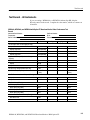
Test Records 2--3....................................................
Test Record -- Function Tests 2--3.......................................
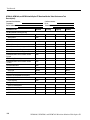
Test Record -- All Instruments 2--5......................................
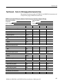
Test Record -- Tests for SD-Equipped Instruments Only 2--7..................
T e s t R e c o r d -- O p t i o n C P S o n l y 2 -- 9.....................................
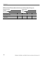
Test Record -- Options AD and DDE only 2--10.............................
Test Record -- Option DS only 2--15......................................
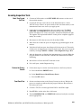
Incoming Inspection 2--19.......................................
Required Equipment 2--19..............................................
Incoming Inspection Tests 2--21.........................................
V ideo and General Performance Verification Procedures 2--41.........
Required Equipment 2--41..............................................
Instrument Tests 2--43.................................................
Tests for SD-Equipped Instruments Only 2--60..............................
Tests for Option-CPS-Equipped Instruments Only 2--74......................
Signal Source Characterization for Eye Signal Bandwidth 2--84................
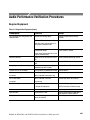
Audio Performance Verification Procedures 2--87....................
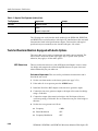
Required Equipment 2--87..............................................
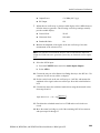
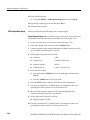
Tests for Waveform Monitors Equipped with Audio Options 2--88.............
Additional Tests for Instruments equipped with Options AD and DDE 2--97......

Table of Contents
ii
WFM6100, WFM7000, and WFM7100 Waveform Monitors With Option FP
List of Figures
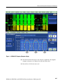
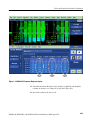
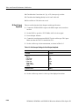
Figure 1-- 1: VM5000 HD Frequency Response display 2--47...........
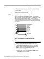
Figure 1--2: Wiring diagram for LTC input/Ground Closure cable 2--55.
Figure 1--3: VM5000 SD Frequency Response display 2--63...........
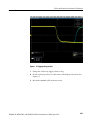
Figure 1--4: Trigger polarity positive 2--67..........................
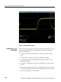
Figure 1--5: Trigger polarity negative 2--68.........................

Table of Contents
WFM6100, WFM7000, and WFM7100 Waveform Monitors With Option FP
iii
List of Tables
Table 1 -- 1: SDI Input Waveform Vertical Characteristics 1--1........
Table 1 -- 2: Composite Analog Input Waveform Vertical
Characteristics 1--3........................................
Table 1 -- 3: Composite Analog Inputs A and B Physical Layer 1--3....
Table 1--4: Waveform Sweep (Horizontal) Deflection 1--5............
Table1--5:EyePatternDisplay 1--6..............................
Table 1--6: Jitter Display 1--8...................................
Table 1--7: Component Vector Mode 1--10..........................
Table 1--8: Waveform Mode Filter Characteristics 1--10..............
Table 1 -- 9: SDI Lightning and Diamond Modes 1--11................
Table 1 -- 10: Data Mode 1--12....................................
Table 1 -- 11: Composite Vector Mode 1--12..........................
Table 1--12: Arrowhead mode
(NTSC/PAL composite limit display) 1--13......................
Table 1 -- 13: Bowtie mode 1--13...................................
Table 1--14: Timing Display 1--14.................................
Table 1--15: Picture Mode 1--15..................................
Table 1--16: Signal Level / Cable Length Detector 1--15..............
Table 1--17: Data error detection
(EDH / Status, Under STATUS Button) 1--16....................
Table 1--18: ANC Data and ARIB 1--17............................
Table 1--19: Audio Bar Displays 1--18.............................
Table 1 -- 20: Audio Bar and Lissajous/Surround Display 1--21........
Table 1 -- 21: AV Delay display (Option AVD) 1--22...................
Table 1 -- 22: AES Audio Inputs 1 1--22............................
Table 1 -- 23: AES Audio Outputs
(alternate function on second set of inputs) 1 1--23...............
Table 1 -- 24: Embedded Audio Extraction 1--25.....................
Table 1 -- 25: Analog Audio Inputs 1--25............................
Table 1 -- 26: Analog Audio Outputs 1--27...........................
Table 1--27: Dolby Digital (AC--3) Compressed Audio Monitoring
(Opt. DDE) 1--28...........................................
Table 1--28: Dolby E and Extended Dolby Digital (AC--3)
ompressed A udio Monitoring (Opt. DDE) 1--29..................
Table 1 -- 29: Picture Monitor Outputs (VGA Pix Mon) 1-- 29...........
Table 1--30: LCD display 1--31...................................

Table of Contents
iv
WFM6100, WFM7000, and WFM7100 Waveform Monitors With Option FP
Table 1 -- 31: External XGA Output (EXT DISPLAY) 1--31............
Table 1 -- 32: LTC Time Code Input / Ground Closures 1--31..........
Table 1 -- 33: VITC Decoding 1-- 32................................
Table 1 -- 34: Serial Digital Video Interface (Input A, Input B) 1--32.....
Table 1 -- 35: Serial Video Output (Serial Out/SDI PixMon) 1--34.......
Table 1--36: External Reference 1--35..............................
Table 1--37: Ethernet 1--36......................................
Table 1--38: USB 1--36..........................................
Table 1--39: Remote Port 1--37...................................
Table 1--40: Power Source 1--38..................................
Table 1--41: Miscellaneous 1--38..................................
Table 1--42: Physical Characteristics 1--39.........................
Table 1--43: Environmental Performance 1--39......................
Table 1--44: Certifications and compliances 1--40....................
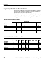
Table 1--45: 25 Hz and 50 Hz Frame and Field rates 1--42............
Table 1--46: 59.94 Hz, 23.98 Hz, and 29.97 Hz
Frame and Field rates 1--42..................................
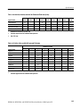
Table 1--47: 24 Hz, 30 Hz, and 60 Hz Frame and Field rates 1--43......
Table 1 -- 48: Supported Standards 1--44............................
Table 1--49: Common Alarms 1--45...............................
Table 1--50: HD Specific Alarms
(WFM7100, WFM7000 Op t. HD) 1--46.........................
Table 1 -- 51: SD Specific Alarms 1 -- 47.............................
Table 1--52: Composite Specific Alarms (Opt. CPS) 1--47.............
Table 1--53: Audio Alarms (Opts. DS an d AD Only) 1--47............
Table 1--54: Additional Audio Alarms (Opt. DDE Only) 1--48.........
Table 1--55: Additional Audio Alarms (Opt. DDE Only) 1--48.........
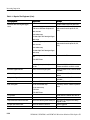
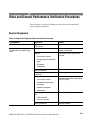
Table 2 -- 1: Required Test Equipment 2 --19.........................
Table 2--2: LCD Visual Defects 2--23..............................
Table 2--3: Diagnostics Limits 2--24...............................
Table 2 -- 4: Required Test Equipment
(V ideo and General Performance) 2--41........................
Table 2--5: Oscilloscope Settings for Serial Output Amplitude 2--66....
Table 2--6: Generator Characterization 2--84.......................
Table 2 -- 7: Required Test Equipment (Audio) 2--87..................

WFM6100, WFM7000, and WFM7100 Waveform Monitors With Option FP
v
General Safety Summary
Review the following safety precautions to avoid injury and prevent damage to
this product or any products connected to it. To avoid potential hazards, use this
product only as specified.
Only qualified personnel should perform service procedures.
Use Proper Power Cord. Use only the power cord specified for this product and
certified for the country of use.
Ground the Product. This product is grounded through the grounding conductor
of the power cord. To avoid electric shock, the grounding conductor must be
connected to earth ground. Before making connections to the input or output
terminals of the product, ensure that the product is properly grounded.
Observe All Terminal Ratings. To avoid fire or shock hazard, observe all ratings
and markings on the product. Consult the product manual for further ratings
information before making connections to the product.
Do not apply a potential to any terminal, including the common terminal, that
exceeds the maximum rating of that terminal.
Replace Batteries Properly. Replace batteries only with the proper type and rating
specified.
Do Not Operate Without Covers. Do not operate this product with covers or panels
removed.
Use Proper Fuse. Use only the fuse type and rating specified for this product.
Avoid Exposed Circuitry. Do not touch exposed connections and components
when power is present.
Do Not Operate With Suspected Failures. If you suspect there is damage to this
product, have it inspected by qualified service personnel.
Do Not Operate in Wet/Damp Conditions.
Do Not Operate in an Explosive Atmosphere.
Keep Product Surfaces Clean and Dry.
Provide Proper Ventilation. Refer to the manual’s installation instructions for
details on installing the product so it has proper ventilation.
ToAvoidFireor
Personal Injury

General Safety Summary
vi
WFM6100, WFM7000, and WFM7100 Waveform Monitors With Option FP
Terms in this Manual. These terms may appear in this manual:
WARNING. Warning statements identify conditions or practices that could result
in injury or loss of life.
CAUTION. Caution statements identify conditions or practices that could result in
damage to this product or other property.
Terms on the Product. These terms may appear on the product:
DANGER indicates an injury hazard immediately accessible as you read the
marking.
WARNING indicates an injury hazard not immediately accessible as you read the
marking.
CAUTION indicates a hazard to property including the product.
Symbols on t he Product. The following symbols may appear on the product:
CAUTION
Refer to Manual
Protective Ground
(Earth) Terminal
Symbols and Terms

WFM6100, WFM7000, and WFM7100 Waveform Monitors With Option FP
vii
Service Safety Summary
Only qualified personnel should perform service procedures. Read this Service
Safety Summary and the General Safety Summary before performing any service
procedures.
Do Not Service Alone. Do not perform internal service or adjustments of this
product unless another person capable of rendering first aid and resuscitation is
present.
Disconnect Power. To avoid electric shock, switch off the instrument power, then
disconnect the power cord from the mains power.
Use Care When Servicing With Power On. Dangerous voltages or currents may
exist in this product. Disconnect power, remove battery (if applicable), and
disconnect test leads before removing protective panels, soldering, or replacing
components.
To avoid electric shock, do not touch exposed connections.

Service Safety Summary
viii
WFM6100, WFM7000, and WFM7100 Waveform Monitors With Option FP

WFM6100, WFM7000, and WFM7100 Waveform Monitors With Option FP
ix
Environmental Considerations
This section provides information about the environmental impact of the
product.
Observe the following guidelines when recycling an instrument or component:
Equipment Recycling. Production of this equipment required the extraction and
use of natural resources. The equipment may contain substances that could be
harmful to the environment or human health if improperly handled at the
product’s end of life. In order to avoid release of such substances into the
environment and to reduce the use of natural resources, we encourage you to
recycle this product in an appropriate system that will ensure that most of the
materials are reused or recycled appropriately.
The symbol shown to the left indicates that this product
complies with the European Union’s requirements
according to Directive 2002/96/EC on waste electrical and
electronic equipment (WEEE). For information about
recycling options, check the Support/Service section of the
Tektronix Web site (www.tektronix.com).
Mercury Notification. This product uses an LC D backlight lamp that contains
mercury. Disposal may be regulated due to environmental considerations. Please
contact your local authorities or, within the United States, the Electronics
Industries Alliance (www. eiae.org) for disposal or recycling information.
This product has been classified as Monitoring and Control equipment, and is
outside the scope of the 2002/95/EC RoHS Directive. This product is known to
contain lead, cadmium, mercury, and hexavalent chromium.
Product End -of-Life
Handling
Restriction of H azardous
Substances

Environmental Considerations
x
WFM6100, WFM7000, and WFM7100 Waveform Monitors With Option FP

WFM6100, WFM7000, and WFM7100 Waveform Monitors With Option FP
xi
Preface
This reference document provides technical information about using the
WFM6100, WFM7000, and WFM7100 S eries multi-format waveform monitors
with Option FP installed.
Related User Documents
The following related user documents are available:
H WFM6100, WFM7000, and WFM7100 Waveform Monitors Release Notes
(Tektronix part number 071-2294-XX). This document describes any known
problems or behaviors that you might encounter while using the waveform
monitor.
H WFM6100, WFM7000, and WFM7100 Waveform Monitors Quick Start User
Manual (Tektronix part numbers: English, 071-2288-XX; Japanese
071-2289-XX; S implified Chinese, 071-22900-XX). This manual contains
the basic operating information for the instrument.
H WFM6100, WFM7000, and WFM7100 Waveform Monitors User Technical
Reference (Tektronix part number 071-2293-XX). This document contains
the detailed operating information for the instrument.
H WFM6100, WFM7000, and WFM7100 Waveform Monitors Service Manual
(Tektronix part number 071-2292-XX). This document provides servicing
information for the waveform monitor and is intended for qualified service
personnel only.

Preface
xii
WFM6100, WFM7000, and WFM7100 Waveform Monitors With Option FP
Related Reference Documents
The following related reference documents are available at the Tektronix, Inc.
Web site (www.tektronix.com):
H Preventing Illegal Colors. This application note describes how the Diamond,
Arrowhead, and Lightning displays can be used to help prevent the undesired
impact of color gamut violations and to simplify the assessment of proper
gamut compliance.
H Understanding Colors and Gamut. This poster provides a large visual
display of how the Diamond, Arrowhead, and Lightning displays can be
used to help prevent the undesired impact of color gamut violations.
H A Guide to Standard and High Definition Digital Video Measurements. This
book is a primer for understanding the basics for making standard and
high-definition, digital-video measurements.
H Analog and Digital Audio Monitoring. This application note describes how
to monitor analog and digital audio signals. Also discussed are specific
differences in the methods used to monitor analog audio versus digital audio,
and how to plan the transition from monitoring analog audio to monitoring
digital audio.
H Audio Monitoring. This application note describes balanced and unbalanced
audio signals, and explains the physical and electrical characteristics and the
specific strength and weaknesses of the different digital audio signal formats.
H Monitoring Surround Sound Audio. This application note describes the
basics of 5.1-channel surround sound audio and how to use the Surround
Sound display to visualize key audio-level and phase relationships in this
audio format.

Specifications


WFM6100, WFM7000, and WFM7100 Waveform Monitors With Option FP
1-1
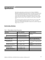
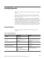
Specifications
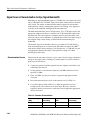
The following tables list the specifications for the Tektronix WFM6100,
WFM7000, and WFM7100 Waveform Monitors with Option FP installed. Items
listed in the Performance Requirement column are generally quantitative, and
can be tested by the Performance Verification procedure in Section 2 of this
manual. Items listed in the R eference Information column are useful operating
parameters that have typical values; information in this column is not guaran-
teed.
The specifications listed in the Electrical Specifications portion of these tables
apply over an ambient temperature range of +0 _Cto+40_C. The rated
accuracies are valid when the instrument is calibrated in an ambient temperature
range of +20 _Cto+30_C.
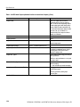
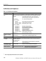
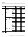
Electrical Specifications
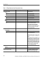
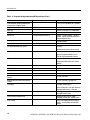
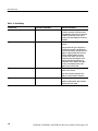
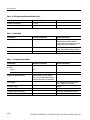
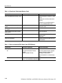
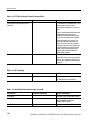
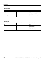
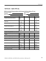
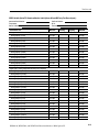
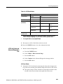
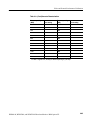
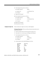
Table 1- 1: SDI Input Waveform Vert ical Characteristics
Characteristic Performance requirement Reference information
Vertical Measurement Accuracy Using graticule or cursor. Measure in
1X
0.5% of 700 mV full scale mode
g
g
YPbPr m ode.
5X
0.2% of 700 mV full scale mode
Gain X1, X2, X5, and X10
Variable Gain Range, Typical 0.25X to 1.8X, typical (variable gain
multiplied by fixed gain to get total gain).
Frequency Response -- HD
Luminance Channel (Y)
50 kHz to 30 MHz, 0.5%
50 kHz to 60 MHz for 1080P 60/59/50 dual
link formats.
Chrominance Channels (Pb, Pr)
50 kHz to 15 MHz, 0.5%
50 kHz to 30 MHz for 1080P 60/59/50 dual
link formats.
Frequency Response -- SD
Luminance Channel (Y)
50 kHz to 5.75 MHz, 0.5%
Chrominance Channels (Pb, Pr)
50 kHz to 2.75 MHz, 0.5%
YPbPr t o RGB Conversion Accuracy 0.1%, nominal

Specifications
1-2
WFM6100, WFM7000, and WFM7100 Waveform Monitors With Option FP
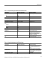
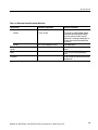
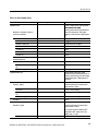
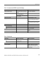
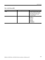
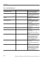
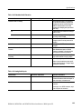
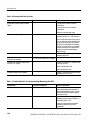
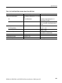
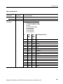
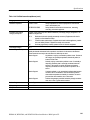
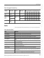
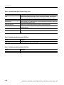
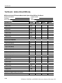
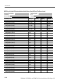
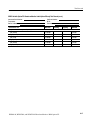
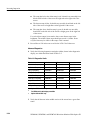
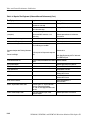
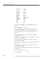
Table 1- 1: SDI Input Waveform Vert ical Characteristics (Cont.)
Characteristic Reference informationPerformance requirement
Step Response, Typical Sine-squared bars
Preshoot
SD
≤ 0.3% peak (2T5 bar)
HD
≤ 0.5% peak (2T30 bar)
Overshoot
SD
≤ 0.3% peak (2T5 bar)
HD
≤ 0.5% peak (2T30 bar)
Ringing
SD
≤ 0.8% peak-peak (2T5 bar)
HD
≤ 0.8% peak-peak (2T30 bar)
Most of the error seen on the display
comes from the inherent ringing in the
digital data. The response of the monitor is
close to the theoretical limit of a perfect
sinx/x reconstruction filter.
Pulse Response, Typical Blackman pul se
Baseline Ringing
SD
≤0.6% peak-peak (2T5)
HD
≤0.7% peak-peak (2T30)
Pulse-to-bar ratio 0.995:1 to 1.005:1 on ap-
propriate Sine Squared or Blackman 2T
pulse.
A sine-squared pulse near Nyquist is not
band-limited and so inherently has ringi ng
much larger than the waveform monitor filter.
A three term Blackman pulse with the same
HAD has much less inherent ringing, so it is
a bet ter choice for most testing. See Digital
to Analog Conversion, Data and Filter Re-
quirements, SMPTE Journal Mar 1995,
Vol. 104, Fibush, Baker, Penny.
Tilt, Typical
Field Rat e 0.1%
Line Rate 0.1%
Off Screen Recovery, Typical 0.1% variation in baseline of a 5 MHz
modulated pulse when positioned any-
where on screen at any gain setting.
Page is loading ...
Page is loading ...
Page is loading ...
Page is loading ...
Page is loading ...
Page is loading ...
Page is loading ...
Page is loading ...
Page is loading ...
Page is loading ...
Page is loading ...
Page is loading ...
Page is loading ...
Page is loading ...
Page is loading ...
Page is loading ...
Page is loading ...
Page is loading ...
Page is loading ...
Page is loading ...
Page is loading ...
Page is loading ...
Page is loading ...
Page is loading ...
Page is loading ...
Page is loading ...
Page is loading ...
Page is loading ...
Page is loading ...
Page is loading ...
Page is loading ...
Page is loading ...
Page is loading ...
Page is loading ...
Page is loading ...
Page is loading ...
Page is loading ...
Page is loading ...
Page is loading ...
Page is loading ...
Page is loading ...
Page is loading ...
Page is loading ...
Page is loading ...
Page is loading ...
Page is loading ...
Page is loading ...
Page is loading ...
Page is loading ...
Page is loading ...
Page is loading ...
Page is loading ...
Page is loading ...
Page is loading ...
Page is loading ...
Page is loading ...
Page is loading ...
Page is loading ...
Page is loading ...
Page is loading ...
Page is loading ...
Page is loading ...
Page is loading ...
Page is loading ...
Page is loading ...
Page is loading ...
Page is loading ...
Page is loading ...
Page is loading ...
Page is loading ...
Page is loading ...
Page is loading ...
Page is loading ...
Page is loading ...
Page is loading ...
Page is loading ...
Page is loading ...
Page is loading ...
Page is loading ...
Page is loading ...
Page is loading ...
Page is loading ...
Page is loading ...
Page is loading ...
Page is loading ...
Page is loading ...
Page is loading ...
Page is loading ...
Page is loading ...
Page is loading ...
Page is loading ...
Page is loading ...
Page is loading ...
Page is loading ...
Page is loading ...
Page is loading ...
Page is loading ...
Page is loading ...
Page is loading ...
Page is loading ...
Page is loading ...
Page is loading ...
Page is loading ...
Page is loading ...
Page is loading ...
Page is loading ...
Page is loading ...
Page is loading ...
Page is loading ...
Page is loading ...
Page is loading ...
Page is loading ...
Page is loading ...
Page is loading ...
Page is loading ...
Page is loading ...
Page is loading ...
Page is loading ...
Page is loading ...
Page is loading ...
Page is loading ...
Page is loading ...
Page is loading ...
Page is loading ...
Page is loading ...
Page is loading ...
Page is loading ...
Page is loading ...
Page is loading ...
Page is loading ...
Page is loading ...
Page is loading ...
Page is loading ...
Page is loading ...
Page is loading ...
Page is loading ...
Page is loading ...
Page is loading ...
Page is loading ...
Page is loading ...
Page is loading ...
Page is loading ...
Page is loading ...
Page is loading ...
Page is loading ...
Page is loading ...
Page is loading ...
Page is loading ...
Page is loading ...
Page is loading ...
Page is loading ...
Page is loading ...
Page is loading ...
Page is loading ...
-
 1
1
-
 2
2
-
 3
3
-
 4
4
-
 5
5
-
 6
6
-
 7
7
-
 8
8
-
 9
9
-
 10
10
-
 11
11
-
 12
12
-
 13
13
-
 14
14
-
 15
15
-
 16
16
-
 17
17
-
 18
18
-
 19
19
-
 20
20
-
 21
21
-
 22
22
-
 23
23
-
 24
24
-
 25
25
-
 26
26
-
 27
27
-
 28
28
-
 29
29
-
 30
30
-
 31
31
-
 32
32
-
 33
33
-
 34
34
-
 35
35
-
 36
36
-
 37
37
-
 38
38
-
 39
39
-
 40
40
-
 41
41
-
 42
42
-
 43
43
-
 44
44
-
 45
45
-
 46
46
-
 47
47
-
 48
48
-
 49
49
-
 50
50
-
 51
51
-
 52
52
-
 53
53
-
 54
54
-
 55
55
-
 56
56
-
 57
57
-
 58
58
-
 59
59
-
 60
60
-
 61
61
-
 62
62
-
 63
63
-
 64
64
-
 65
65
-
 66
66
-
 67
67
-
 68
68
-
 69
69
-
 70
70
-
 71
71
-
 72
72
-
 73
73
-
 74
74
-
 75
75
-
 76
76
-
 77
77
-
 78
78
-
 79
79
-
 80
80
-
 81
81
-
 82
82
-
 83
83
-
 84
84
-
 85
85
-
 86
86
-
 87
87
-
 88
88
-
 89
89
-
 90
90
-
 91
91
-
 92
92
-
 93
93
-
 94
94
-
 95
95
-
 96
96
-
 97
97
-
 98
98
-
 99
99
-
 100
100
-
 101
101
-
 102
102
-
 103
103
-
 104
104
-
 105
105
-
 106
106
-
 107
107
-
 108
108
-
 109
109
-
 110
110
-
 111
111
-
 112
112
-
 113
113
-
 114
114
-
 115
115
-
 116
116
-
 117
117
-
 118
118
-
 119
119
-
 120
120
-
 121
121
-
 122
122
-
 123
123
-
 124
124
-
 125
125
-
 126
126
-
 127
127
-
 128
128
-
 129
129
-
 130
130
-
 131
131
-
 132
132
-
 133
133
-
 134
134
-
 135
135
-
 136
136
-
 137
137
-
 138
138
-
 139
139
-
 140
140
-
 141
141
-
 142
142
-
 143
143
-
 144
144
-
 145
145
-
 146
146
-
 147
147
-
 148
148
-
 149
149
-
 150
150
-
 151
151
-
 152
152
-
 153
153
-
 154
154
-
 155
155
-
 156
156
-
 157
157
-
 158
158
-
 159
159
-
 160
160
-
 161
161
-
 162
162
-
 163
163
-
 164
164
-
 165
165
-
 166
166
-
 167
167
-
 168
168
-
 169
169
-
 170
170
-
 171
171
-
 172
172
-
 173
173
-
 174
174


Tektronix WFM6100 Opt. MB Technical Reference
- Type
- Technical Reference
- This manual is also suitable for
Ask a question and I''ll find the answer in the document
Finding information in a document is now easier with AI
Related papers
-
Tektronix WFM7000 Opt. MB Quick Start User Manual
-
-
-
-
-
-
-
-
-
Other documents
-
 Analog Arts SG884 User manual
-
 ADS Technologies API-558-EFS Supplementary Manual
-
Sony LMD-1420MD User manual
-
NEO Bridge X_NEO User manual
-
GE X-ray Accessories Quick start guide
-
Furman Sound MS2A-1 User manual
-
-
 Whirlwind AESDA User manual
-
Barco DCS-200 Quick start guide
-
SRS SR2124 Owner's manual


