Badger Meter 2000 User manual

Type
User manual
RTS-UM-00380-EN-09 (January 2015)
User Manual
Recordall® Turbo Series Meters
Models 160 (1-1/2"), 200 (2"), 450 (3"), 1000 (4"), 2000 (6"),
3500 (8"), 5500 (10"), 6200 (12"), 6600 (16") & 10000 (20")
Recordall® Turbo Series Meters
RTS-UM-00380-EN-09Page ii January 2015
CONTENTS
Scope of this Manual . . . . . . . . . . . . . . . . . . . . . . . . . . . . . . . . . . . . . . . . . . . . . . . . . . . . . . . . . . . . . . . . . . . . 5
Product Information . . . . . . . . . . . . . . . . . . . . . . . . . . . . . . . . . . . . . . . . . . . . . . . . . . . . . . . . . . . . . . . . . . . . 5
Product Description . . . . . . . . . . . . . . . . . . . . . . . . . . . . . . . . . . . . . . . . . . . . . . . . . . . . . . . . . . . . . . . . . .5
Accessories . . . . . . . . . . . . . . . . . . . . . . . . . . . . . . . . . . . . . . . . . . . . . . . . . . . . . . . . . . . . . . . . . . . . . . . 5
Related Literature . . . . . . . . . . . . . . . . . . . . . . . . . . . . . . . . . . . . . . . . . . . . . . . . . . . . . . . . . . . . . . . . . . . 5
Safety Information . . . . . . . . . . . . . . . . . . . . . . . . . . . . . . . . . . . . . . . . . . . . . . . . . . . . . . . . . . . . . . . . . . .6
Unpacking and Inspection. . . . . . . . . . . . . . . . . . . . . . . . . . . . . . . . . . . . . . . . . . . . . . . . . . . . . . . . . . . . . .6
Installation. . . . . . . . . . . . . . . . . . . . . . . . . . . . . . . . . . . . . . . . . . . . . . . . . . . . . . . . . . . . . . . . . . . . . . . . . . .7
Preinstallation Considerations . . . . . . . . . . . . . . . . . . . . . . . . . . . . . . . . . . . . . . . . . . . . . . . . . . . . . . . . . . . 7
Installing the Meter . . . . . . . . . . . . . . . . . . . . . . . . . . . . . . . . . . . . . . . . . . . . . . . . . . . . . . . . . . . . . . . . . .8
Maintenance . . . . . . . . . . . . . . . . . . . . . . . . . . . . . . . . . . . . . . . . . . . . . . . . . . . . . . . . . . . . . . . . . . . . . . . . . 9
Maintenance Equipment. . . . . . . . . . . . . . . . . . . . . . . . . . . . . . . . . . . . . . . . . . . . . . . . . . . . . . . . . . . . . . .9
Preventive Maintenance . . . . . . . . . . . . . . . . . . . . . . . . . . . . . . . . . . . . . . . . . . . . . . . . . . . . . . . . . . . . . . . 9
Periodic Inspection . . . . . . . . . . . . . . . . . . . . . . . . . . . . . . . . . . . . . . . . . . . . . . . . . . . . . . . . . . . . . . . 9
Cleaning. . . . . . . . . . . . . . . . . . . . . . . . . . . . . . . . . . . . . . . . . . . . . . . . . . . . . . . . . . . . . . . . . . . . . . 9
Shutdown Instructions . . . . . . . . . . . . . . . . . . . . . . . . . . . . . . . . . . . . . . . . . . . . . . . . . . . . . . . . . . . . . . . . 9
Calibration Check and Adjustment . . . . . . . . . . . . . . . . . . . . . . . . . . . . . . . . . . . . . . . . . . . . . . . . . . . . . . . 10
Accuracy Test. . . . . . . . . . . . . . . . . . . . . . . . . . . . . . . . . . . . . . . . . . . . . . . . . . . . . . . . . . . . . . . . . . .10
Calibration . . . . . . . . . . . . . . . . . . . . . . . . . . . . . . . . . . . . . . . . . . . . . . . . . . . . . . . . . . . . . . . . . . . .11
Servicing Parts and Assemblies. . . . . . . . . . . . . . . . . . . . . . . . . . . . . . . . . . . . . . . . . . . . . . . . . . . . . . . . . . . . .12
Removing the Meter Head. . . . . . . . . . . . . . . . . . . . . . . . . . . . . . . . . . . . . . . . . . . . . . . . . . . . . . . . . . . . .12
Removing the Local Register or Encoder . . . . . . . . . . . . . . . . . . . . . . . . . . . . . . . . . . . . . . . . . . . . . . . . . . . .12
Removing the Measuring Element . . . . . . . . . . . . . . . . . . . . . . . . . . . . . . . . . . . . . . . . . . . . . . . . . . . . .13
Removing the Magnet Carrier . . . . . . . . . . . . . . . . . . . . . . . . . . . . . . . . . . . . . . . . . . . . . . . . . . . . . . . .13
Removing the Straightening Vanes/Nose Cone . . . . . . . . . . . . . . . . . . . . . . . . . . . . . . . . . . . . . . . . . . . . .13
Removing the Calibration Mechanism. . . . . . . . . . . . . . . . . . . . . . . . . . . . . . . . . . . . . . . . . . . . . . . . . . .14
Inspecting the Rotor and Bearings . . . . . . . . . . . . . . . . . . . . . . . . . . . . . . . . . . . . . . . . . . . . . . . . . . . . .15
Reinstalling the Turbo Meter Head Assembly . . . . . . . . . . . . . . . . . . . . . . . . . . . . . . . . . . . . . . . . . . . . . .17
Placing the Meter Back in Service . . . . . . . . . . . . . . . . . . . . . . . . . . . . . . . . . . . . . . . . . . . . . . . . . . . . . . . . 17
Specications . . . . . . . . . . . . . . . . . . . . . . . . . . . . . . . . . . . . . . . . . . . . . . . . . . . . . . . . . . . . . . . . . . . . . . . .18
1-1/2" to 12" Meters . . . . . . . . . . . . . . . . . . . . . . . . . . . . . . . . . . . . . . . . . . . . . . . . . . . . . . . . . . . . . . . . . 18
Materials . . . . . . . . . . . . . . . . . . . . . . . . . . . . . . . . . . . . . . . . . . . . . . . . . . . . . . . . . . . . . . . . . . . . .18
16" and 20" Meters. . . . . . . . . . . . . . . . . . . . . . . . . . . . . . . . . . . . . . . . . . . . . . . . . . . . . . . . . . . . . . . . . .19
Materials . . . . . . . . . . . . . . . . . . . . . . . . . . . . . . . . . . . . . . . . . . . . . . . . . . . . . . . . . . . . . . . . . . . . .19
User Manual
RTS-UM-00380-EN-09 Page iii January 2015
Recordall® Turbo Series Meters
RTS-UM-00380-EN-09Page iv January 2015
SCOPE OF THIS MANUAL
This manual contains installation, operation and maintenance procedures for the Badger
Meter® Recordall® Turbo Series
meters with magnetic drives. To ensure efficient operation of the meters, read and understand the instructions in this manual.
Retain the manual in a location where it is readily available.
PRODUCT INFORMATION
Product Description
The Recordall
Turbo Series meters use proven design features such as thrust-compensated rotor geometry, direct drive
magnetic coupling, and dual outboard rotor bearings to achieve high accuracy over a broad flow range. Extended product
service life is achieved at higher levels of accuracy, in addition to lower meter maintenance costs. The Turbo meters are
available in 1-1/2", 2", 3", 4", 6", 8", 10", 12", 16" and 20" sizes.
Incorporating unitized construction with corrosion-resistant assemblies, the basic components of the Recordall Turbo Series
consist of the housing and the completely removable measuring element. The meter housing and cover plate are lead-free
bronze (1-1/2" to 10" sizes). The 12" to 20" meter housings are cast iron with a heat fused epoxy coating. The measuring
element is constructed of high-impact strength thermoplastics. Recordall Turbo Series meters are also equipped with an
integral calibration mechanism for in-line accuracy calibration.
In the operation of a turbo meter, water flows through the straightening vanes and a nose cone at the inlet side of the meter
so that the swirling effect of upstream piping is minimized. The water then strikes the rotor blades, causing the rotor to turn. A
downstream nose cone includes straightening vanes to limit the downstream effects of flow profile distortions. Optional NPT
test ports are provided for field performance testing.
Motion of the rotor is transferred by means of a worm drive to a vertical shaft driving a gear set, which transmits the rotation
to the meter's registration device. The direct drive magnetic coupling provides accurate flow registration during line surges,
and allows the permanently sealed register to be easily removed to facilitate in-line service.
Accessories
Meters and encoders are compatible with Badger Meter AMR/AMI meter reading systems and other approved reading
technologies. AMR/AMI solutions are available for all Recordall Turbo Series meters. All reading options can be removed from
the meter without disrupting water service. Badger Meter encoders provide years of reliable, accurate readings for a variety of
applications and are also available pre-wired to Badger Meter approved AMR/AMI solutions. See details at
www.badgermeter.com.
A strainer is recommended to provide optimal flow conditioning and protection for the measuring element. An integral
strainer is available as an option for 1-1/2" through 4" meter sizes. The stainless steel strainer is built into the inlet end
and includes a removable cover plate to permit easy access for routine cleaning. External strainers are available in sizes 2"
through 12".
Related Literature
The Recordall Turbo Series Meters Product Data Sheet contains information on operating principle, meter construction,
materials, tolerances and specifications.
The Recordall Turbo Series Meters Parts List contains illustrations of parts, part numbers, and part descriptions.
Scope of this Manual
RTS-UM-00380-EN-09 Page 5 January 2015
Safety Information
The installation of the Recordall Turbo Series meter must comply with all applicable federal, state, and local rules, regulations,
and codes.
Failure to read and follow these instructions can lead to misapplication or misuse of the meter, resulting in personal injury and
damage to equipment.
Unpacking and Inspection
To avoid damage in transit, Badger Meter Recordall Turbo Series meters are shipped to the customer in special shipping
containers. Upon receipt of shipment, be sure to follow these unpacking and inspection procedures:
OTE:N If damage to a shipping container is evident upon receipt of a meter, request that a representative of the carrier be
present when the meter is unpacked.
a. Carefully open the shipping container, following any instructions that may be marked on the container. Remove all
cushioning material surrounding the meter and carefully lift the meter from the container. Keep the container and
all packing material for possible use in reshipment or storage.
b. Visually inspect the meter and applicable accessory devices for any signs of damage such as scratches, loose or
broken parts or other physical damage that may have occurred during shipment.
OTE:N If damage is found, request an inspection by carrier’s agent within 48 hours of delivery. Then file a claim with the
carrier. A claim for equipment damaged in transit is the responsibility of the customer.
Product Information
RTS-UM-00380-EN-09Page 6 January 2015
INSTALLATION
Procedures for installing Recordall Turbo Series meters are essentially the same for all meter sizes. Any special instructions
required for the installation or connection of accessory devices such as AMR/AMI technologies or strainers is provided in the
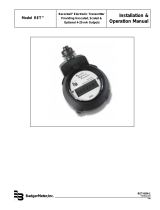
literature for those devices. Figure 1 shows a recommended meter installation.
BADGER PLATE
STRAINER AND TURBO
SERIES METERS
COUPLING
ADAPTOR
SERVICE
SADDLE
SHUT-OFF
VALVE
TEST TEE
MINIMUM TWO
PIPE DIAMETERS
DOWNSTREAM
OF TURBO
METER
MINIMUM OF FIVE
DIAMETERS OF
STRAIGHT PIPE
VALVE
(open)
BY-PASS
(PERMANENT OR
TEMPORARY)
UPSTREA
M
DOWNSTREA
M
Figure 1: Recommended meter installation
Preinstallation Considerations
Before proceeding any further with the installation, rst read the instructions in the paragraphs immediately following to
become familiar with the requirements and procedures involved.
OTE:N The Recordall Turbo Series meters are designed for operation in HORIZONTAL piping arrangements.
Be sure that the meter flow range and size of the meter coincide with the intended service and demand for water.
THE LIFE OF THE TURBO METER WILL BE CURTAILED IF OPERATED AT FLOW RATES HIGHER THAN SPECIFIED.
The meters are designed for use in cold water service (up to 120° F or 49° C) within the applicable flow requirements
for Turbo meters. For use with water at higher temperatures, consult your Badger Meter representative or nearest
Badger Meter regional sales office.
If solid material is present in the water to be metered, a strainer must be installed in the service piping upstream of the
meter. The strainer, in addition to protecting the meter from debris in the line, minimizes the effect of velocity profile
distortions or turbulence caused by changes in pipe direction or valving resulting in more accurate registration.
Avoid locating the meter in close quarters. Allow sufficient space to permit access for meter reading, testing,
and maintenance.
Because of the need to test large meters periodically to verify their performance, it is recommended that a bypass system
be incorporated into the piping arrangement. This will also provide a means of performing periodic cleanout and routine
maintenance without interrupting service to the customer. A test port is incorporated in the meter housing and can be
used for field accuracy testing.
The Recordall Turbo Series meter is accuracy and pressure tested prior to shipment, therefore no field adjustments
are required. As turbine performance is directly related to the flow conditions of the water stream entering the meter,
upstream fittings and piping changes can adversely affect flow registration. For valid registration and proper performance,
consider the following installation considerations:
When installing the meter with a separate plate strainer or integral strainer, a minimum of 5 pipe diameters of straight,
unobstructed pipe is recommended upstream of the meter. For optimum protection and accuracy, this straight
pipe spool piece should be installed between the separate strainer and meter (see Figure 1). A minimum of 10 pipe
diameters (minimum of 25 pipe diameters for smallest size) of straight unobstructed pipe is recommended upstream
of a meter installed without a plate strainer. The deletion of a strainer, however, is not recommended. This allows for
dampening of velocity profile distortions caused by elbows, pumps, and dirt traps upstream of the meter. Where spiral
flows are created by three dimensional elbows or rotary pumps, additional distance to dampen the effect is beneficial.
If a basket or Y-type strainer is used, place it 5 to 10 pipe diameters upstream of the meter to dampen velocity profile
distortions created by this design.
Installation
RTS-UM-00380-EN-09 Page 7 January 2015
Do not install check valves or pressure reducing devices upstream of the meter.
Valves immediately upstream of the meter should only be fully-open gate valves. Butterfly valves are acceptable if they
are 5 pipe diameters or more upstream from the meter. Downstream, fully open gate or butterfly valves can be used.
The service saddle (or reducing tee), which is used for field accuracy testing, should be at least 2 pipe diameters
downstream of the meter's outlet flange.
Unweighted check valves should not be located closer than 3 pipe diameters downstream of the meter.
Externally weighted check valves and pressure reducing devices should not be located closer than 5 pipe diameters of
the meter.
When installing a Turbo meter and plate strainer of a size smaller than the pipe installation, to reduce the effect of
jetting caused by the increase in flow velocity, a minimum of 5 pipe diameters of pipe equal in size to the meter, is
required upstream of the meter. Additional length is required if a sharp contraction or an eccentric reducer, rather than
a concentric, tapered reducer is used.
Installing the Meter
Overall dimensions and laying lengths of each meter size are listed in the Recordall Turbo Series Meter Product Data Sheet.
Review the dimensional requirements, choose an installation point in the piping, and proceed as follows:
1. Measure precisely the overall length of the meter with gaskets attached to the inlet and outlet ange connections.
2. Provide proper gap length in service piping.
3. Install meter in the pipeline so that the ow arrow on the meter housing points in the same direction as water ow.
4. With meter and gaskets in place, tighten ange connection bolts.
5. To relieve possible strain on the piping, position a meter support under the meter housing where appropriate.
TURBINE METERS MUST OPERATE IN A COMPLETELY FILLED LINE AT ALL TIMES. THE DOWNSTREAM PIPING MUST
ALWAYS BE ARRANGED TO PROVIDE SUFFICIENT BACK PRESSURE TO MAINTAIN A FULL LINE AT THE METER. BY
ELIMINATING AIR IN THE LINE, AS WELL AS SUDDEN FLOW SURGES, INACCURATE REGISTRATION AND DAMAGE TO THE
TURBINE MECHANISM CAN BE AVOIDED.
Performance Checks
Any valves or devices controlling the flow of water through a Turbo meter must always be opened and closed SLOWLY to
prevent shock loads that may damage the meter’s rotor assembly.
Complete the following checks to ensure that a Turbo meter is properly installed and operational:
Slowly open the upstream valve to apply water pressure to the meter and check for leaks. Tighten the flange bolts as
required.
Perform a functional test of the meter. Slowly open valve on downstream side of the meter to evacuate any air that may
have been trapped in the service line. When air has been eliminated, increase demand flow rate by further opening the
downstream valve or valves. Observe the register for correct direction of flow. Continue to open the demand side valves
to a flow rate sufficient to open the valve assembly in the meter—a procedure which will start water flowing through the
turbo high-side rotor. The high flow pointer will now move in the proper direction. Now open all applicable service valves.
Check the flow rate to verify that the flow does not exceed the maximum continuous duty specification. The rate of flow
can be quickly checked by timing the quantity registered through the meter in one minute.
Installation
RTS-UM-00380-EN-09Page 8 January 2015
MAINTENANCE
This section is limited to information pertaining to the general maintenance of Badger
Meter Recordall Turbo Series meters.
An exploded view of the meter, along with part numbers and descriptions, are provided in the Recordall Turbo Series Meters
Parts List.
Maintenance Equipment
The tools and equipment recommended for use in servicing and maintaining of Recordall Turbo Series meters consist of the
usual complement of hand tools used by plumbers and mechanics.
Preventive Maintenance
The purpose of preventive maintenance is to ensure efficient operation and long life of the meter by detecting and correcting
any defect that might damage the meter or cause it to fail. Preventive maintenance consists of periodic inspection, accuracy
testing, and cleaning procedures.
Periodic Inspection
Visually inspect the meter for missing hardware, loose screws, broken or scratched register lenses or any other signs of
wear or deterioration.
Verify that the meter is operating at the proper flow rate and pressure. A loss in pressure, coupled with a decrease in flow
rate, may indicate that the screen in the upstream pipeline—or the meter itself—is clogged with foreign material and
needs cleaning.
Cleaning
Clean all dirt, grease, moisture or other foreign material from the exterior of the meter. After cleaning, rinse thoroughly
with water.
In the event that system pressure has been reduced and the upstream filter or meter is clogged, the foreign material
must be flushed out. To flush the screen, open the cleanout plug and purge the foreign material with fresh water from the
service line. If cleaning the screen does not restore system pressure, the Turbo meter also should be flushed by purging
with fresh service water through the cleanout plugs located on the housing.
Integral Strainer Units: Before attempting service/maintenance of strainer section, system pressure must be removed. After
system pressure is removed, remove cover bolts and cover. Clean out/flush strainer section of all loose particles/debris.
After cleaning is complete, reinstall screen and reassemble. Return meter to normal service.
Shutdown Instructions
If the turbo meter is to be shut down for an extended period of time or if it is being removed from service, Badger Meter
recommends that the meter and measuring components be thoroughly flushed to prevent the settling out of undissolved
solids or the accumulation of corrosive deposits. If there is an upstream strainer in the line, it also should be flushed at
this time.
Maintenance
RTS-UM-00380-EN-09 Page 9 January 2015
Calibration Check and Adjustment
The accuracy of the Recordall Turbo Series meters is tested at the factory before shipment. However, after a long period of
service, it may be necessary to recalibrate a meter. The meter can be tested for accuracy using appropriate connections with
either a test tank of known volume or a test meter. The meter can be tested in the setting by running output flow through
the optional test port, if so equipped. The Recordall Turbo Series integral calibration mechanism can be adjusted under
line pressure, simplifying and reducing calibration time. The following instructions are provided to assist in performing a
calibration check and adjustment.
Accuracy Test
IF THE OPTIONAL TEST PORT IS TO BE USED, UPSTREAM AND DOWNSTREAM VALVES MUST BE CLOSED PRIOR TO
REMOVING PLUG AND INSTALLING APPROPRIATE CONNECTIONS. FAILURE TO DO SO CAN LEAD TO PLUG BEING
EJECTED FROM HOUSING, CAUSING PERSONAL INJURY AND/OR PROPERTY DAMAGE. WHEREVER AN INSTALLATION
IS EQUIPPED WITH A DRAIN VALVE FOR METER FLUSHING, OPEN THE DRAIN VALVE TO RELIEVE PRESSURE WITHIN
THE METER. IF THE INSTALLATION DOES NOT HAVE A DRAIN VALVE, CAREFULLY LOOSEN TEST PLUG UNTIL IT BEGINS
LEAKING. STOP AND WAIT FOR PRESSURE TO BLEED DOWN, THEN CONTINUE TO SLOWLY LOOSEN, MAKING CERTAIN
THE PRESSURE IS COMPLETELY BLED OFF BEFORE REMOVING.
1. After installing the appropriate connections, test the meter by closing the downstream valve (if using integral test
port) and slowly opening the upstream valve. Slowly open the test circuit downstream valve to throttle ow for
test purposes.
2. Place a test tank of known volume at the output of the meter. An alternative is to connect a calibrated test meter to the
output. Accuracy testing requires test volumes at least as large as the register test circle.
3. As in testing the accuracy of any meter, the Recordall Turbo Series meter must rst be purged of air by running water
through the meter.
OTE:N Good test practices, such as those outlined in the AWWA M6 manual, are required to perform reliable field accuracy
tests. Register "jump" can occur in some instances if valves are abruptly opened or closed. While this jump is
not accumulative (no affects in service billing), it can affect accuracy results (1% per division on a one test circle
volumetric test).
4. Operate the meter until the test tank is lled to the calibrated level or the predetermined quantity has registered on
the calibrated test meter. Because accuracy may vary slightly with ow rate, it is recommended that the meter be
tested at low, intermediate and high ows.
5. Record the quantity registered on the meter during the test.
6. Perform the following calculations to determine meter accuracy:
(Quantity Registered on Meter)/(Test Tank or Test Meter Quantity) x 100=Meter Accuracy
Maintenance
RTS-UM-00380-EN-09Page 10 January 2015
Calibration
The meter's calibration ring is preset and sealed at the factory. In normal service, it should not have to be reset. If a retest is
required in which a calibrated test stand reveals that the meter needs recalibration, proceed as follows (see Figure 2):
The total range of the calibration adjustment is about 10%. Tested and calibrated at the factory, the calibration mechanism
will allow for a ± 5% adjustment in the field. Due to the floating rotor design principle, the calibration mechanism contains
some clearance for proper part fit resulting in some hysteresis or "deadband" when changing directions with calibration shaft.
Adjustments should be made in small increments in one direction to avoid need for counter rotation. If desired setting is
exceeded, counter rotations in small increments should be made, even though first reverse setting may result in no apparent
change. This is normal, and subsequent changes will cause reverse accuracy curve shift.
Figure 2: Calibrating turbo meter, shown with optional test plug
1. Remove the calibration shaft seal plug by puncturing the plug in the slot provided and twisting or prying the plug
from the hole.
2. Loosen the calibration shaft lock screw.
3. Adjust the calibration ring with a screwdriver as follows:
To increase the registration, turn the calibration shaft clockwise. This speeds up the rotor, increasing registration.
To decrease the registration, turn the calibration shaft counterclockwise. This slows down the rotor,
decreasing registration.
4. With the calibration shaft turned to the desired setting, tighten the lock screw while maintaining the calibration
shaft position.
5. Retest the meter to conrm the accuracy of the calibration setting. If the meter is still out of calibration, repeat
the procedure.
6. Replace the calibration shaft seal plug with a new one.
Maintenance
RTS-UM-00380-EN-09 Page 11 January 2015
SERVICING PARTS AND ASSEMBLIES
When the performance of a Turbo meter indicates a need for
servicing, refer to the following instructions pertaining to removal,
inspection and installation of service parts and assemblies. Also
see the Recordall Turbo Series Meter Parts List for part numbers
of replaceable components and correct ordering information. If
satisfactory repair cannot be made, contact Badger Meter.
Removing the Meter Head
Recordall Turbo Series meters can be serviced without removing
them from the line. A typical installation would be equipped with
drain and piping valves. To inspect or replace components of
the head assembly, close the upstream and downstream valves.
However, if the installation does not have a drain valve, proceed
as follows to relieve pressure:
UPSTREAM AND DOWNSTREAM VALVES MUST BE CLOSED
BEFORE ATTEMPTING TO REMOVE METER HEAD FROM
HOUSING. FAILURE TO DO SO CAN LEAD TO THE HEAD BEING
"EJECTED" FROM HOUSING, CAUSING PERSONAL INJURY
AND/OR PROPERTY DAMAGE!
1. Loosen each of the head bolts about 1-1/2 turns. Do not
completely remove the bolts.
2. If the O-ring between the meter head and the housing
is secure and not leaking, pry the measuring element
assembly loose by inserting a screwdriver blade where the
head and housing join together.
BE SURE THAT ANY WATER COMING OUT OF THE METER HEAD
DOES NOT SPRAY ONTO ELECTRICAL EQUIPMENT AND CREATE
A SHOCK HAZARD.
3. Allow the meter to drain and relieve internal pressure.
4. When pressure is relieved, remove the head bolts. Lift the
measuring element assembly from the housing.
Removing the Local Register or Encoder
The Recordall Turbo Series meter registers and encoders are easily
removable to facilitate in-line service.
1. Remove the register lid and shroud by removing the seal
screw.
2. Remove the shroud by rotating the register assembly
counterclockwise until it stops. This provides clearance so
it can be lifted o the measuring element assembly. See
Figure 3 and Figure 4.
To reinstall the register, follow the above procedure in
reverse order.
Figure 3: Removing the meter head assembly, 1-1/2" to 4" meters
Figure 4: Removing the meter head assembly, 6" meters
Servicing Parts and Assemblies
RTS-UM-00380-EN-09Page 12 January 2015
Removing the Measuring Element
OTE:N A cage seal is installed in the 1-1/2" to 6" Recordall
®
Turbo Series so that the entire water volume flows through the
measuring element.
1. Remove the O-ring and cage seal.
2. Check for damage and clean or replace prior to reassembly.
3. To remove the measuring element from the cover, remove the calibration shaft seal plug and the lock screw.
See Figure 3 and Figure 4.
4. Place the cover register-side down on a table or flat surface.
5. Lightly tap or press the calibration shaft from the wet side out of the bore in the cover (1-1/2" to 4" only). Do not strike
or bend the calibration linkage.
6. The measuring element insert can be removed from the cover plate for service or replacement by removing the cage
set screws (quantity of one for 1/-1/2" to 4", quantity of 4 for the 6" size). See Figure 3 and Figure 4.
7. Holding the cover plate in one hand, rotate the thermoplastic element counter-clockwise until the bayonet-like tabs
are aligned with open areas of the cover plate (1-1/2" to 4" only).
8. Remove the element from the cover plate.
Removing the Magnet Carrier
1. To remove the magnet carrier from the measuring element insert, lift it o the stainless steel pin. See Figure 3 and
Figure 4.
2. Check the condition of the magnet and gear on the magnet carrier for damage or wear. If signicant wear or damage is
present, replace the magnet carrier.
3. Remove the hold-down strap. See Figure 3 and Figure 4.
4. Check the condition of the transmission shaft gear for damage or wear. If signicant wear or damage is present, replace
the gear.
5. Lift the gear o the shaft.
Removing the Straightening Vanes/Nose Cone
The straightening vanes are an integral part of the upstream and downstream nose cone assemblies. See Figure 3 and Figure 4.
To gain access to them, remove the measuring element from the cover.
Removing the upstream nose cone provides access to the rotor, calibration ring and the transmission assembly.
Removing the upstream nose cone
1. Unscrew the upstream nose cone setscrew. For 1-1/2" to 4" meters, slide the calibration linkage into the cage insert
stop.
2. Take hold of the nose cone/straightening vanes and turn them clockwise, thereby disengaging the calibration linkage
from the tab on the calibration ring and unlocking the bayonets of the nose cones from the cage (see Figure 5).
3. If the tab of the calibration ring has not disengaged the linkage, rotate the ring carefully by pushing the struts at the
interior of the element (between the straightening vanes and the rotor). Pull the nose cone assembly out from the
measuring element insert. For 6" meters, remove the transmission gear by lifting it o the shaft, noting the alignment
of the D-shaped bore with the at on the shaft (required to align for assembly).
4. Remove the retaining ring that holds down the calibration drive plate, located under magnet carrier magnet. See
Figure 4 and Figure 6. Remove drive plate. Rotate calibration ring until pin clears slot of cage. Take hold of the nose
cone/straightening vanes and turn clockwise. Pull the nose cone assembly out from the measuring element insert.
Remove rotor assembly.
Servicing Parts and Assemblies
RTS-UM-00380-EN-09 Page 13 January 2015
Removing the rear nose cone
To remove the rear nose cone, you must remove the transmission shaft. See Figure 3, Figure 4, Figure 5 and Figure 6.
1. Remove the strap over the gear (1-1/2" to 4" only).
2. Lift the gear o the shaft.
OTE:N The shaft has a flat spot that matches with the D-shaped bore in the gear (required to align for assembly).
3. Remove the nose cone set screw.
4. Remove the protection tube by carefully pressing (with the at surface of a blade screwdriver) on bottom of tube
located inside rear nose cone.
5. Press to release the detent lock, approximately 1/4" vertical travel, then lift the tube out from the top of the cage insert.
6. Lift the transmission shaft assembly up and out of the bottom bearing, then slide the shaft downward and diagonally
out (towards you) to remove it from the nose cone/cage assembly.
7. Hold the cage rmly with one hand, rotate the nose cone clockwise with the other hand, then carefully lift it o the
cage.
To reinstall the nose cone, follow these instructions in reverse.
Removing the Calibration Mechanism
To disassemble the calibration ring assembly (see Figure 3, Figure 4, "Removing the Meter Head" on page 12 and "Removing the
Straightening Vanes/Nose Cone" on page 13):
1. Remove the calibration shaft seal plug and unscrew the calibration shaft lock screw from the cover plate.
2. Remove the calibration shaft thrust washer and calibration shaft. Press the calibration shaft out of the cover plate
from below.
3. If a leak exists at this point in the disassembly of the meter, remove the calibration shaft O-ring. Before reinserting the
O-ring, apply a light coat of silicon grease to it.
4. Clean all parts.
To gain access to the calibration ring, remove the straightening vane/nose cone. Follow the instructions in “Removing the
Straightening Vanes/Nose Cone” on page 13.
To remove the calibration ring from the nose cone assembly:
1. Align the ring slots with the bayonets of the nose cone assembly (located on inner ring of calibration ring).
2. Carefully lift the calibration ring from the nose cone assembly.
To reinstall the calibration mechanism, follow this procedure in reverse.
Servicing Parts and Assemblies
RTS-UM-00380-EN-09Page 14 January 2015
CALIBRATION
LINKAGE
ARROW TIP
CAGE
INSERT
NOSE
CONE
TOP SIDE
SMALL HOLE WITH
CHAMFER UP
LARGE HOLE WITH
CHAMFER DOWN
INTO CAGE
THIS END
CALIBRATION RING
PIN
1-1/2", 2", 3" and 4" meters
RETAINING RING
TRANSMISSION
GEAR
CALIBRATION DRIVE
PLATE
CAGE INSERT
(TOP VIEW)
PIN OF
CALIBRATION
RING
6" meters
Figure 5: Calibration ring/linkage assemblies
Reassembling the Calibration Mechanism
1. Align the pin on the perimeter of the calibration ring with the arrow tip on the nose cone assembly (see Figure 5).
2. For 1-1/2", 2", 3" and 4" sizes, install the calibration linkage into the cage with the larger hole to engage the calibration
ring tab, with the side of chamfered edge of the hole towards the nose cone assembly (see Figure 5).
3. With the calibration linkage fully inserted to the cage stop, install the nose cone onto the cage and rotate it counter-
clockwise to engage the pin of the ring to the calibration linkage. The hole of the calibration linkage has to be aligned
onto the calibration shaft, engaging it fully so that the calibration ring cannot vibrate during operation.
4. Tighten the calibration shaft lock screw to securely hold the calibration ring in position.
After servicing or replacing the calibration mechanism, check the accuracy and calibration according to the instructions in
"Calibration Check and Adjustment" on page 10.
Inspecting the Rotor and Bearings
To inspect the rotor, remove the nose cone assembly from the measuring element insert as described in "Removing the
Straightening Vanes/Nose Cone" on page 13.
Check the rotor worm and blades for signs of damage and wear. Also inspect the bearing bushings in the front and rear shaft.
If damage or wear has occurred, replace the part (see Figure 6). If water deposits are found, remove any mineral deposits from
the rotor blade surfaces, cage insert interior disc, and nose cone vanes and mating surfaces.
Inspect the rotor bearing pins in the straightening vane and nose cone assembly for signs of damage and wear (see Figure 6).
The spherical end of the bearing pin must not show any drag lines and/or wear.
Servicing Parts and Assemblies
RTS-UM-00380-EN-09 Page 15 January 2015
ROTOR
ROTOR
WORM
BEARINGS (2)
NOSE CONE
ASSEMBLY
(2)
BEARING
PIN
Figure 6: Rotor and nose cone assembly (1-1/2", 2", 3", 4" and 6" turbo head assemblies)
OTE:N Only highly-polished bearing pin ends provide a minimum of friction and optimal meter performance. Bearing
pins are an integral part of the straightening vane and nose cone assembly. Wear or damage would require the
replacement of this component.
Reassembling the Rotor and Bearings
1. Install the rear nose cone to the cage. See "Removing the Magnet Carrier" on page 13.
2. Place the rotor assembly with the worm gear side leading through the cage.
3. Place the rotor assembly on the rear rotor bearing pin, while tipping the assembly back so that the opening is up. See
“Removing the Calibration Mechanism” on page 14 for instructions on assembling the calibration rings with the nose
cone assembly.
4. Insert the front nose cone assembly partially onto the cage insert, engaging the bearing pin with the front bearing of
the rotor.
5. Tilt the measuring element insert assembly forth and back to verify that the rotor now engages the bearing pins on the
straightening vane/nose cones and is free to rotate and slide.
DO NOT FORCE THE NOSE CONE ASSEMBLY INTO THE CAGE INSERT. BE SURE THAT THE ROTOR ENGAGES BOTH THE
FRONT AND REAR ROTOR BEARING PINS PRIOR TO PRESSING THE NOSE CONE ASSEMBLY FULLY INTO THE CAGE
INSERT.
6. Press the nose cone assembly fully into the cage insert and turn it counter-clockwise, catching the calibration linkage
in the slot.
7. Verify that the rotor spins freely. If it does not, remove the nose cone assembly and repeat the procedure.
8. Install and tighten the nose cone assembly setscrew.
9. Holding the cover plate in one hand, align the thermoplastic cage bayonet-like tabs with the slots in the cover plate
(1-1/2" to 4" only).
10. Rotate the element clockwise until the cage setscrew hole is aligned. Install and tighten the cage setscrews (quantity of
1-1/2" to 4" meters, a quantity 4 for the 6" meter).
Servicing Parts and Assemblies
RTS-UM-00380-EN-09Page 16 January 2015
Reinstalling the Turbo Meter Head Assembly
Use a new O-ring after each teardown and reassembly.
To provide a tight seal, make sure the surfaces of the housing and meter head are clean and free of any old O-ring material.
Be careful not to force the measuring element insert into the meter housing. If you experience any binding, do not force
the element into the housing. Remove the element from the housing and properly reinsert the unit.
OTE:N Head bolts should be tightened similar to that on car tire. First insert the bolts and snug-fit each. Then, using a
crisscross pattern, tighten the bolts down. Following this pattern, the meter head will not turn and the rotor will
remain perpendicular to the flow, eliminating any potential flow distortion. Tighten the head bolts to 10…11 ft-lb for
the 1-1/2" and 2" sizes, and 35…40 ft-lb for the 3", 4" and 6" sizes.
Reinstall the local register or encoder to the meter.
Placing the Meter Back in Service
1. Close the ushing system drain valve.
2. Open the upstream valve partially, then open the downstream valve slightly to purge air from the service line.
3. Open both valves completely.
Servicing Parts and Assemblies
RTS-UM-00380-EN-09 Page 17 January 2015
SPECIFICATIONS
1-1/2" to 12" Meters
Turbo Series
Model
160
1-1/2" (40 mm)
200
2" (50 mm)
450
3" (80 mm)
1000
4" (100 mm)
2000
6" (150 mm)
3500
8" (200 mm)
5500
10" (250 mm)
6200
12” (300 mm)
Meter Flanges
AWWA 125
Pound Class
Elliptical Elliptical or Round Round Round Round Round Round
Round
AWWA 125 lb
class
Typical
Operating Range
(100% ± 1.5%)
4…200 gpm
(0.9…45.4 m
3
/h)
4…310 gpm
(0.9…70.4 m
3
/h)
5…550 gpm
(1.1…124.9 m
3
/h)
10…1250 gpm
(2.3…284 m
3
/hr)
20…2500 gpm
(4.5…568 m
3
/h)
30…4500 gpm
(6.8…1022 m
3
/h)
50…7000 gpm
(11.4…1590 m
3
/h)
90…8800 gpm
(20.5…1998 m
3
/h)
Typical Low Flow
(95% min.)
2.5 gpm (0.6 m
3
/h) 2.5 gpm (0.6 m
3
/h) 4 gpm (0.9 m
3
/h) 6 gpm (1.4 m
3
/h) 12 gpm (2.7 m
3
/h) 20 gpm (4.5 m
3
/h) 30 gpm (6.8 m
3
/h)
65 gpm
(14.8 m
3
/h)
Max. Continuous
Flow
160 gpm
(36 m
3
/h)
200 gpm
(45.4 m
3
/h)
450 gpm
(102.2 m
3
/h)
1000 gpm
(227.1 m
3
/h)
2000 gpm
(454 m
3
/h)
3500 gpm
(795 m
3
/h)
5500 gpm
(1250 m
3
/h)
6200 gpm
(1408 m
3
/h)
Maximum
Intermittent
Flow
200 gpm
(45.4 m
3
/h)
310 gpm
(70.4 m
3
/h)
550 gpm
(124.9 m
3
h)
1250 gpm
(284 m
3
h)
2500 gpm
(568 m
3
/h)
4500 gpm
(1022 m
3
/h)
7000 gpm
(1590 m
3
h)
8800 gpm
(1988 m
3
/h)
Pressure Loss at
Max. Continuous
Flow
3.8 psi (0.26 bar) 3.1 psi (0.21 bar) 1.8 psi (0.12 bar) 7.3 psi (0.50 bar) 4.8 psi (0.33 bar) 2.5 psi (0.17 bar) 1.6 psi (0.11 bar) 0.8 psi (0.05 bar)
Pressure Loss at
Max. Continuous
Flow: With
Integral Strainer
9.9 psi (0.68 bar) 8.3 psi (0.57 bar) 5 psi (0.43 bar) 17.8 psi (1.2 bar)
Max. Operating
Pressure
150 psi (10 bar)
Max. Operating
Temperature
120° F (49° C)
Optional Integral
Strainer
Built into inlet end.
Removable cover plate permits access to strainer for cleaning.
Optional
External Strainer
Available for Models 200, 450, 1000, 2000, 3500, 5500 and 6200.
Test Plug Standard with integral strainer; optional for other models. Optional for Models 2000 and 3500.
Materials
Meter Housing Lead-free alloy (EXCEPTION: Model 6200 meter housing is blue epoxy-coated cast iron)
Turbo Head Lead-free alloy
Nose Cone & Straightening Vanes Thermoplastic
Rotor Thermoplastic
Rotor Radial Bearings Lubricated thermoplastic
Rotor Thruster Bearing Sapphire jewels
Rotor Bearing Pivots Passivated 316 stainless steel
Calibration Mechanism Stainless steel & thermoplastic
Magnet Ceramic
Trim Stainless steel
Register Housing & Cover Thermoplastic or bronze
Optional Strainer and Trim Stainless steel
Specications
RTS-UM-00380-EN-09Page 18 January 2015
16" and 20" Meters
Turbo Series Model
6600
16" (400 mm)
10000
20" (500 mm)
Meter Flanges Raised-Face Round Raised-Face Round
Typical Operating Range (100% ± 1.5%) 150…13,200 gpm (34.1…3000 m
3
/h) 300…19,800 gpm (68.1…4500 m
3
/h)
Typical Low Flow (95% minimum) 130 gpm (29.5 m
3
/h) 200 gpm (45.4 m
3
/h)
Maximum Continuous Flow 6600 gpm (1500 m
3
/h) 10,000 gpm (2270 m
3
/h)
Maximum Intermittent Flow 13,200 gpm (3000 m
3
/h) 19,800 gpm (4500 m
3
h)
Pressure Loss at Maximum Continuous Flow 0.5 psi (0.03 bar) 0.5 psi (0.03 bar)
Maximum Operating Pressure 150 psi (10 bar) 150 psi (10 bar)
Maximum Operating Temperature 120° F (49° C) 120° F (49° C)
Materials
Meter Housing Blue epoxy-coated cast iron
Turbo Head Cast iron
Nose Cone & Straightening Vanes Thermoplastic
Rotor Thermoplastic
Rotor Radial Bearings Lubricated thermoplastic
Rotor Thruster Bearing Sapphire jewels
Rotor Bearing Pivots Passivated 316 stainless steel
Calibration Mechanism Stainless steel & thermoplastic
Magnet Ceramic
Register Housing & Cover Thermoplastic or bronze
Trim Stainless steel
Specications
RTS-UM-00380-EN-09 Page 19 January 2015
Recordall® Turbo Series Meters
www.badgermeter.com
MAKING WATER VISIBLE, ORION, RECORDALL and RTR are registered trademarks of Badger Meter, Inc. Other trademarks appearing in this document are the property of their respec-
tive entities. Due to continuous research, product improvements and enhancements, Badger Meter reserves the right to change product or system specications without notice,
except to the extent an outstanding contractual obligation exists. © 2015 Badger Meter, Inc. All rights reserved.
The Americas | Badger Meter | 4545 West Brown Deer Rd | PO Box 245036 | Milwaukee, WI 53224-9536 | 800-876-3837 | 414-355-0400
México | Badger Meter de las Americas, S.A. de C.V. | Pedro Luis Ogazón N°32 | Esq. Angelina N°24 | Colonia Guadalupe Inn | CP 01050 | México, DF | México | +52-55-5662-0882
Europe, Middle East and Africa | Badger Meter Europa GmbH | Nurtinger Str 76 | 72639 Neuen | Germany | +49-7025-9208-0
Europe, Middle East Branch Oce | Badger Meter Europe | PO Box 341442 | Dubai Silicon Oasis, Head Quarter Building, Wing C, Oce #C209 | Dubai / UAE | +971-4-371 2503
Czech Republic | Badger Meter Czech Republic s.r.o. | Maříkova 2082/26 | 621 00 Brno, Czech Republic | +420-5-41420411
Slovakia | Badger Meter Slovakia s.r.o. | Racianska 109/B | 831 02 Bratislava, Slovakia | +421-2-44 63 83 01
Asia Pacic | Badger Meter | 80 Marine Parade Rd | 21-04 Parkway Parade | Singapore 449269 | +65-63464836
China | Badger Meter | 7-1202 | 99 Hangzhong Road | Minhang District | Shanghai | China 201101 | +86-21-5763 5412 Legacy Document Number: RTS-IOM-5
Making Water Visible®
  • Page 1 1
  • Page 2 2
  • Page 3 3
  • Page 4 4
  • Page 5 5
  • Page 6 6
  • Page 7 7
  • Page 8 8
  • Page 9 9
  • Page 10 10
  • Page 11 11
  • Page 12 12
  • Page 13 13
  • Page 14 14
  • Page 15 15
  • Page 16 16
  • Page 17 17
  • Page 18 18
  • Page 19 19
  • Page 20 20

Badger Meter 2000 User manual

Type
User manual

Ask a question and I''ll find the answer in the document

Finding information in a document is now easier with AI