Page is loading ...

Manual | EN
CX2100-0014
Power supply unit for CX20x0 and CX20x2
6/30/2020 | Version: 1.2


Table of contents
CX2100-0014 3Version: 1.2
Table of contents
1 Notes on the documentation ....................................................................................................................5
1.1 Representation and structure of warnings.........................................................................................6
1.2 Related documents............................................................................................................................7
1.3 Documentation issue status ..............................................................................................................7
2 For your safety...........................................................................................................................................8
2.1 Intended use......................................................................................................................................8
2.2 Staff qualification ...............................................................................................................................8
2.3 Safety instructions .............................................................................................................................9
3 Transport and storage.............................................................................................................................10
4 Product overview.....................................................................................................................................11
4.1 Configuration of the CX2100-0014 power supply unit .....................................................................12
4.2 Name plate ......................................................................................................................................13
5 Commissioning........................................................................................................................................14
5.1 Mounting..........................................................................................................................................14
5.1.1 Attaching the power supply unit....................................................................................... 14
5.1.2 Installing the bar clips ...................................................................................................... 14
5.1.3 Note the permissible installation positions....................................................................... 16
5.1.4 Attaching on mounting rail ............................................................................................... 18
5.1.5 Installing passive EtherCAT Terminals............................................................................ 19
5.2 Power supply ...................................................................................................................................20
5.2.1 Connect Embedded PC ................................................................................................... 20
5.2.2 Observe the UL requirements.......................................................................................... 22
6 Configuration ...........................................................................................................................................23
6.1 Display.............................................................................................................................................23
6.1.1 Character representation ................................................................................................. 23
6.1.2 Displaying texts................................................................................................................ 24
6.2 Operating principle of the button .....................................................................................................34
6.3 Example Program............................................................................................................................36
7 Error handling and diagnostics..............................................................................................................39
7.1 Diagnostics in the PLC program......................................................................................................39
7.2 Power supply terminal LEDs in K-bus mode ...................................................................................41
7.3 Power supply terminal LEDs in E-bus mode ...................................................................................44
8 Decommissioning....................................................................................................................................45
8.1 Removing cables .............................................................................................................................45
8.2 Disassembling the power supply unit ..............................................................................................46
9 Technical data..........................................................................................................................................48
10 Appendix ..................................................................................................................................................49
10.1 Certifications....................................................................................................................................49
10.2 Support and Service ........................................................................................................................50
11 List of tables.............................................................................................................................................51
12 List of figures...........................................................................................................................................52

Table of contents
CX2100-00144 Version: 1.2

Notes on the documentation
CX2100-0014 5Version: 1.2
1 Notes on the documentation
This description is only intended for the use of trained specialists in control and automation engineering who
are familiar with the applicable national standards.
It is essential that the documentation and the following notes and explanations are followed when installing
and commissioning the components.
It is the duty of the technical personnel to use the documentation published at the respective time of each
installation and commissioning.
The responsible staff must ensure that the application or use of the products described satisfy all the
requirements for safety, including all the relevant laws, regulations, guidelines and standards.
Disclaimer
The documentation has been prepared with care. The products described are, however, constantly under
development.
We reserve the right to revise and change the documentation at any time and without prior announcement.
No claims for the modification of products that have already been supplied may be made on the basis of the
data, diagrams and descriptions in this documentation.
Trademarks
Beckhoff
®
, TwinCAT
®
, EtherCAT
®
, EtherCAT G
®
, EtherCAT G10
®
, EtherCAT P
®
, Safety over EtherCAT
®
,
TwinSAFE
®
, XFC
®
, und XTS
®
and XPlanar
®
, are registered trademarks of and licensed by Beckhoff
Automation GmbH.
Other designations used in this publication may be trademarks whose use by third parties for their own
purposes could violate the rights of the owners.
Patent Pending
The EtherCAT Technology is covered, including but not limited to the following patent applications and
patents:
EP1590927, EP1789857, EP1456722, EP2137893, DE102015105702
with corresponding applications or registrations in various other countries.
EtherCAT
®
is registered trademark and patented technology, licensed by Beckhoff Automation GmbH,
Germany
Copyright
© Beckhoff Automation GmbH & Co. KG, Germany.
The reproduction, distribution and utilization of this document as well as the communication of its contents to
others without express authorization are prohibited.
Offenders will be held liable for the payment of damages. All rights reserved in the event of the grant of a
patent, utility model or design.

Notes on the documentation
CX2100-00146 Version: 1.2
1.1 Representation and structure of warnings
The following warnings are used in the documentation. Read and follow the warnings.
Warnings relating to personal injury:
DANGER
Serious risk of injury
Hazard with high risk of death or serious injury.
WARNING
Risk of injury
Hazard with medium risk of death or serious injury.
CAUTION
Slight risk of injury
There is a low-risk hazard that can result in minor injury.
Warnings relating to damage to property or the environment:
NOTE
Damage to the environment or devices
There is a potential hazard to the environment and equipment.
Notes showing further information or tips:
Tip or pointer
This notice provides important information that will be of assistance in dealing with the product or
software. There is no immediate danger to product, people or environment.

Notes on the documentation
CX2100-0014 7Version: 1.2
1.2 Related documents
This documentation contains and describes material that is relevant for the power supply unit CX2100-0014.
The power supply unit CX2100-0014 is part of a modular system and belongs to the CX2000 Embedded PC
series. Further information on the devices of the CX2000 Embedded PC series can be found in the
associated documentation. Read and follow in particular the sections on safety in this documentation.
The following important documentation can be viewed at and downloaded from the Beckhoff website:
http://www.beckhoff.de
Document name
CX20x0 multi-core
Retaining the documentation
This documentation is part of the power supply unit CX2100-0014. Keep the documentation in the immediate
vicinity of the device throughout its entire service life. Ensure that personnel have access to the
documentation at all times. Pass on the documentation to subsequent users, and in addition ensure that all
supplementary information is included in the documentation.
1.3 Documentation issue status
Version Modifications
1.0 First version
1.1 Chapter "Mounting passive EtherCAT Terminals"
adjusted and chapter "Display" revised.
1.2 Chapter “Commissioning” revised.

For your safety
CX2100-00148 Version: 1.2
2 For your safety
Read the chapter on safety and follow the instructions in order to protect from personal injury and damage to
equipment.
Limitation of liability
All the components are supplied in particular hardware and software configurations appropriate for the
application. Unauthorized modifications and changes to the hardware or software configuration, which go
beyond the documented options, are prohibited and nullify the liability of Beckhoff Automation GmbH & Co.
KG.
In addition, the following actions are excluded from the liability of Beckhoff Automation GmbH & Co. KG:
• Failure to comply with this documentation.
• Improper use.
• Use of untrained personnel.
• Use of unauthorized replacement parts.
2.1 Intended use
The power supply unit CX2100-0014 is part of a modular control system and is intended for mounting on a
DIN rail. The system is scalable, so that the basic PC modules, power supply units, system modules and
extension modules can be assembled and installed in the control cabinet or terminal box as required.
The power supply unit CX2100-0014 supplies power to the Embedded PCs of the CX2000 series, the
system modules and the extension modules. The Embedded PCs of the CX2000 series are then used
together with Bus Terminals to receive digital and analog signals from sensors and output them to actuators
or forward them to higher-level controllers.
The power supply units CX2100-0014 are designed for a working environment that meets the requirements
of protection class IP20. This involves finger protection and protection against solid foreign objects up to 12.5
mm, but not protection against water. Operation of the devices in wet and dusty environments is not
permitted, unless specified otherwise. The specified limits for electrical and technical data must be adhered
to.
Improper use
The power supply unit is not suitable for operation in the following areas:
• Potentially explosive atmospheres.
• Areas with an aggressive environment, e.g. aggressive gases or chemicals.
• Living areas. In living areas, the relevant standards and guidelines for interference emissions must be
adhered to, and the devices must be installed in housings or control boxes with suitable attenuation of
shielding.
2.2 Staff qualification
All operations involving Beckhoff software and hardware may only be carried out by qualified personnel with
knowledge of control and automation engineering. The qualified personnel must have knowledge of the
administration of the Industrial PC and the associated network.
All interventions must be carried out with knowledge of control programming, and the qualified personnel
must be familiar with the current standards and guidelines for the automation environment.

For your safety
CX2100-0014 9Version: 1.2
2.3 Safety instructions
The following safety instructions must be followed during installation and working with networks and the
software.
Working with networks
• Restrict access to all devices to an authorized circle of persons.
• Change the default passwords to reduce the risk of unauthorized access. Regularly change the
passwords.
• Protect the devices with a firewall.
• Apply the IT security precautions according to IEC 62443, in order to limit access to and control of
devices and networks.
Working with the software
• Use up-to-date security software. The safe function of the PC can be compromised by malicious
software such as viruses or Trojans.
• The sensitivity of a PC against malicious software increases with the number of installed and active
software.
• Uninstall or disable unnecessary software.
Further information about the safe handling of networks and software can be found in the Beckhoff
Information System:
http://infosys.beckhoff.de
Document name
Documentation about IPC Security

Transport and storage
CX2100-001410 Version: 1.2
3 Transport and storage
Transport
NOTE
Short circuit due to moisture
Moisture can form during transport in cold weather or in the event of large temperature fluctuations.
• Avoid moisture formation (condensation) in the power supply unit and leave the power supply unit to ad-
just to room temperature slowly. If condensation has occurred, wait at least 12 hours before switching on
the power supply unit.
Despite the robust design of the unit, the components are sensitive to strong vibrations and impacts. Protect
the power supply unit during transport:
• mechanical stress and
• use the original packaging.
Table1: Dimensions and weights.
Technical data CX2100-0014
Dimensions (WxHxD) 60mm x 100mm x 91mm
Weight 550 g
Storage
• Store the power supply unit in a dry environment at an ambient temperature between -40° C ... +85° C.
• Store the power supply unit in its original packaging.

Product overview
CX2100-0014 11Version: 1.2
4 Product overview
The CX2100-0014 power supply unit supplies power to CX2000 series Embedded PCs. The power supply
unit is suitable for all Embedded PCs of the CX2000 series. Additional components such as system,
expansion and fieldbus modules are also provided.
Display
The power supply unit CX2100-0014 has an FSTN LCD display with 2 x 16 characters, a selector switch and
an Enter key. This allows internal status values as well as custom display parameters or menus, with and
without input options, to be queried. The power supply units are controlled via TwinCAT.
Power supply terminal
On the right side of the power supply unit is the power supply terminal with connections for the power supply.
Bus Terminals (K-bus) or EtherCAT Terminals (E-bus) can be attached on the right-hand side of the power
supply terminal. The power supply terminal automatically recognizes the respective bus system (K-bus or E-
bus).
Further power supply units
A total of four different power supply units are available for the Embedded PCs of the CX2000 series:
• CX2100-0004: E-bus/K-Bus power supply unit with automatic switchover.
• CX2100-0014: E-bus/K-bus power supply unit with automatic switchover and passive ventilation.
• CX2100-0904: E-bus/K-bus power supply unit with automatic switchover and integrated capacitive UPS.
• CX2100-0914: E-bus/K-bus power supply unit with automatic switchover and integrated electronic charging unit for external
battery packs in order to maintain UPS functionality.
Whether a power supply unit can be used together with a specific Embedded PC of the CX2000 series
depends on the Embedded PC used, the mounting position and whether the Embedded PC has active
cooling.
Table2: Other power supply units and compatible Embedded PCs from the CX2000 series.
Embedded PC CX2100-0004 CX2100-0014 CX2100-0904 CX2100-0914
CX2020 X X X X
CX2030 X X X X
CX2040 - X - X
CX2020 (with fan) - X - X
CX2030 (with fan) - X - X
CX2042 - X - X
CX2062 - X - -
CX2072 - X - -

Product overview
CX2100-001412 Version: 1.2
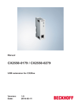
4.1 Configuration of the CX2100-0014 power supply unit
5
2
6
8
9
10
12
3
11
13
4
7
8
1
Fig.1: Configuration of the CX2100-0014 power supply unit.
Table3: Legend for the configuration.
No. Component Description
1 Multi-pole connection For connection to the basic CPU module on the right.
2 Ventilation openings Additional ventilation openings for passive cooling.
3
FSTN LCD display [}23]
Status display with 2 x 16 characters and backlight.
4
Enter key [}34]
Allows input and query of internal status values.
5
Selector switch [}34]
For navigation in menus.
6
Diagnostic LEDs [}41],
power supply terminal.
Diagnosis of the power supply for the Embedded PC and the
Terminal Bus. Status of the E-bus and K-bus communication.
7 Spring-loaded terminals,
+24V and 0V
Power supply for Embedded PC.
8 Terminal bus (K-bus or E-
bus)
Interface for EtherCAT Terminals or Bus Terminals. Data exchange
and supply.
9 Spring-loaded terminal,
+24V
Power supply for Bus Terminals via power contact.
10 Spring-loaded terminal, 0V Power supply for Bus Terminals via power contact.
11 Terminal release Releases the power supply terminal and therefore the Embedded
PC from the mounting rail.
12 Spring-loaded terminal, PE Spring-loaded terminal for power contact PE.
13 Power contacts, +24V,
0V, PE
Power contacts for Bus Terminals.

Product overview
CX2100-0014 13Version: 1.2
4.2 Name plate
The CX2100-0014 power supply unit features a name plate on the left-hand side of the housing.
1
2
5
3
4
6
Fig.2: CX2100-0014 power supply unit name plate.
Table4: Legend for the name plate.
No. Description
1 UL approval with prescribed information on power supply, fuse, temperature and cable
cross-sections.
2 Information on the power supply unit.
3 Information on:
• serial number,
• hardware version
• and date of manufacture.
4 Information on the model. The last four numerals relate to the configuration of the power
supply unit.
5 Vendor data including address.
6 CE conformity.

Commissioning
CX2100-001414 Version: 1.2
5 Commissioning
5.1 Mounting
This chapter describes how to install the power supply unit CX2100-0014. This documentation uses the
Embedded PC CX2020 to demonstrate the procedure.
5.1.1 Attaching the power supply unit
The power supply unit CX2100-0014 supplies power to Embedded PCs of the CX2000 series. The power
supply unit and the Embedded PC are connected via the multi-pole connector.
Proceed as follows:
1. Plug the power supply unit into the high-pole connection on the right on the basic CPU module.
2. Check whether the power supply unit is flush with the Embedded PC.
ð In the next step, you can install the bar clips.
5.1.2 Installing the bar clips
Usually, the connection between the modules is strong enough. However, the basic CPU module and the
attached modules may be subjected to shocks, vibrations or other impacts. The modules can be securely
connected to one another with the aid of bar clips.
Install the bar clips as follows:
1. Attach the bar clips at the top and bottom between the cooling fins.
2. Push the bar clips between the cooling fins of your devices, as shown in the image below.

Commissioning
CX2100-0014 15Version: 1.2
3. Check that the bar clips are flush.
ð The bar clips have been installed successfully, if they don't protrude and are level with the cooling fins of
your modules.
Once all modules are latched, the devices can be installed on the mounting rail.

Commissioning
CX2100-001416 Version: 1.2
5.1.3 Note the permissible installation positions
NOTE
Increased heat generation
If the minimum distances are not observed, the power supply unit and the Embedded PC may overheat.
• Leave at least 30 mm clearance above and below the Embedded PC. Ensure adequate ventilation.
Maintain the permissible ambient temperature in the vicinity of the power supply unit and Embedded PC.
Note the following specifications for the control cabinet:
• Maintain the permissible ambient temperature in the vicinity of the power supply unit and Embedded
PC. Measure the temperature below the Embedded PC at a distance of 30mm to the cooling fins, in
order to determine the ambient temperature correctly.
• Adhere to the minimum distances of 30mm above and below the Embedded PCs.
• Additional electrical equipment affects the heat generation in the control cabinet. Select a suitable
control cabinet enclosure depending on the application, or ensure that excess heat is dissipated from
the control cabinet.
The power supply unit CX2100-0014 and the Embedded PC are mounted horizontally on the mounting rail
as standard. A vertical or horizontal mounting position is only possible if the Embedded PC is actively
cooled.
Table5: Compatible Embedded PCs and permissible mounting positions.
CX2020 CX2030 CX2040 CX2020 with
fan option
CX2030 with
fan option
CX20x2
many-core
Horizontal
installation posi-
tion
x x x x x x
Vertical
mounting posi-
tion
- - x x x x
Ambient temper-
ature during op-
eration
-25°C…+60°C -25°C…+60°C -25°C…+60°C -25°C…+60°C -25°C…+60°C -25°C…+50°C
Horizontal installation position
Maintain the ambient temperatures. In addition, a minimum clearance of 30mm above and below the cooling
fins of the Embedded PCs is required in order to ensure adequate ventilation. This ensures optimum air flow
through the cooling fins of the Embedded PC.
Fig.3: Embedded PC CX2020, horizontal mounting position.
If there is a risk of vibrations or impact in the same direction as the mounting rail when the Embedded PC is
installed horizontally, the device must be secured with an additional bracket in order to prevent it slipping.

Commissioning
CX2100-0014 17Version: 1.2
Vertical mounting position
Maintain the ambient temperatures. The minimum distance of at least 30 mm above and below the cooling
fins of the Embedded PC must also be adhered to when the device is mounted vertically.
Ensure that any Bus Terminals connected to the Embedded PC are designed for operation in vertical
position.
Fig.4: CX2040 Embedded PC, vertical mounting position.
If you install the Embedded PC vertically, the device must be fastened properly to prevent it slipping off the
DIN rail. Install a bracket below the Embedded PC for this purpose.
Horizontal mounting position
Maintain the ambient temperatures. The minimum distance of at least 30mm above and below the cooling
fins of the Embedded PC must also be adhered to when the device is mounted horizontally.
Ensure that any Bus Terminals connected to the Embedded PC are designed for operation in horizontal
position.
Fig.5: CX2040 Embedded PC, horizontal mounting position.
If there is a risk of vibrations or impact in the same direction as the mounting rail when the Embedded PC is
installed horizontally, the device must be secured with an additional bracket in order to prevent it slipping.

Commissioning
CX2100-001418 Version: 1.2
5.1.4 Attaching on mounting rail
The housing is designed such that the Embedded PC can be pushed against the mounting rail and latched
onto it.
Requirements:
• Mounting rail of type TS35/7.5 or TS35/15 according to DIN EN 60715.
Secure the Embedded PC on the mounting rail as follows:
1. Unlock the latches at the top and bottom.
2. Place the Embedded PC at the front of the mounting rail. Slightly press the Embedded PC onto the
mounting rail until a soft click can be heard and the Embedded PC has latched.
3. Then lock the latches again.
ð You have installed the Embedded PC successfully. Double-check the correct installation and latching of
the Embedded PC on the mounting rail.

Commissioning
CX2100-0014 19Version: 1.2
5.1.5 Installing passive EtherCAT Terminals
Incorrectly installed passive EtherCAT Terminals
The E-bus signal between an Embedded PC and the EtherCAT Terminals can be impaired due to
incorrectly installed passive EtherCAT Terminals.
Passive EtherCAT Terminals should not be installed directly on the power supply unit.
EtherCAT Terminals that do not take part in active data exchange are referred to as passive terminals.
Passive EtherCAT Terminals have no process image and do not require current from the terminal bus (E-
bus).
Passive EtherCAT Terminals (e.g. EL9195) can be detected in TwinCAT. In the tree structure the EtherCAT
Terminal is displayed without process image, and the value in column “E-bus (mA)” does not change,
compared to the preceding EtherCAT Terminal.
Fig.6: Identifying a passive EtherCAT Terminal in TwinCAT.
The entry "Current consumption via E-Bus" in the technical data of an EtherCAT Terminal indicates whether
a particular EtherCAT Terminal requires power from the terminal bus (E-bus).
The following diagram shows the permissible installation of a passive EtherCAT Terminal. The passive
EtherCAT Terminal was not directly attached to the power supply unit.
Fig.7: Passive EtherCAT Terminals, permissible installation.
The following diagram shows the invalid installation of a passive EtherCAT Terminal.
Fig.8: Passive EtherCAT Terminals, invalid installation.

Commissioning
CX2100-001420 Version: 1.2
5.2 Power supply
This chapter describes how to connect the power supply unit CX2100-0014. This documentation uses the
Embedded PC CX2020 to demonstrate the procedure.
5.2.1 Connect Embedded PC
NOTE
Damage to the Embedded PCs
The Embedded PCs may be damaged during wiring.
• The cables for the power supply should only be connected in de-energized state.
The CX2100-0014 power supply units require an external voltage source, which provides 24VDC (-15% /
+20%).
The cabling of the Embedded PC in the control cabinet must be done in accordance with the standard EN
60204-1:2006 PELV = Protective Extra Low Voltage:
• The "PE" and "0V" conductors of the voltage source for a basic CPU module must be on the same
potential (connected in the control cabinet).
• Standard EN 60204-1:2006, section 6.4.1:b stipulates that one side of the circuit, or a point of the
energy source for this circuit must be connected to the protective earth conductor system.
Connection example with CX2020 basic CPU module and CX2100-0014 power supply unit:
Table6: Legend for the connection example.
No. Description
1 The upper spring-loaded terminals identified with "24V" and "0V" supply the basic CPU
module and the terminal bus (data transfer via K- or E-bus).
2 The spring-loaded terminals identified as "+", "-" and "PE" supply the Bus Terminals via
the power contacts and the sensors or actuators connected to the Bus Terminals.
/