
xx
WFM6120, WFM7020, WFM7120
WFM6100 Opt. MB, WFM7000 Opt. MB,
and WFM7100 Opt. MB
Waveform Monitors
Specifications and Performance Verification
ZZZ
Technical Reference
*P077008003*
077-0080-03


WFM6120, WFM7020, WFM7120
WFM6100 Opt. MB, WFM7000 Opt. MB,
and WFM7100 Opt. MB
Waveform Monitors
Specifications and Performance Verification
ZZZ
Technical Reference
xx
This document applies to firmware version 5.2.X.
Warning
The servicing instructions are for use by qualified personnel
only. To avoid per
sonal injury, do not perform any servicing
unless you are qualified to do so. Refer to all safety summaries
prior to performi
ng service.
www.tektronix.com
077-0080-03

Copyright © Tektronix. All rights reserved. Licensed software products are owned by Tektronix or its subsidiaries
or suppliers, and are protected by national copyright laws and international treaty provisions.
Tektronix products are covered by U.S. and foreign patents, issued and pending. Information in this publication
supersedes that in all previously published material. Specifications and price change privileges reserved.
TEKTRONIX and TEK are registered trademarks of Tektronix, Inc.
Contacting Tektronix
Tektronix, Inc.
14200 SW Karl Braun Drive
P.O. B o x 5 0 0
Beaverto
n, OR 97077
USA
For product information, sales, service, and technical support:
In North America, call 1-800-833-9200.
Worldwide, visit www.tektronix.com to find contacts in your area.

Warranty
Tektronix warrants that this product will be free from defects in materials and workmanship for a period of one (1)
year from the date of shipment. If any such product proves defective during this warranty p eriod, Tektronix, at its
option, either will repair the defective product without charge for parts and labor, or will provide a replacement
in exchange for the defective product. Parts, modules and replacement products used by Tektronix for warranty
work may be n
ew or reconditioned to like new performance. All replaced parts, modules and products become
the property of Tektronix.
In order to o
btain s ervice under this warranty, Customer must notify Tektronix of the defect before the expiration of
the warranty period and make suitable arrangements for the performance of service. Customer shall be responsible
for packaging and s hipping the defective product to the service center designated by Tektronix, with shipping
charges prepaid. Tektronix shall pay for the return of the product to Customer if the shipment is to a location within
the country in which the Tektronix service center is located. Customer shall be responsible for paying all shipping
charges, duties, taxes, and any other charges for products returned to any other locations.
This warranty shall not apply to any defect, failure or damage caused by improper use or improper or inadequate
maintenance and care. Tektronix shall not be obligated to furnish service under this warranty a) to repair damage
result
ing from attempts by personnel other than Tektronix representatives to install, repair or service the product;
b) to repair damage resulting from improper use or connection to incompatible equipment; c) to repair any damage
or malfunction caused by the use of non-Tektronix supplies; or d) to service a product that has been modified or
integrated with other products when the effect of such modification or integration increases the time or difficulty
of servicing the product.
THIS WARRANTY IS GIVEN BY TEKTRONIX WITH RESPECT TO THE PRODUCT IN LIEU OF ANY
OTHER WARRANTIES, EXPRESS OR IMPLIED. TEKTRONIX AND ITS VENDORS DISCLAIM ANY
IMPLIED WARRANTIES OF MERCHANTABILITY OR FITNESS FOR A PARTICULAR PURPOSE.
TEK
TRONIX’ RESPONSIBILITY TO REPAIR OR REPLACE DEFECTIVE PRODUCTS IS THE SOLE
AND EXCLUSIVE REMEDY PROVIDED TO THE CUSTOMER FOR BREACH OF THIS WARRANTY.
TEKTRONIX AND ITS VENDORS WILL N OT BE LIABLE FOR ANY INDIRECT, SPECIAL, INCIDENTAL,
OR CONSEQUENTIAL DAMAGES IRRESPECTIVE OF WHETHER TEKTRONIX OR THE VENDOR HAS
ADVANCE NOTICE OF THE POSSIBILITY OF SUCH DAMAGES.
[W2 – 15AUG04]


Table of Contents
General Safety Summary .......................................................................................... v
Environmental Considerations .................................................................................. vii
Preface .............................................................................................................. ix
Related Use
r Documents..................................................................................... ix
Related Reference Documents .............................................................................. ix
Specifications ....................................................................................................... 1
Electrical Specifications....................................................................................... 1
Physical Specifications....................................................................................... 35
Supported Input Formats and Allowed References ....................................................... 36
Alarms ......................................................................................................... 3
8
Performance Verification ......................................................................................... 43
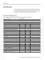
Test Records........................................................................................................ 44
Test Record - Function Tests ................................................................................ 44
Test Record - All Instruments ............................................................................... 46
Test Record - All Instruments (SD)......................................................................... 47
Test
Record - Option CPS ................................................................................... 48
Test Record - Options AD and DDE........................................................................ 49
Test Record - Option DS..................................................................................... 55
Incoming Inspection............................................................................................... 58
Required Equipment.......................................................................................... 58
Incoming Inspection Tests ................................................................................... 60
Vi
deo and General Performance Verification Procedures ..................................................... 81
Required Equipment.......................................................................................... 81
Instrument Tests............................................................................................... 83
SD Video Tests................................................................................................ 98
Tests for Instruments with Option CPS................................................................... 110
Signal Source Characterization for Eye Signal Bandwidth ............................................ 118
Audio Performance Verification Procedures.................................................................. 120
Required Equipment........................................................................................ 120
Tests for Waveform Monitors Equipped with Audio Options ......................................... 121
Additional Tests for Instruments Equipped with Options AD and DDE ............................. 129
Waveform Monitors Specifications and P erformance Verification i

Table of Contents
List of Figure
s
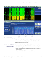
Figure 1: VM5000 HD Frequency Response display ......................................................... 87
Figure 2: Wi
ring diagram for LTC input/Ground Closure cable ............................................. 94
Figure 3: VM5000 SD Frequency Response display........................................................ 101
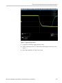
Figure 4: Trigger polarity positive................. ........................ ........................ ............ 105
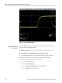
Figure 5: Trigger polarity negative............................................................................ 106
ii Waveform Monitors Specifications and Performance Verification

Table of Contents
List of Tables
Table 1: SDI Input Waveform Vertical Characteristics......................................................... 1
Table 2: Composite Analog Input Waveform Vertical Characteristics ....................................... 3
Table 3: Composite Analog Inputs A and B Physical Layer .................................................. 3
Table 4: Waveform Sweep (Horizontal) Deflection ............................................................ 4
Table 5: Eye Pattern Display ...................................................................................... 5
Table 6: Jitter Display (Option EYE and PHY).. .......... .......... .......... .......... ....................... 7
Table 7: Jitter Display (Option JIT) ................... .......... .................................. .......... .... 10
Table 8: Component Vector Mode............................................................................... 11
Table 9: Waveform Mode Filter Characteristics ..... .................. ................................ ........ 12
Table 10: SDI Lightning and Diamond Modes................................................................. 13
Table 11: Data Mode .............................................................................................. 13
Table 12: Composite Vector Mode .............................................................................. 13
Table 13: Arrowhead Mode (NTSC/PAL composite limit display).......................................... 14
Table 14: Bowtie Mode........................................................................................... 14
Table 15: Timing Display......................................................................................... 14
Table 16: Picture Mode ........................................................................................... 15
Table 17: Signal Level / Cable Length Detector ............................................................... 16
Table 18: Data error detection (EDH / Status, Under STATUS Button)..................................... 17
Table 19: ANC Data and ARIB.................................................................................. 17
Table 20: Audio Bar Displays.................................................................................... 17
Table 21: Audio Bar and Lissajous/Surround Display ........................................................ 20
Table 22: AV Delay display (Option AVD)..................................................................... 21
Table 23: AES Audio Inputs ..................................................................................... 21
Table 24: AES Audio Outputs (alternate function on second set of inputs) ................................ 22
Table 25: Embedded Audio Extraction ......................................................................... 23
Table 26: Analog Audio Inputs .................................................................................. 24
Table 27: Analog Au
dio Outputs ................................................................................ 25
Table 28: Dolby Digital (AC-3) Compressed Audio Monitoring (Opt. DDE) ............................. 26
Table 29: Dolby E and Extended Dolby Digital (AC-3) Compressed Audio Monitoring (Opt. DDE) .. 27
Table 30: Picture Monitor Outputs (VGA Pix Mon) .......................................................... 27
Table 31: LCD Display ........................................................................................... 28
Table 32: External XGA Output (EXT DISPLAY).... .............. .............. .............. .............. 28
Table 33: LTC Time Code Input / Ground Closures........................................................... 29
Table 34: VITC Decoding ........................................................................................ 30
Table 35: Serial Digital Video Interface (Input A, Input B) .................................................. 30
Table 36: Serial Video Output (Serial Out/SDI PixMon) ..................................................... 31
Table 37: External Reference .................................................................................... 32
Table 38: Ethernet................................................................................................. 33
Waveform Monitors Specifications and P erformance Verification iii

Table of Contents
Table 39: USB ..................................................................................................... 33
Table 40: Remote Port ............................................................................................ 33
Table 41: Power Source........................................................................................... 34
Table 42: Miscellaneous .......................................................................................... 35
Table 43: Physical Characteristics............................................................................... 35
Table 44: Environmental Performance.......................................................................... 35
Table 45: 25
Hz and 50 Hz Frame and Field Rates............................................................ 36
Table 46: 59.94 Hz, 23.98 Hz, and 29.97 Hz Frame and Field Rates........................................ 36
Table 47: 24 Hz, 30 Hz, and 60 Hz Frame and Field Rates................................................... 37
Table 48: Supported Standards................................................................................... 37
Table 49: Common Alarms....................................................................................... 38
Table 50: HD Specific Alarms (WFM7120, WFM7020 Opt. HD) .......................................... 40
Table 51
:SDSpecific Alarms.................................................................................... 40
Table 52: Composite Specific Alarms (Opt. CPS)............................................................. 40
Table 53: Audio Alarms (Opts. AD and DDE) ................................................................ 40
Table 54: Additional Audio Alarms (Opt. DDE) .............................................................. 41
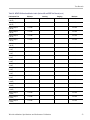
Table 55: WFM6120, WFM7020, and WFM7120 Waveform Monitor Functional Test Record ......... 44
Table 56: WFM6120, WFM7000, and WFM7120 Waveform Monitor Video Performance Test
Reco
rd.......................................................................................................... 46
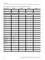
Table 57: WFM6120, WFM7020, and WFM7120 Waveform Monitor Video Performance Test
Record.......................................................................................................... 47
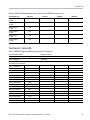
Table 58: WFM7120 Waveform Monitor Video Performance Test Record (Options CPS) .............. 48
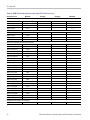
Table 59: WFM7120 Waveform Monitor Audio Options AD and DDE Test Record ..................... 49
Table 60: WFM7120 Waveform Monitor Audio Option DS Test Record .................................. 55
Ta
ble 61: Required Test Equipment............................................................................. 58
Table 62: LCD Visual Defects ................................................................................... 62
Table 63: Diagnostics Limits..................................................................................... 64
Table 64: Required Test Equipment (Video and General Performance)..................................... 81
Table 65: Oscilloscope Settings for Serial Output Amplitude................ ................ ...... ........ 104
Table 66: Generator Characterization ......................................................................... 119
Table 67: Required Test Equipment (Audio)................................................................. 120
iv Waveform Monitors Specifications and Performance Verification

General Safety Summary
General Safet
ySummary
Review the fo
llowing safety precautions to avoid injury and prevent damage to
this product or any products connected to it.
To avoid pot
ential hazards, use this product only as specified.
Only qualified personnel should perform service procedures.
To Avoid Fi
re or Personal
Injury
Use proper
power cord. Use only the power cord specified for this product and
certified for the country of use.
Ground th
e product. This product is grounded through the grounding conductor
of the power cord. To avoid electric shock, the grounding conductor must be
connected to earth ground. Before making connections to the input or output
terminals of the product, ensure that the product is properly grounded.
Observe all terminal ratings. To avoid fire or shock hazard, observe all ratings
and markings on the product. Consult the product manual for further ratings
information before making connections to the product.
Do not apply a potential to any terminal, including the common terminal, that
exceeds the maximum rating of that terminal.
Power disconnect. The power cord disconnects the product from the power source.
Do not block the power cord; it must remain accessible to the user at all times.
Do not operate without covers. Do not operate this product with covers or panels
removed.
Do not operate with suspected failures. If you suspect that there is damage to this
product, have it inspected by qualified service personnel.
Avoid exposed circuitry. Do not touch exposed connections and components when
power is present.
Replace batteries properly. Replace batteries only with the specified type and
rating.
Recharge batteries properly. Recharge batteries for the recommende d charge cycle
only.
Use proper AC adapter. Use only the AC adapter specified for this product.
Use proper fuse. Use only the fuse type and rating specifi ed for this product.
Waveform Monitors Specifications and P erformance Verification v

General Safety Summary
Do not operate i
n wet/damp conditions.
Do not operate in an explosive atmosphere.
Keep product surfaces clean and dry.
Provide prop
er ventilation. Refer to the manual’s installation instructions for
details on installing the product so it has proper ventilation.
TermsinThisManual
These terms may appear in this manual:
WARNING.
Warning statements identify conditions or practices that could result
in injury or loss of life.
CAUTION
. Caution statements identify conditions or practices that could result in
damage to this product or other property.
Symbols and Terms on the
Product
These t
erms may appear on the product:
DANGER indicates an injury hazard immediately accessible as you read
the ma
rking.
WARNING indicates an injury hazard not immediately accessible as you
read
the marking.
CAUTION indicates a hazard to property including the product.
The following symbol(s) may appear on the product:
vi Waveform Monitors Specifications and Performance Verification

Environmental Considerations
This section provides information about the environmental impact of the product.
Product End-of-Life
Handling
Observe the following guidelines when recycling an instrument or component:
Equipment Recycling. Production of this equipment required the extraction and
use of natural resources. The equipment may c ontain substances that could be
harmful to
the environment or human health if improperly handled at the product’s
end of life. In order to avoid release of such substances into the environment and
to reduce the use of natural resources, we encourage you to recycle this product
in an appropriate system that will ensure that most of the materials are reused or
recycled appropriately.
This sym
bol indicates that this product complies with the European Union’s
requirements according to Directive 2002/96/EC on waste electrical and
electronic equipment (WEEE). For information about recycling options, check
the Supp
ort/Service section of the Tektronix Web site (ww w.tektronix.com).
Battery Recycling. This product may contain a Nickel Cadmium (NiCd) or
lithium ion (Li-ion) rechargeable battery, which must be recycled or disposed of
prope
rly. Please properly d ispose of or recycle the battery according to local
government regulations.
Mercury Notification. This product uses an LCD backlight lamp that contains
mercury. Disposal may be regulated due to environmental considerations.
Please contact your local authorities or, within the United States, the Electronics
Ind
ustries Alliance (www.eiae.org) for disposal or recycling information.
Restriction of Hazardous
Substances
This product has been classified as Monitoring and Control equipment, and is
outside the scope of the 2002/95/EC RoHS Directive. This product is known to
co
ntain lead, cadmium, mercury, and hexavalent chromium.
Waveform Monitors Specifications and P erformance Verification vii

Environmen tal Considerations
viii Waveform Monitors Specifications and Performance Verification

Preface
This reference document provides technical information about using the
WFM6120, WFM7020, and WFM7120 Series multi-format waveform monitors.
Related User Documents
The following related user documents are available:
WFM6120, WFM7020, and WFM7120 Waveform Monitors Release Notes
(Tektronix part number 077-0226-XX). This document describes any known
problems
or behaviors that you might encounter while using the waveform
monitor.
WFM6120,
WFM7020, and WFM7120 Waveform Monitors Quick Start
User Manual (Tektronix part numbers: English, 071-2223-XX; Japanese
071-2224-XX; Simplified Chinese, 071-2225-XX). This document is a printed
Quick Start User Manual and contains the basic operating information for
the instrument. Included in the manual is a CD-ROM containing PDFs of
the user documents.
WFM6120, WFM7020, and WFM7120 Waveform Monitors Technical
Reference (Tektronix part number 077-0079-XX). This document contains the
deta
iled operating information for the instrument.
WFM6120, WFM7020, and WFM7120 Waveform Monitors Service Manual
(Tek
tronix part number 077-0081-XX). This document provides servicing
information for the waveform monitor and is intended for qualified service
personnel only.
Related Reference Documents
The following related reference documents are available at the Tektronix, Inc.
Web site (www.tektronix.com):
Preventing Illegal Colors. This application note describes how the Diamond,
Arrowhead, and Lightning displays can be used to help prevent the undesired
impact of color gamut violations and to simplify the assessment of proper
gamut compliance.
Understanding Colors and Gamut. This poster provides a large visual display
of how the Diamond, Arrowhead, and Lightning displays can be used to h elp
prevent the undesired impact of color gamut violations.
A Guide to Standard and High Definition Digital Video Measurements.
This book is a primer for understanding the basics for making standard and
high-definition, digital-video measurements.
Waveform Monitors Specifications and P erformance Verification ix

Preface
Analog and Digi
tal Audio Monitoring. This application note describes how
to monitor a nalog and digital audio signals. Also discussed are specific
differences in the methods used to monitor analog audio versus digital audio,
and how to plan the transition from monitoring analog audio to monitoring
digital audio.
Audio Monitoring. This application note describes balanced and unbalanced
audio signals, and explains the physical and electrical characteristics and the
specific strength and weaknesses of the different digital audio signal formats.
Monitoring Surround Sound Audio. This application note describes the basics
of 5.1-channel surround sound audio and how to use the Surround Sound
display t
o visualize key audio-level and phase relationships in this audio
format.
x Waveform Monitors Specifications and Performance Verification

Specifications
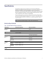
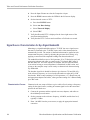
The following tables list the specifications for the Tektronix WFM6120,
WFM7020, and WFM7120 Waveform Monitors. Items listed in the Performance
Requirement
column are generally quantitative and can be tested by the
Performance Verification procedure in Section 2 of this manual. Items listed in the
Reference Information column are useful operating parameters that have typical
values; information in this column is not guaranteed.
The specifications listed in the Electrical Specifications portion of these tables
apply over an ambient temperature range of +0 °C to +40 °C. The rated accuracies
are valid when the instrument is calibrated in an ambient temperature range of
+20 °C to +30 °C.
NOTE. Al
lHDspecifications apply to 3 Gb/s unless noted otherwise.
Electrical Specifications
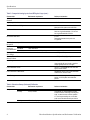
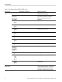
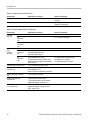
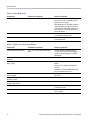
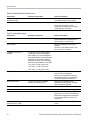
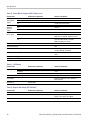
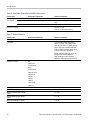
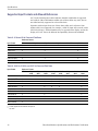
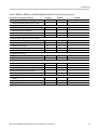
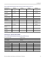
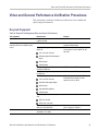
Table 1: SDI Input Waveform Vertical Characteristics
Characteristic Performance requirement Reference inform ation
Using graticule or cursor. Measure in YPbPr
mode.
1X
± 0.5% of 700 mV full scale mode
Vertical
Measurement
Accur
acy
5X
± 0.2% of 700 mV full scale mode
Gain
X1, X2, X5, and X10
Variable Gain Range, Typical 0.25X to 1.8X, typical (variable gain multiplied
by
fixed gain to get total gain).
Luminance
Ch
annel (Y)
50
kHz to 30 MHz, ± 0.5%
50
kHz to 60 MHz for 1080P 60/59/50 dual
link formats.
Frequency
Re
sponse -
HD
Chrominance
Channels (Pb,
P
r)
50 kHz to 15 MHz, ± 0.5% 50 kHz to 30 MHz for 1080P 60/59/50 dual
link formats.
Luminance
Channel (Y)
50 kHz to 5.75 MHz, ± 0.5%
Frequency
Response -
SD
Chrominance
Channels (Pb,
Pr)
50 kHz to 2.75 MHz, ± 0.5%
YPbPr to RGB Conversion
Accuracy
0.1%, nominal
Waveform Monitors Specifications and P erformance Verification 1

Specifications
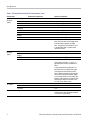
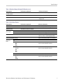
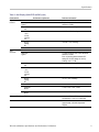
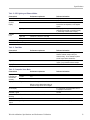
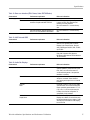
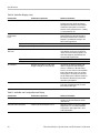
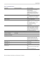
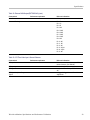
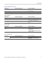
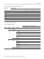
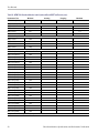
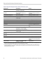
Table 1: SDI Input Waveform Vertical Characteristics (cont.)
Characteristic Performance requirement Reference information
Sine-squared bars
Preshoot
SD ≤ 0.3% peak (2T5 bar)
HD
≤ 0.5% peak (2T30 bar)
Overshoot
SD ≤ 0.3% peak (2T5 bar)
HD
≤ 0.5% peak (2T30 bar)
Ringing
SD ≤ 0.8% peak-peak (2T5 bar)
Step
Response,
Typical
HD
≤ 0.8% peak-peak (2T30 bar)
Most of the error seen on the display comes
from the inherent ringing in the d igital
data. The response of the monitor is close
to the theoretical limit of a perfect sinx/x
reconstruction filter.
Blackman pulse
Baseline
Ringing
SD ≤ 0.6% peak-peak (2T5)
Pulse
Response,
Typical
HD
≤ 0.7% peak-peak (2T30)
Pulse-to-bar ratio 0.995:1 to 1.005:1 on
appropriate Sine Squared or Blackman 2T
pulse.
A sine-squared pulse near Nyquist is not
band-limited and so inherently has ringing
much larger than the waveform monitor
filter. A three term Blackman pulse with the
same HAD has much less inherent ringing,
so it is a better choice for most testing. See
Digital to Analog Conversion, Data and Filter
Requirements, SMPTE Journal Mar 1995,
Vol. 104, Fibush, Baker, Penny.
Field Rate
0.1%
Tilt, Typical
Line Rate
0.1%
Off Screen Recovery, Typical 0.1% variation in baseline of a 5 MHz
modulated pulse when positioned anywhere
on screen at any gain setting.
2 Waveform Monitors Specifications and Performance Verification

Specifications
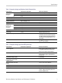
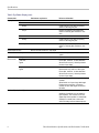
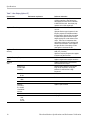
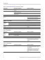
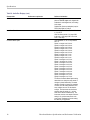
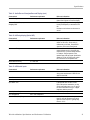
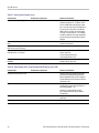
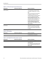
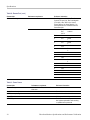
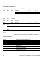
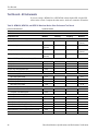
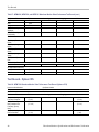
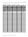
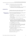
Table 2: Compos
ite Analog Input Waveform Vertical Characteristics
Characteristic Performance requirement Reference inform ation
Measured usin
g cursors or graticules
1X
±1%
Vertical
Measurement
Accuracy
5X
±1%
Gain
X1, X2, X5, and X10
Variable G
ain Range, Nominal
0.25X to 1.8X
Frequency Response
Flat to 5.7
5MHz,±1%
Delay Variation over Frequency ± 10 ns to 5.75 MHz Typically ± 2.5 ns
Pulse to bar ratio 0.99:1 to 1.01:1
Preshoo
t
≤ 1%
Overshoot ≤ 1%
Transient
Response on
Sine Squ
ared
2T4 Pulse
Ringin
g
≤ 1%
Field R
ate Tilt
< 0.5% With D C Restore Fast or Off
Line R
ate Tilt
< 0.5% With D C Restore Fast or Off
Off Screen Recovery ≤ 0.5% variation in baseline of a Chroma
modulated pulse when positioned anywhere
on sc
reen. Signal must meet specification for
Video Maximum O perating Amplitude. Any
gain setting.
SNR 60 dB
RMS
minimum, relative to 700 mv for
PAL
or 714 mv for NTSC.
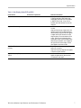
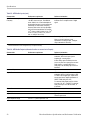
Table 3: Composite Analog Inputs A and B Physical Layer
Characteristic Performance requirement Reference information
Formats Supported NTSC, NTSC no setup, and PAL, I, B, D, G,
H. Complies with RS170A & ITU-R BT.471
Manual or auto detect of input standard
Internal Referenc e
Proper horizontal and vertical synchronization
with a composite signal of appropriate line
and field rate
Input Dynamic Range, Typical ± 6 dB range
Video Maximum Operating
Amplitudewith Clamp Off (DC
Coupled), Typical
–1.8 V to +2.2 V (all inputs) DC +peak AC
Maximum Absolute Video Input
Voltage
–6.0 V to +6.0 V (DC + peak AC)
Input Type
Passive loop-through 75 Ω compensated
DC Input Impedance 20 kΩ
Return Loss Typically > 46 dB to 6 MHz, > 40 dB to
10 MHz. Typically 35 dB with power off for
standard amplitude video
Waveform Monitors Specifications and P erformance Verification 3

Specifications
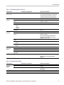
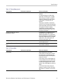
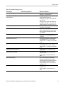
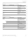
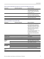
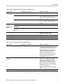
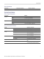
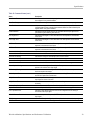
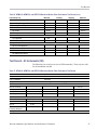
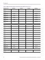
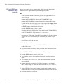
Table 3: Composite Analog Inputs A and B Physical Layer (cont.)
Characteristic Performance requirement Reference information
Video Input Crosstalk Between
Channels
≥ 60 dB to 6 MHz
Loop through Isolation ≥ 70 dB to 6 MHz
DC Offset with Restore Off, Typical
≤ 20 mV
Measured in full screen mode at X5 Gain
DC Restore Modes Fast, Slow, and Off modes
Slow has a typical bandwidth of 10 Hz Fast
has a typical bandwidth of 500 Hz
DC Restore Offset Error
≤ 2mV
Registration between back porch and
0 V graticule
DC Offset Between Inputs W ith
Restore Off
≤ 7mV
Fast Mode
> 95% attenuation
DC Restore
50 Hz and
60 Hz Attenuation
Slow Mode < 10% attenuation, < 10% peaking
Blanking Shift with 10% to 90%
APL Change
≤ 1 IRE (7 mV PAL)
Blanking Shift with Presence and
Absence of Burst
≤ 1 IRE (7 mV PAL), Typic ally 0 mV
Lock Range ± 50 ppm, remains locked
Vector typically OK to ± 80 ppm. w aveform
display typically locked to ± 200 ppm
Lock in Presence of Hum 700 mV
p-p
, on full amplitued 100% color bar
signal, remains locked
Lock in Presence of White Noise S ignal/Noise ratio of 32 dB, 5 MHz bandwidth
on black burst, remains locked
Color Framing Correct color framing detected for signals
having < 45 SCH phase error with burst
present
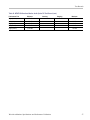
Table 4: Waveform Sweep (Horizontal) Deflection
Characteristic Performance requirement Reference information
Accuracy
± 0.5%, all rates Line sweeps for 1080P 60/59/50 dual link
formats are shown with image scanning time
scale. In these formats, each link operates
at
1
/
2
the image scanning rate, so link time
scale is twice the indicated time per division.
Sweep
Linearity
0.2% of time displayed on screen
Fully digital system
4 Waveform Monitors Specifications and Performance Verification
Page is loading ...
Page is loading ...
Page is loading ...
Page is loading ...
Page is loading ...
Page is loading ...
Page is loading ...
Page is loading ...
Page is loading ...
Page is loading ...
Page is loading ...
Page is loading ...
Page is loading ...
Page is loading ...
Page is loading ...
Page is loading ...
Page is loading ...
Page is loading ...
Page is loading ...
Page is loading ...
Page is loading ...
Page is loading ...
Page is loading ...
Page is loading ...
Page is loading ...
Page is loading ...
Page is loading ...
Page is loading ...
Page is loading ...
Page is loading ...
Page is loading ...
Page is loading ...
Page is loading ...
Page is loading ...
Page is loading ...
Page is loading ...
Page is loading ...
Page is loading ...
Page is loading ...
Page is loading ...
Page is loading ...
Page is loading ...
Page is loading ...
Page is loading ...
Page is loading ...
Page is loading ...
Page is loading ...
Page is loading ...
Page is loading ...
Page is loading ...
Page is loading ...
Page is loading ...
Page is loading ...
Page is loading ...
Page is loading ...
Page is loading ...
Page is loading ...
Page is loading ...
Page is loading ...
Page is loading ...
Page is loading ...
Page is loading ...
Page is loading ...
Page is loading ...
Page is loading ...
Page is loading ...
Page is loading ...
Page is loading ...
Page is loading ...
Page is loading ...
Page is loading ...
Page is loading ...
Page is loading ...
Page is loading ...
Page is loading ...
Page is loading ...
Page is loading ...
Page is loading ...
Page is loading ...
Page is loading ...
Page is loading ...
Page is loading ...
Page is loading ...
Page is loading ...
Page is loading ...
Page is loading ...
Page is loading ...
Page is loading ...
Page is loading ...
Page is loading ...
Page is loading ...
Page is loading ...
Page is loading ...
Page is loading ...
Page is loading ...
Page is loading ...
Page is loading ...
Page is loading ...
Page is loading ...
Page is loading ...
Page is loading ...
Page is loading ...
Page is loading ...
Page is loading ...
Page is loading ...
Page is loading ...
Page is loading ...
Page is loading ...
Page is loading ...
Page is loading ...
Page is loading ...
Page is loading ...
Page is loading ...
Page is loading ...
Page is loading ...
Page is loading ...
Page is loading ...
Page is loading ...
Page is loading ...
Page is loading ...
Page is loading ...
Page is loading ...
Page is loading ...
Page is loading ...
Page is loading ...
Page is loading ...
Page is loading ...
Page is loading ...
Page is loading ...
Page is loading ...
Page is loading ...
Page is loading ...
-
 1
1
-
 2
2
-
 3
3
-
 4
4
-
 5
5
-
 6
6
-
 7
7
-
 8
8
-
 9
9
-
 10
10
-
 11
11
-
 12
12
-
 13
13
-
 14
14
-
 15
15
-
 16
16
-
 17
17
-
 18
18
-
 19
19
-
 20
20
-
 21
21
-
 22
22
-
 23
23
-
 24
24
-
 25
25
-
 26
26
-
 27
27
-
 28
28
-
 29
29
-
 30
30
-
 31
31
-
 32
32
-
 33
33
-
 34
34
-
 35
35
-
 36
36
-
 37
37
-
 38
38
-
 39
39
-
 40
40
-
 41
41
-
 42
42
-
 43
43
-
 44
44
-
 45
45
-
 46
46
-
 47
47
-
 48
48
-
 49
49
-
 50
50
-
 51
51
-
 52
52
-
 53
53
-
 54
54
-
 55
55
-
 56
56
-
 57
57
-
 58
58
-
 59
59
-
 60
60
-
 61
61
-
 62
62
-
 63
63
-
 64
64
-
 65
65
-
 66
66
-
 67
67
-
 68
68
-
 69
69
-
 70
70
-
 71
71
-
 72
72
-
 73
73
-
 74
74
-
 75
75
-
 76
76
-
 77
77
-
 78
78
-
 79
79
-
 80
80
-
 81
81
-
 82
82
-
 83
83
-
 84
84
-
 85
85
-
 86
86
-
 87
87
-
 88
88
-
 89
89
-
 90
90
-
 91
91
-
 92
92
-
 93
93
-
 94
94
-
 95
95
-
 96
96
-
 97
97
-
 98
98
-
 99
99
-
 100
100
-
 101
101
-
 102
102
-
 103
103
-
 104
104
-
 105
105
-
 106
106
-
 107
107
-
 108
108
-
 109
109
-
 110
110
-
 111
111
-
 112
112
-
 113
113
-
 114
114
-
 115
115
-
 116
116
-
 117
117
-
 118
118
-
 119
119
-
 120
120
-
 121
121
-
 122
122
-
 123
123
-
 124
124
-
 125
125
-
 126
126
-
 127
127
-
 128
128
-
 129
129
-
 130
130
-
 131
131
-
 132
132
-
 133
133
-
 134
134
-
 135
135
-
 136
136
-
 137
137
-
 138
138
-
 139
139
-
 140
140
-
 141
141
-
 142
142
-
 143
143
-
 144
144
-
 145
145
-
 146
146
-
 147
147
-
 148
148
-
 149
149
-
 150
150
-
 151
151
-
 152
152


Tektronix WFM6100 Opt. MB Technical Reference
- Type
- Technical Reference
- This manual is also suitable for
Ask a question and I''ll find the answer in the document
Finding information in a document is now easier with AI
Related papers
-
Tektronix WFM7100 Opt. MB Quick Start User Manual
-
-
-
-
-
-
-
-
-
Other documents
-
 Analog Arts SG884 User manual
-
 ADS Technologies API-558-EFS Supplementary Manual
-
Sony LMD-1420MD User manual
-
NEO Bridge X_NEO User manual
-
GE X-ray Accessories Quick start guide
-
Furman Sound MS2A-1 User manual
-
AVLink PG-HD1X User manual
-
 Whirlwind AESDA User manual
-
-
Barco DCS-200 Quick start guide


