Page is loading ...

NM.1010LF2
788395
NU-NM.1010LF2/1212
6 Rue Gustave Eiffel
91420 MORANGIS- France
http://www.expert-tool.com
NU-E201804/0115
E201804

EN
WARNING
IMPORTANT SAFETY INFORMATION ENCLOSED.
READ THIS MANUAL BEFORE OPERATING THE MACHINE.
IT IS THE RESPONSIBILITY OF THE EMPLOYER TO PLACE THE INFORMATION IN THIS MANUAL
INTO THE HANDS OF THE OPERATOR.
FAILURE TO OBSERVE THE FOLLOWING WARNINGS COULD RESULT IN INJURY.
SAFETY RULES
• This tester complies with EN61243-3.
• This tester can be used outdoors. lts operating
temperature is -10°C to 55°C and its operating altitude
is up to 2000m.
• This tester is designed for "TOUCH" testing only.
Do not keep continuous contact with the circuit under
test for more than 30 secs, especially to high voltage.
• Test on known live circuits to familiar yourself with the
tester’s response.
• Do not use the tester if the tester or its test lead looks
damaged, or if you suspect that the tester is not
operating properly.
• When using the probes, keep your ngers behind the
nger guards on the tester.
• Keep the tester clean and dry. Do not use the tester with
wet hands.
• Do not tamper with the internai circuit of the tester.
• Use caution when working with voltage above
30V ac rms, 42V peak, or 60V de. Such voltages pose a
shock hazard.
• To avoid electric shock, do not touch any naked
conductor with your hand or skin, and do not ground
yourself while using the tester.
• Before use, carry out the self-test for the tester and
verity the tester’s operation by measuring a known
voltage.
• CAT Ill: Measurement Category Ill is for measurements
performed in the building installation. Examples are
measurements on distribution boards, circuit breakers,
wiring, including cables, bus-bars, junction boxes,
switches, socket-outlets in the xed installation, and
equipment for industrial use and sorne other
equipment, for example, stationary motors with
permanent connection to the xed installation.
Do not use the tester for measurements within
Measurement Categories IV.
Warning
Continuous contact with the circuit under test will
cause severe damage and injury. Any testing contacts
must not exceed a 30 secs, duration.
SYMBOL EXPLANATION
Alternating Current
Direct Current
Both direct and alternating current
Caution, risk of danger, refer to the operating manual
before use.
Caution, risk of electric shock.
Conforms to European Union directives
Earth {ground) Terminal
The equipment is protected throughout by double
insulation or reinforced insulation.
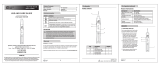
STRUCTURE
1. Voltage Level lndicator LEDs
2. AC Voltage lndicator LEDs 1 Polarity lndicator LEDs /6V Voltage
Level lndicator LEDs
3. Finger Guard
4. « + « Test Probe
5. « - « Test Probe
OPERATING INSTRUCTION
1. Before use, you should install two button cells
in the tester. To do it, use a suitable
screwdriver to remove the screw on the
battery holder and then remove the battery
holder. Place two new 1.5V LR44 button cells
in the battery holder in correct direction
as indicated in the following gure.
Reinstall the battery holder and the screw.
Button Cells
Battery Holder with
Button Cells lnstalled

After you install the button cells, the tester will
go into self-test mode automatically. If the LEDs sequentially
ash once from the 12V indicator LED to the 400V indicator
LED and then all LEDs remain off, the tester passes the self-
test. If the tester does not self test or if the 12V lndicator LED
ashes ve times after the self-test, the button cells are low
and must be replaced immediately.
Note: The interval belween self-tests must be at least
about 15 secs; otherwise the tester will not self
test.
2. Before each use, a self-test has to be carried out,
and moreover, you must verity the tester’s
operation by measuring a known voltage.
If the tester operates abnormally ln the self-test
or in the voltage measurement, do not use the
tester.
How to do the self-tests
Touch the two probes together for about 3 secs, the tester
will go lnto the self-test mode. If the LEDs sequentially ash
once from the 12V lndicator LED to the 400V indicator LED
and then all LEDs remain off, the tester passes the self-test.
Note: The interval between self-tests must be at least about
15 secs; otherwise the tester will not self test.
3. Connect the two test probes across the circuit or
source to be tested.
4. The LEDs will indlcate the voltage of the circuit or
source under test.
. If the voltage being measured is an ac voltage, both the
«+» LED and the «-» LED will light up.
. If the voltage being measured is a dc voltage, the
«+» LED will light up if the «+» test probe has
been connected to the positive terminal of the
circuit under test; and the «-» LED will light
up If the «+» test probe has been connected to the
negative terminal of the circuit.
5. If the circuit under test is without power, the tester may go
into self-test mode, and the LEDs may sequentially ash
once from the 12V indicator LED to the 400V lndicator
LED.
6. If the tester has no button cell installed, it can still
measure dc or ac voltage, but lt will not self test.
GENERAL SPECIFICATION
Voltage Range: 6V- 400V OC/AC
Frequency Range for AC Voltage Measurements 50Hz - 60Hz
Max. Test Current ( at 400V ): is < 3.5mA ED(DT) = 30s
Operating Temperature: -10°C~55°C
Power Supply 1.5V button cell, LR44 or equivalent, 2 pieces
IP Degree: IP54
Measurement Category: CAT Ill 400V
TECHNICAL SPECIFICATION
LOW BATTERY INDICATION
1. During the tester’s self test, the LEDs sequentially ash
once from the 12V lndicator LED to the 400V indicator
LED; and after that, if the 12V indicator LED ashes
ve times immediately, the button cells are not high
enough and should be replaced immediately. About how
to replace the button cells, please see step 1 of
«OPERATING INSTRUCTION».
2. If the tester does not go into self-test mode after you
touch the two probes together for about 3 secs, the
button cells are not high enough and should be
replaced immediately.
Warning:
Remove the button cells if you does not use the tester in a
long period of time.
MAINTENANCE
Periodically wipe the case with a damp cloth and a little
mild detergent. Do not use abrasives or solvents.
To avoid short circuit or damage, do not let any liquid enter
the case.
DECLARATION
1. This Instruction Sheet is subject to change without
notice.
2. Our company will not take the other responsibilities for
any loss.
3. The contents of this instruction Sheet can not be used as
the reason to use the tester for any special application.
Voltage Range Indication
6V/12V/24V/50V/120V/230V/400V The LEDs light up to indicate
the voltage reading.
DISPOSAL OF THIS ARTICLE
Dear Customer,
If you at some point intend to dispose of this article, then please keep in mind that many of its
components consist of valuable materials, which can be recycled.
Please do not discharge it in the garbage bin, but check with your local council for recycllng
facilities in your area.

Stanley France S.A.S.
6 Rue Gustave Eiffel
91420 MORANGIS- France
http://www.expert-tool.com
Stanley Works Asia Pacic Pte Ltd
No. 25 Senoko South Road,
Woodlands East Industrial Estate,
Singapore 758081
Tel: 65-6752 2001 Fax: 65-6752 2697
Email: [email protected]
Website: http://sea.stanleyblackanddecker.com/
/