Page is loading ...

Crestron CEN-ERFGW-POE
Extended Range RF Wireless Gateway
Operations & Installation Guide

(Continued on following page)
Regulatory Compliance
As of the date of manufacture, the CEN-ERFGW-POE has been tested and found to comply with
specifications for CE marking and standards per EMC and Radiocommunications Compliance Labelling.
Federal Communications Commission (FCC) Compliance Statement
This device complies with part 15 of the FCC Rules. Operation is subject to the following conditions:
(1) This device may not cause harmful interference and (2) this device must accept any interference received,
including interference that may cause undesired operation.
CAUTION: Changes or modifications not expressly approved by the manufacturer responsible for
compliance could void the user’s authority to operate the equipment.
NOTE: This equipment has been tested and found to comply with the limits for a Class B digital device,
pursuant to part 15 of the FCC Rules. These limits are designed to provide reasonable protection against
harmful interference in a residential installation. This equipment generates, uses and can radiate radio
frequency energy and, if not installed and used in accordance with the instructions, may cause harmful
interference to radio communications. However, there is no guarantee that interference will not occur in a
particular installation. If this equipment does cause harmful interference to radio or television reception,
which can be determined by turning the equipment off and on, the user is encouraged to try to correct the
interference by one or more of the following measures:
• Reorient or relocate the receiving antenna
• Increase the separation between the equipment and receiver
• Connect the equipment into an outlet on a circuit different from that to which the receiver is connected
• Consult the dealer or an experienced radio/TV technician for help

The specific patents that cover Crestron products are listed at patents.crestron.com.
Crestron, the Crestron logo, Crestron Studio, Crestron Toolbox, Cresnet, infiNET and VT Pro-e are either trademarks or
registered trademarks of Crestron Electronics, Inc. in the United States and/or other countries. Windows is either a
trademark or registered trademark of Microsoft Corporation in the United States and/or other countries. Other
trademarks, registered trademarks and trade names may be used in this document to refer to either the entities claiming
the marks and names or their products. Crestron disclaims any proprietary interest in the marks and names of others.
Crestron is not responsible for errors in typography or photography.
This document was written by the Technical Publications department at Crestron.
©2013 Crestron Electronics, Inc.
Regulatory Compliance (Continued)
Industry Canada (IC) Compliance Statement
This device complies with Industry Canada license-exempt RSS standard(s). Operation is subject to the
following two conditions: (1) this device may not cause interference, and (2) this device must accept any
interference, including interference that may cause undesired operation of the device.
Under Industry Canada regulations, this radio transmitter may only operate using an antenna of a type and
maximum (or lesser) gain approved for the transmitter by Industry Canada. To reduce potential radio
interference to other users, the antenna type and its gain should be so chosen that the equivalent isotropically
radiated power (e.i.r.p.) is not more than that necessary for successful communication.
This radio transmitter, IC: 5683C-CWD6660, has been approved by Industry Canada to operate with the
antenna types listed below with the maximum permissible gain and required antenna impedance for each
antenna type indicated. Antenna types not included in this list, having a gain greater than the maximum gain
indicated for that type, are strictly prohibited for use with this device.
Antenna Type: Dipole, Maximum permissible antenna gain: 2.5 dBi, Impedance: 50 Ohms
Industrie Canada (IC) Déclaration de conformité
Le présent appareil est conforme aux CNR d'Industrie Canada applicables aux appareils radio exempts de
license. L'exploitation est autorisée aux deux conditions suivantes : (1) l'appareil ne doit pas produire de
brouillage, et (2) l'utilisateur de l'appareil doit accepter tout brouillage radioélectrique subi, même si le
brouillage est susceptible d'en compromettre le fonctionnement.
Conformément à la réglementation d'Industrie Canada, le présent émetteur radio peut fonctionner avec une
antenne d'un type et d'un gain maximal (ou inférieur) approuvé pour l'émetteur par Industrie Canada. Dans le
but de réduire les risques de brouillage radioélectrique à l'intention des autres utilisateurs, il faut choisir le
type d'antenne et son gain de sorte que la puissance isotrope rayonnée équivalente (p.i.r.e.) ne dépasse pas
l'intensité nécessaire à l'établissement d'une communication satisfaisante.
Le présent émetteur radio , IC: 5683C-CWD6660, a été approuvé par Industrie Canada pour fonctionner avec
les types d'antenne énumérés ci-dessous et ayant un gain admissible maximal et l'impédance requise pour
chaque type d'antenne. Les types d'antenne non inclus dans cette liste, ou dont le gain est supérieur au gain
maximal indiqué, sont strictement interdits pour l'exploitation de l'émetteur.
Type d'antenne: Dipole, Gain admissible maximal: 2.5 dBi, Impédance: 50 Ohms
To satisfy RF exposure requirements, this device and its antenna must operate with a separation distance of
at least 20 centimeters from all persons and must not be colocated or operating in conjunction with any other
antenna or transmitter.


Crestron CEN-ERFGW-POE Extended Range Wireless Gateway
Operations & Installation Guide – DOC. 7158B Contents • i
Contents
Extended Range RF Wireless Gateway: CEN-ERFGW-POE 1
Introduction ............................................................................................................................... 1
Features and Functions ................................................................................................ 1
Specifications .............................................................................................................. 4
Physical Description .................................................................................................... 7
Setup ........................................................................................................................................ 10
Network Wiring ......................................................................................................... 10
Identity Code ............................................................................................................. 11
Installation ................................................................................................................. 12
Hardware Hookup ..................................................................................................... 13
Uploading and Upgrading ........................................................................................................ 14
Establishing Communication ..................................................................................... 14
Programs and Firmware ............................................................................................ 15
Program Checks ........................................................................................................ 16
Operation ................................................................................................................................. 18
Problem Solving ...................................................................................................................... 21
Troubleshooting ......................................................................................................... 21
Check Network Wiring .............................................................................................. 24
Reference Documents ................................................................................................ 25
Further Inquiries ........................................................................................................ 25
Future Updates .......................................................................................................... 26
Appendix A: The RF Spectrum .............................................................................................. 27
Appendix B: Optimum RF Reception Guidelines .................................................................. 28
Minimize Interference ............................................................................................... 28
Gateway Placement ................................................................................................... 28
Antenna Orientation .................................................................................................. 29
Return and Warranty Policies .................................................................................................. 31
Merchandise Returns / Repair Service ...................................................................... 31
Crestron Limited Warranty ........................................................................................ 31


Crestron CEN-ERFGW-POE Extended Range Wireless Gateway
Operations & Installation Guide – DOC. 7158B Wireless Gateway: CEN-ERFGW-POE • 1
• 2-way “Extended Range” RF wireless transceiver/gateway
• Supports up to 16 touch screens and remotes
• Dynamic discovery for fast, easy setup
• “Wi-Fi friendly” channel selection
• Built-in RF network diagnostics
• CEN-ERFGW-POE: 100 to 200 feet (~30 to 61 meters) range
indoors, 1000 feet (~305 meters) outdoors
• CENI-ERFGW-POE: 50 to 100 feet (~15 to 30 meters) range
indoors, 340 feet (~104 meters) outdoors
Extended Range RF Wireless
Gateway: CEN-ERFGW-POE
Introduction
The CEN-ERFGW-POE gateway is a 2-way RF transceiver that enables
wireless communication and management for up to 16 Crestron
®
“Extended Range” wireless touch screens and remotes. It is compatible
with the TST-600 and TPS-6X Wireless Touch Screens and
UFO-WPR-3ER Waterproof Wireless Remote (all sold separately). A
single wire links the CEN-ERFGW-POE to a Crestron control system via
Cresnet
®
or high speed Ethernet with PoE (Power over Ethernet).
The CEN-ERFGW-POE and the CENI-ERFGW-POE (international
version) are functionally identical. For simplicity within this guide, the
term “CEN-ERFGW-POE” is used except where noted.
Features and Functions
(Continued on following page)

Extended Range Wireless Gateway Crestron CEN-ERFGW-POE
2 • Wireless Gateway: CEN-ERFGW-POE Operations & Installation Guide – DOC. 7158B
• Supports roaming for extended coverage
2
• Antenna extendable using optional ANT-EXT
• Crestron Toolbox™ software configuration and management
• Cresnet or Ethernet control system interface
• Single wire Cresnet or PoE network powered
• Compatible with TST-600, TPS-6X and UFO-WPR-3ER (all
sold separately)
Features and Functions
(Continued)
Extended Range 2.4 GHz RF Technology
Crestron Extended Range (ER) wireless technology (formerly called
“High Powered RF”) affords robust bidirectional wireless
communications over an impressive distance.
1
Roaming capability allows
for even greater coverage using up to eight CEN-ERFGW-POE
gateways.
2
“Wi-Fi friendly” RF technology permits selection from 16
ISM
3
channels within the 2.4 GHz spectrum to minimize the possibility
of interference with other RF equipment including 802.11 devices.
The CEN-ERFGW-POE continuously monitors each device on the
network, diligently keeping track when any device goes to sleep, shuts
down or wanders out of range, restoring communications seamlessly
when the device reappears on the network. The control data to and from
each associated device is passed cleanly and quickly through the gateway
without any cumbersome processing to affect performance. Excessive
network traffic and noise are combated using intelligent data routing to
ensure every control signal is delivered intact to its intended destination
without interruption.
1. CEN-ERFGW-POE range approximately 100-200 feet (~30-61 meters) indoors
and up to 1000 feet (~305 meters) outdoors. CENI-ERFGW-POE range
approximately 50-100 feet (~15-30 meters) indoors and up to 340 feet (~104
meters) outdoors.
2. The TST-600 does not currently support roaming.
3. Industrial, Scientific and Medical, refers to frequency range used for unlicensed
communication applications, such as Wi-Fi.

Crestron CEN-ERFGW-POE Extended Range Wireless Gateway
Operations & Installation Guide – DOC. 7158B Wireless Gateway: CEN-ERFGW-POE • 3
Easy Setup
Setting up a network of ER wireless devices is simple, utilizing dynamic
discovery to locate and acquire each RF device automatically. Up to 16
ER wireless touch screens and remotes can be linked to a control system
via a single CEN-ERFGW-POE gateway. Additional gateways must be
installed to support more devices, with up to 16 gateways possible in a
complete system (RF conditions allowing).
Single Wire Hookup
Wired communications between the CEN-ERFGW-POE gateway and the
control system can be via Cresnet or Ethernet, with power for the
gateway delivered over the same Cresnet or Ethernet connection. Power
over Ethernet (PoE) simply requires the presence of an 802.3af or 802.3at
PoE power source. Crestron offers the PWE-4803RU PoE Injector,
which connects in-line with the Ethernet cable, allowing for installation
at any convenient location between the gateway and the network switch.
The PWE-4803RU is capable of powering a single gateway and is
available separately or packaged with the gateway as model
CEN-ERFGW-POE-PWE.
Crestron also offers Ethernet switches with built-in PoE (models
CEN-SW-POE-5, CEN-SWPOE-16 and CEN-SWPOE-24, all sold
separately), affording a complete high performance networking solution
capable of providing PoE for multiple gateways and other PoE devices.
Using an Ethernet switch with built-in PoE eliminates the need for
separate PoE injectors.

Extended Range Wireless Gateway Crestron CEN-ERFGW-POE
4 • Wireless Gateway: CEN-ERFGW-POE Operations & Installation Guide – DOC. 7158B
Specifications
Specifications for the CEN-ERFGW-POE are listed in the following
table.
CEN-ERFGW-POE Specifications
SPECIFICATION DETAILS
Wireless
RF Transceiver
2-way RF, 2.4 GHz ISM Channels
11-26 (2400 to 2483.5 MHz);
IEEE 802.15.4 compliant
Transmitting Power
CEN-ERFGW-POE 170.2 mW (Ch. 11), 110.7 mW
(Ch. 12-24), 23.4 mW (Ch. 25),
0.6 mW (Ch. 26) @ high setting;
3.2 mW (Ch. 11-25), 0.6 mW (Ch.
26) @ low setting
CENI-ERFGW-POE
8 mW (Ch. 11-26)
@ high setting;
3 mW (Ch. 11-26)
@ low setting
Range (typical)
CEN-ERFGW-POE 100 to 200 feet (~30 to 61
meters) indoor, 1000 feet (~305
meters) outdoor, subject to
site-specific conditions
CENI-ERFGW-POE 50 to 100 feet (~15 to 30 meters)
indoor, 340 feet (~104 meters)
outdoor, subject to
site-specific conditions
Roaming
Supports roaming among up to
eight RF gateways
1
;
Maximum 16 “ER” wireless
devices per gateway or roaming
network
(Continued on following page)

Crestron CEN-ERFGW-POE Extended Range Wireless Gateway
Operations & Installation Guide – DOC. 7158B Wireless Gateway: CEN-ERFGW-POE • 5
CEN-ERFGW-POE Specifications (Continued)
SPECIFICATION DETAILS
Communications
Ethernet 10/100 Mbps, auto-switching,
auto-negotiating, auto-
discovery, full/half duplex,
DHCP, IEEE 802.3af and
802.3at Type 1compliant
Unit ships with DHCP enabled.
Cresnet
Supports Cresnet slave mode
Power Requirements
2
Power over Ethernet IEEE 802.3af (802.3at Type 1)
Class 1 PoE powered device
Cresnet Power Usage 3 watts
(0.13 amps @ 24 Vdc)
Default Net ID
2F
Minimum Firmware
CEN-ERFGW-POE
Version 1.000.0041 or later
CENI-ERFGW-POE Version 1.000.0051 or later
Environmental
Temperature
41º to 104º F (5º to 40º C)
Humidity
10% to 90% RH
(non-condensing)
Heat Dissipation 11 BTU/Hr
Enclosure
Construction Aluminum with polycarbonate
label overlay and integral
mounting flanges
Mounting Freestanding, surface mount or
attach to a single rack rail
(Continued on following page)

Extended Range Wireless Gateway Crestron CEN-ERFGW-POE
6 • Wireless Gateway: CEN-ERFGW-POE Operations & Installation Guide – DOC. 7158B
CEN-ERFGW-POE Specifications (Continued)
SPECIFICATION DETAILS
Dimensions
(without antenna)
Height 6.41 in (163 mm)
Width
3.91 in (100 mm)
Depth
1.43 in (37 mm)
Weight
14 oz (386g)
Available Models
CEN-ERFGW-POE
Extended Range RF Wireless
Gateway
CEN-ERFGW-POE-PWE
Extended Range RF Wireless
Gateway with PoE Injector
CENI-ERFGW-POE Extended Range RF Wireless
Gateway
(International Version)
CENI-ERFGW-POE-
PWE
Extended Range RF Wireless
Gateway with PoE Injector
(International Version)
Included Accessory
PWE-4803RU
PoE Injector (included with
models
CEN-ERFGW-POE-PWE and
CENI-ERFGW-POE-PWE only)
Available Accessories
ANT-EXT
Antenna Extender
CEN-SW-POE-5
5-Port PoE Switch
CEN-SWPOE-16
16-Port Managed PoE Switch
CEN-SWPOE-24
24-Port Managed PoE Switch
CRESNET Cresnet Control Cable
PWE-4803RU
PoE Injector
1. The TST-600 does not currently support roaming.
2. May be powered by PoE or Cresnet network power, not both.

Crestron CEN-ERFGW-POE Extended Range Wireless Gateway
Operations & Installation Guide – DOC. 7158B Wireless Gateway: CEN-ERFGW-POE • 7
Physical Description
This section provides information on the connections, controls and
indicators available on the CEN-ERFGW-POE.
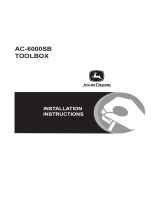
CEN-ERFGW-POE Overall Dimensions
(Top, Front, Side and Bottom Views)
1
2
3
5
6
7
4
1
5.30 in
(135 mm)
3.50 in
(89 mm)
1.43 in
(37 mm)
6.41 in
(163 mm)
8
9
3.91 in
(100 mm)

Extended Range Wireless Gateway Crestron CEN-ERFGW-POE
8 • Wireless Gateway: CEN-ERFGW-POE Operations & Installation Guide – DOC. 7158B
Connectors, Controls & Indicators
# CONNECTORS
1
,
CONTROLS &
INDICATORS
DESCRIPTION
1 ANTENNA (1) Connection for supplied
antenna
2
PWR LED
(1) Green LED, indicates DC
power supplied from Cresnet
network or PoE
3 NET LED (1) Yellow LED, indicates
communication with the
Cresnet system
4 RXD LED (1) Red LED, indicates data is
being received from wireless
network devices
5 TXD LED (1) Red LED, indicates data is
being transmitted to wireless
network devices
6
ACQUIRE
(Button and LED)
(1) Recessed push button with
red LED, used to set up
connections with wireless
devices
7 SETUP
(Button and LED)
(1) Recessed push button with
red LED, used to set up
connection with the control
system via Cresnet or Ethernet
(Continued on following page)

Crestron CEN-ERFGW-POE Extended Range Wireless Gateway
Operations & Installation Guide – DOC. 7158B Wireless Gateway: CEN-ERFGW-POE • 9
Connectors, Controls & Indicators (Continued)
# CONNECTORS
1
,
CONTROLS &
INDICATORS
DESCRIPTION
8 LAN PoE
2, 3
Green
LED
Amber
LED
Pin 8
Pin 1
(1) 8-wire RJ-45 female, with
two LED indicators;
10BASE-T/100BASE-TX
Ethernet port,
Power over Ethernet compliant;
Green LED indicates link
status;
Amber LED indicates Ethernet
activity
PIN
SIGNAL
PIN
SIGNAL
1
TX +
5
N/C
2
TX -
6
RC -
3
RC +
7
N/C
4
N/C
8
N/C
9 NET
3
G Z Y
24
(1) 4-pin 3.5 mm detachable
terminal block;
Cresnet slave port, connects to
Cresnet control network
24: Power (24 Vdc)
Y: Data
Z: Data
G
: Ground
1. An interface connector for the NET port is provided with the unit.
2. Power should be supplied through either the LAN PoE port or the NET port but
not both.
3. The pin out table indicates signal connections. DC power applied by Ethernet
power sourcing equipment (PSE) can connect to either signal pins or N/C pins.

Extended Range Wireless Gateway Crestron CEN-ERFGW-POE
10 • Wireless Gateway: CEN-ERFGW-POE Operations & Installation Guide – DOC. 7158B
Setup
Network Wiring
When wiring the Cresnet network, consider the following:
• Use Crestron Certified Wire.
• Use Crestron power supplies for Crestron equipment.
• Provide sufficient power to the system.
CAUTION: Insufficient power can lead to unpredictable results
or damage to the equipment. Please use the Crestron Power
Calculator to help calculate how much power is needed for the
system (
www.crestron.com/calculators).
For Cresnet networks with 20 or more devices, use a Cresnet
Hub/Repeater (CNXHUB) to maintain signal quality.
For more details, refer to “Check Network Wiring” on page 24.
The CEN-ERFGW-POE can also use high-speed Ethernet for
communications between the device and a control system, computer,
media server and other IP-based devices.
For general information on connecting Ethernet devices in a Crestron
system, refer to the latest version of the Crestron e-Control
Reference
Guide (Doc. 6052), which is available from the Crestron Web site
(
www.crestron.com/manuals).

Crestron CEN-ERFGW-POE Extended Range Wireless Gateway
Operations & Installation Guide – DOC. 7158B Wireless Gateway: CEN-ERFGW-POE • 11
Identity Code
NOTE: The latest software can be downloaded from the Crestron Web
site (www.crestron.com/software).
Net ID
The Net ID of the CEN-ERFGW-POE has been factory set to 2F. The
Net IDs of multiple CEN-ERFGW-POE devices in the same system must
be unique. Net IDs are changed from a personal computer (PC) via
Crestron Toolbox™ (refer to “Establishing Communication” on page
14).
When setting the Net ID, consider the following:
• The Net ID of each unit must match an ID code specified in the
Crestron Studio™ or SIMPL Windows program.
• Each network device must have a unique Net ID.
For more details, refer to the Crestron Toolbox help file.
IP ID
The IP ID is set within the CEN-ERFGW-POE’s IP table using Crestron
Toolbox. For information on setting an IP table, refer to the Crestron
Toolbox help file. The IP IDs of multiple CEN-ERFGW-POE devices in
the same system must be unique.
When setting the IP ID, consider the following:
• The IP ID of each unit must match an IP ID specified in the
Crestron Studio or SIMPL Windows program.
• Each device using IP to communicate with a control system must
have a unique IP ID.

Extended Range Wireless Gateway Crestron CEN-ERFGW-POE
12 • Wireless Gateway: CEN-ERFGW-POE Operations & Installation Guide – DOC. 7158B
Installation
Ventilation
To prevent overheating, do not operate this product in an area that
exceeds the environmental temperature range listed in the table of
specifications. Consider using forced air ventilation and/or incrementing
the spacing between units to reduce overheating. Consideration must be
given if installed in a closed or multi-unit rack assembly since the
operating ambient temperature of the environment may be greater than
the room ambient temperature. Contact with thermal insulating materials
should be avoided on all sides of the unit.
Placement
Tips
When installing a CEN-ERFGW-POE near another CEN-ERFGW-POE,
for optimum performance, keep the following in mind:
• Do not place multiple gateways on the same channel. Refer to
“Appendix A: The RF Spectrum” on page 27 for details.
• Gateways on adjacent channels should be at least 12 feet
(3.7 meters) apart.
• Gateways on non-adjacent channels should be at least three feet
(0.9 meters) apart.
When installing a CEN-ERFGW-POE near a Wi-Fi access point, for
optimum performance, keep the following in mind:
• Gateways on RF channels adjacent to operating Wi-Fi channels
should be placed at least 12 feet (3.7 meters) from the nearest
Wi-Fi access point.
• Gateways on RF channels that are non-adjacent to Wi-Fi channels
should be located at least six feet (1.8 meters) from the nearest
Wi-Fi access point.
For more information on RF channels and their interaction with the
Wi-Fi spectrum, refer to “Appendix A: The RF Spectrum” on page 27.
For additional information on optimal gateway placement, refer to
“Appendix B: Optimum RF Reception Guidelines” on page 28.
If the gateway is to be installed inside an equipment rack, the
ANT-EXT-5 and ANT-EXT-10 Antenna Extenders (both sold
separately) should be used to extend the antenna to a place outside of the
rack.

Crestron CEN-ERFGW-POE Extended Range Wireless Gateway
Operations & Installation Guide – DOC. 7158B Wireless Gateway: CEN-ERFGW-POE • 13
Hardware Hookup
Make the necessary connections as called out in the illustrations that
follow this paragraph. Refer to “Network Wiring” on page 10 before
attaching the 4-position terminal block connector. Apply power after all
connections have been made.
NOTE: Power should be supplied through either the LAN PoE port or
the NET port but not both.
When making connections to the CEN-ERFGW-POE, use Crestron
power supplies for Crestron equipment.
Hardware Connections for the CEN-ERFGW-POE (Top View)
Antenna:
For Included Antenna
Hardware Connections for the CEN-ERFGW-POE (Bottom View)
LAN PoE:
10BASE-T / 100BASE-TX
Ethernet to LAN
NET:
T
o Control System and
Other Cresnet Devices
NOTE: Antenna must be attached directly to the antenna connector.
Alternatively, it can be extended with an optional ANT-EXT-5 or
ANT-EXT-10 Antenna Extender (both sold separately).
NOTE: Although both the LAN PoE and NET ports can be used for
configuration, there can only be one control connection to the control
system.

Extended Range Wireless Gateway Crestron CEN-ERFGW-POE
14 • Wireless Gateway: CEN-ERFGW-POE Operations & Installation Guide – DOC. 7158B
Uploading and Upgrading
Crestron recommends using the latest programming software and that
each device contains the latest firmware to take advantage of the most
recently released features. However, before attempting to upload or
upgrade it is necessary to establish communication. Once communication
has been established, files (for example, programs or firmware) can be
transferred to the control system (and/or device). Finally, program checks
can be performed (such as changing the device ID or creating an IP table)
to ensure proper functioning.
NOTE: Crestron software and any files on the Web site are for
authorized Crestron dealers and Crestron Service Providers (CSPs) only.
New users must register to obtain access to certain areas of the site
(including the FTP site).
Establishing Communication
Use Crestron Toolbox for communicating with the CEN-ERFGW-POE;
refer to the Crestron Toolbox help file for details. There are two methods
of communication: indirect and TCP/IP.
Indirect
Indirect Communication
PC Running
Crestron Toolbox
Serial,
or USB
LAN
Cresnet
Control
System
C OM PU TER
PWR
N ET
H W-R
SW-R
ACQUIRE
AC TIVITY
CEN-ERFGW-POE
PWR
N ET
AC TIVITY
ACQUIRE
SETU P
C EN -R FG W-EX
LAN PoE
2W
N ET
G Z Y 24
CRESTRO N
CEN-ERFGW-POE connects to control system via Cresnet:
1. Click Tools | System Info.
2. Click the
icon.
3. For Connection Type, select Cresnet ID. In the Through
drop-down menu, select the control system.
4. Click OK. Communications are confirmed when the device
information is displayed.
/