Page is loading ...

Compatibility
This locomotive is capable of operating on
AC or DC output power supplies (see page
28 for a complete list of compatible
transformers and wiring instructions) and
indoors or outdoors. M.T.H. does not
recommend operating the locomotive in
inclement weather and strongly suggests that
it not be left out in the elements. The
locomotive will negotiate an R2 G-Gauge
curve track or switch. Additional features
may be utilized when controlling the engine
with M.T.H.’s Digital Command System
(DCS).
PLEASE READ BEFORE USE
4-8-4 Gs-2/Gs-4
Steam Locomotive
OPERATOR’S MANUAL

Table of Contents
Set Up Checklist................................................................................................... 3
Tender Coupler Installation...................................................................3
Lubrication.............................................................................................5
Priming The Smoke Unit........................................................................5
Checking The Battery........................................................................... 6
Placing The Engine On The Track.........................................................6
Basic Operation.....................................................................................................7
Activating Features Using DC Power.....................................................7
Using DCS with DC Power....................................................................8
Activating Features Using AC Power....................................................9
Manual Volume Adjustment..................................................................10
Proto-Sound 2.0 Operating Instructions ......................................................... 11
Activating Proto-Sound 2.0 Conventional Mode Features................... 11
Freight Yard Sounds (FYS/PSA)...........................................................12
Speed Control........................................................................................ 14
Locking Locomotive Into A Direction.................................................. 15
Reset To Factory Default.......................................................................15
Automatic Sound Effects.......................................................................15
Maintenance......................................................................................................... 16
Lubricating and Greasing Instructions...................................................16
Traction Tire Replacement Instructions.................................................19
Light Bulb Replacement Instructions.....................................................20
Self Charging Battery Back-Up.............................................................21
ProtoSmoke® Unit Operation................................................................22
Troubleshooting Proto-Sound® 2.0 Problems.......................................23
Transformer Compatibility and Wiring Chart.......................................26
Additional Features Accessible With The DCS System..................................28
Addendum- Polarity Switch...............................................................................29
Service & Warranty Information........................................................................30
Limited One-Year Warranty...............................................................................30
This product may be protected by one or more of the following patents: 6,019,289; 6,280,278; 6,281, 606;
6,291,263; 6,457,681; 6,491,263; 6,604,641; 6,619,594; 6,624,537; 6,655,640.
2005, M.T.H. Electric Trains, Columbia, MD 21046
CAUTION: ELECTRICALLY OPERATED PRODUCT:
Not recommended for children under 10 years of age. M.T.H. recommends adult supervision with children ages 10 - 16.
As with all electric products, precautions should be observed during handling and use to reduce the risk of electric shock.
WARNING: When using electrical products, basic safety precautions should be observed, including the following:
Read this manual thoroughly before using this device.
M.T.H. recommends that all users and persons supervising use examine the hobby transformer and other electronic equipment
periodically for conditions that may result in the risk of fire, electric shock, or injury to persons, such as damage to the primary
cord, plug blades, housing, output jacks or other parts. In the event such conditions exist, the train set should not be used until
properly repaired.
Do not operate your layout unattended. Obstructed accessories or stalled trains may overheat, resulting in damage to your layout.
This train set is intended for indoor or outdoor use. Do not use if water is present. Serious injury or fatality may result.
l
l
l
l Do not operate the hobby transformer with damaged cord, plug, switches, buttons or case.

4-8-4 Gs-2/Gs-4 Steam Locomotive 3
Set Up Checklist
•
Install the tender coupler
• Lubricate the locomotive
• Prime the smoke unit
•
Check to see whether the batteries need to be charged for full sound effects
• Apply power to run as described in the Basic Operating Section of this manual
Installing The Tender Coupler
This RailKing One-Gauge locomotive can be equipped with three different types of
G-Gauge couplers - an M.T.H. knuckle coupler, an M.T.H. hook & loop coupler or a
1/32nd Kadee coupler. For your convenience, the M.T.H. knuckle and the hook & loop
couplers have been included with your locomotive. The Kadee type must be the 1/32nd
size and can be purchased from a Kadee coupler retailer. Prior to installation, you will
need to install the Kadee coupler base included inside your locomotive’s packaging.
Both the standard knuckle and the hook and loop coupler designs attach to the tender
chassis in the same manner as seen in Figures 1 and 2.
Knuckle Coupler
In Standard Factory Position “A”
Figure 1: Knuckle Coupler Position “A”
Hook & Loop Coupler
Figure 2

Installing The Tender Coupler (cont’d)
4 4-8-4 Gs-2/Gs-4 Steam Locomotive
If the locomotive is to be mated up with a
different manufacturer’s G-Gauge
locomotive, freight or passenger car, the
knuckle coupler assembly may need to be
relocated on the coupler armature as seen in
Fig. 3. The second lower location or
position “B” is on the bottom of the
armature extending from the truck rather
than the default top position “A” which is on
top of the armature. Simply unscrew the
coupler shaft from the armature, separate the
coupler knuckle (attached by screw & nut)
from this shaft and relocate to the bottom of
the shaft. Reassemble.
Note: When the standard knuckle coupler is
installed in position B, the knuckle pin must
be cut off as shown in Fig. 3. The coupler
pin has been “scored” so that it can be easily
cut off with a pair of snippers.
The Hook and Loop coupler mounts to the
truck armature in the same manner as the
Knuckle Coupler. Note that the mounting
screw is located behind the rear axle as seen
in Figure 4.
If a Kadee Coupler is to be installed, remove the M.T.H. knuckle or hook & loop coupler
and install the Kadee Coupler base included in your locomotive packaging as seen in
Figure 5a. Once the coupler base is installed, attach the Kadee Coupler onto the mount
(See Fig. 5b) by following the Kadee Coupler’s installation guide.
Hook and Loop and
Knuckle Couplers
Attach To Truck
Armature Via This
Mounting Screw
Figure 4
Standard Knuckle Coupler
In Position “B”
Armature
Must Be
Cut Off
Here To
Avoid
Interfering
With Track
Roadbed
Figure 3
Install Kadee Coupler
Mount into mounting
holes on tender chassis
Figure 5a
Install Kadee Coupler
Onto Coupler Mount
Using Kadee supplied
screws
Figure 5b

4-8-4 Gs-2/Gs-4 Steam Locomotive 5
Lubrication
You should lubricate the engine to prevent it from squeaking. Use
light household oil and follow the lubrication points marked “L” in
Fig. 6. Do not over-oil. Use only a drop or two on each pivot point.
Priming The Smoke Unit
When preparing to run this engine, add 30-40
drops of smoke fluid through the smokestack.
We recommend M.T.H. ProtoSmoke,
Seuthe, LGB, or LVTS fluids. Do not
overfill the unit or the fluid may leak out
and coat the interior engine components.
If you choose not to add the fluid (or have
already added the fluid but choose to run
smoke-free), rotate the smoke unit knob located
inside the boiler front (see Fig. 7) to the off
position (rotate clockwise). If you wish to
regulate the smoke output intensity, turn the
knob between full counterclockwise and full
clockwise until the desired smoke output is
reached. Failure either to add fluid to the unit or to turn it off may damage the
smoke unit heating element and/or wicking material.
While M.T.H. does not recommend operating outdoors in inclement weather (in order to
prevent possible damage to the electronics), we have included for your convenience, a
smoke stack “cap” inside your locomotive packaging. This cap should be inserted on the
smoke stack to prevent moisture from entering the smoke unit chamber.
DO NOT
OVER OIL
Running the engine without a primed
smoke unit may cause damage
Figure 7: Smoke Unit Control
Figure 6: Lubrication Points on the Locomotive
Lubricate Side Rods and Linkage (L) (Both Sides)
(L)
(L)
(L)
Lubricate Axle Bushings (L)
Smoke unit control

6 4-8-4 Gs-2/Gs-4 Steam Locomotive
Checking The Battery
You may find, if your locomotive was built several months before you set it up, that the
rechargeable batteries have run down and need to be charged before operating. If you
notice that the sounds are garbled, test and charge the engine as described in the
"Self-Charging Battery Back-Up" on page 23.
Placing The Engine On The Track
Place the engine on the track, then insert the reverse unit plug that extends out of the
tender into the receptacle at the back of the boiler cab (Figure 8). WARNING: DO NOT
CONNECT THIS ENGINE TO A TENDER FROM ANOTHER ENGINE; IT MAY
CAUSE SERIOUS DAMAGE.
Connect the draw bar between the engine and tender.
At this point, you are ready to begin running your engine.
Plug Tender Plug into
Boiler Socket at back of cab.
Figure 8: Connecting Tender Hanress

4-8-4 Gs-2/Gs-4 Steam Locomotive 7
Basic Operation
RailKing One-Gauge locomotives can be operated with AC or DC power output
transformers. When using DC output power supplies, the user can only control the
lcomotive speed and direction. The locomotive will still make engine sounds but no bell
or whistle control is possible when using a DC output power supply unless the user
wishes to hook up the power supply to M.T.H.’s separately sold Digital Command
System (see below).
As with all G-Gauge locomotives, the Throttle knob or handle controls how fast your
train will travel.
Throttle To increase or decrease track voltage, and therefore train speed, turn or slide
the throttle control knob. Turning clockwise will increase voltage and speed, while
turning counterclockwise will decrease voltage and speed. Because your RailKing
One-Gauge locomotive is equipped with M.T.H.’s Proto-Speed Control feature, the
engine will maintain the speed you set after you release the throttle until you turn it again
to slow down or speed up the locomotive. This feature works very similarly to the cruise
control system found in automobiles and allows the engine to maintain its speed even as
it enters curves, traverses grades or coasts down inclines.
Direction - There are two ways to change a locomotive’s direction when operating the
engine with a DC power supply.
1. Slow the locomotive down using the throttle knob until the engine comes to a
complete stop but power still remains on the track. Slide the direction switch on
the power supply to the opposite direction and increase the throttle setting again
to allow the locomotive to begin running in the opposite direction.
2. While the locomotive is running, slide the direction switch on the power
supply to the opposite direction. The locomotive will slow to a gradual stop and
then reverse direction and slowly gain speed until it is again travelling at its
original speed prior to the direction switch change.
Activating Features Using DC Power

8 4-8-4 Gs-2/Gs-4 Steam Locomotive
Using DCS With DC Power
M.T.H.’s revolutionary Digital Command System, or DCS, allows users to
control their RailKing One-Gauge locomotives in a command control
environment. User’s can remotely access hundreds of features inside each
RailKing One-Gauge locomotive with the wireless remote control. Digital
signalling and an easy-to-use interface make using DCS a snap. More
information on DCS can be found on page 30 or by visiting
www.protosound2.com.

4-8-4 Gs-2/Gs-4 Steam Locomotive 9
Activating Features Using AC Power
Using an AC output transformer equipped with a whistle and bell button will unlock
dozens of features inside your RailKing One-Gauge locomotive. Operation is simple by
following the simple steps below and on the following pages.
Start Up - Turn the throttle knob up ½-way, until the engine headlight shines bright.
Put the engine into motion by pressing the Direction button on your transformer once.
(hold it for approximately 1 second)
If the engine does not begin to move as soon as you firmly press the Direction button,
you may not have sent enough voltage to the track to make the train move. Turn the
throttle up a bit higher until the train begins to move.
Throttle - To increase or decrease track
voltage, and therefore train speed, turn the
throttle control knob. Turning clockwise
will increase voltage and speed, while
turning counterclockwise will decrease
voltage and speed. The engine will
maintain the speed you set after you
release the throttle until you turn it again to
change the voltage and speed.
Bell - To sound the bell, in an engine
equipped with a bell firmly press and
release the Bell button. To turn the bell off,
press and release the Bell button again.
The bell will continue to ring from the time you turn it on until you press and release the
button again to turn it off.
Horn/Whistle - To sound the whistle, firmly press the Horn/Whistle button. The whistle
will sound for as long as you continue to depress the button. It will stop when you
release the button. Three whistle/horn endings are available depending on how long the
whistle/horn button is depressed. A short button push will cause the whistle/horn to
quickly turn off. A 3 second or 6 second button push will create two distinct
whistle/horn endings.
Direction - Your train is programmed to start in neutral. The train will always cycle
neutral-forward-neutral-reverse with each press and release of the direction button. The
engine is programmed to restart in neutral each time the track voltage is turned off for 25
seconds or more.
Cycle Phases
Neutral
Neutral
ForwardReverse

10 4-8-4 Gs-2/Gs-4 Steam Locomotive
Manual Volume Adjustment - To adjust the volume of all sounds made by this engine,
turn the master volume control
knob located inside the boiler
front clockwise to increase the
volume and counter-clockwise to
decrease the volume.
Figure 9: Manual Volume Adjustment
Volume Control Knob

4-8-4 Gs-2/Gs-4 Steam Locomotive 11
The following pages contain the operating instructions for Proto-Sound 2.0 RailKing
One-Gauge locomotives when operated with AC output transfomrers in conventional
mode only. Instructions for accessing DCS command mode features accompany the DCS
Remote Control System equipment. These features are only available when using an AC
Transformer equipped with a whistle and bell button.
Proto-Sound 2.0 features are activated by sequences of Bell and Horn button pushes
described below. Please read the full descriptions of each feature before using it. To use
these buttons to activate features rather than to blow the horn or ring the bell, you should
tap the buttons very quickly with a ½-second pause between button presses. You may
need to practice your timing to make this work smoothly.
Proto-Sound 2.0
Operating Instructions
Timing Chart
Total Time Lapse: 1 Seconds
½
Press
Horn
Short &
Firm
½ Sec.
Pause
½ Sec.
Pause
Press
Bell
Short &
Firm
Press
Bell
Short &
Firm
Feature to Be Activated Button Code:
Freight Yard/Passenger Station Announcements
Speed Control On/Off
Lock into a Direction
Reset to Factory Defaults
1 Bell, 2 Horns
1 Horn, 2 Bells (from Neutral only)
1 Horn, 3 Bells
1 Horn, 5 Bells (from Neutral only)
Activating Proto-Sound 2.0 Conventional
Mode Features (AC Operation Only)

12 4-8-4 Gs-2/Gs-4 Steam Locomotive
Your engine is equipped with a sound package of freight yard sounds that you can play
when you pull into a yard. Each sequence described below will play as long as it is left
on, randomly generating sounds, but be sure to allow approximately 30 seconds between
the button pushes described below to allow the FYS/PSA sufficient time to run through
each sequence.
• To cue the sound system to play the FYS/PSA, quickly but firmly tap the Bell
button once followed by 2 quick taps of the Horn button while the engine is
moving. Tap the buttons quickly but allow approximately ½ second between
each press.
•
Press the Direction button once to stop the engine. This will trigger the first
sequence of FYS/PSA. The reverse unit is temporarily disabled so that the train
will not move as you use the Direction button to trigger the sounds, and
Proto-Sound 2.0 has disabled operator control over the Horn and Bell buttons
until the full FYS/PSA sequence is complete.
• After waiting about 30 seconds for that sequence to run, press the Direction
button again to trigger the second sequence of FYS/PSA.
•
After about 30 seconds, press the Direction button again to trigger the third
FYS/PSA sequence.
Freight Yard Sounds/Passenger Station
Announcements(FYS/PSA)
+
Sound System Cued
to Play Passenger
Station Announcements (PSA)
or Freight Yard Sounds (FYS)
Horn HornBell
Direction
1st
Sequence
FYS/PSA
+
Direction
2nd
Sequence
FYS/PSA
+
Direction
3rd
Sequence
FYS/PSA
+
Direction
4th
Sequence
FYS/PSA
=
Operator
Controls
When Bell
Turns Off

4-8-4 Gs-2/Gs-4 Steam Locomotive 13
Tips on Using FYS/PSA
• You can terminate FYS/PSA at any time by turning off power to the track
for 15 seconds.
•
You do not have to be in Forward to use FYS/PSA. At the conclusion of
the full sequence, the train will pull away from its stopping point in
whatever direction it was travelling when the feature was activated.
• You can use FYS/PSA even if you are double-heading with another engine.
If the second engine is not equipped with Proto-Sound 2.0, you must
remember not to leave the throttle at a high voltage level once you have
stopped the engine to run the FYS/PSA. Otherwise, the engine without
FYS/PSA will begin vibrating on the track as its motors strain to move the
train, since they cannot be automatically disabled during the FYS/PSA cycle
(or if an original Proto-Sound engine, FYS/PSA are triggered differently
and that engine's motor-disable feature will not be active when you run
FYS/PSA in Proto-Sound 2.0).
• FYS/PSA can be triggered from Neutral. It will operate the same as if
triggered while in motion except that, at the conclusion of the FYS/PSA, the
engine will depart in the next direction of travel, as opposed to the direction
it was traveling before entering Neutral.

14 4-8-4 Gs-2/Gs-4 Steam Locomotive
M.T.H. engines equipped with Proto-Sound 2.0 are equipped with Proto-Speed Control
which allows the locomotive to maintain a constant speed up and down grades and
around curves, much like an automobile cruise control. You can add or drop cars on the
run, and the engine will maintain the speed you set.
While the engine is programmed to start with the speed control feature activated, you can
opt to turn it off. This means the engine's speed will fall as it labors up a hill and increase
as it travels downward. It is also affected by the addition or releasing of cars while on the
run. Because the engine will run more slowly at a given throttle voltage when speed
control is on than when it is off, you should adjust the throttle to a lower power level for
operation with speed control off to avoid high-speed derailments. When speed control is
off, the sound volume will drop to allow for better low voltage operation.
To turn speed control on and off
Place the locomotive in neutral, then quickly tap the transformer's Horn button one time
then quickly tap the Bell button two times, allowing approximately ½ second to lapse
between each quick button press. Two horn blasts will indicate that the engine has made
the change. Repeat the 1 horn, 2 bells code to return it to the other condition. You will
want to do this during the initial neutral upon start-up if you ever couple this engine to
another engine that is not equipped with speed control to avoid damaging the motors in
either engine. Each time you shut down the engine completely, it will automatically turn
speed control on.
Horn
Place
Engine into
Neutral
Bell Bell
=
Speed Control
Two Horn Blasts
Repeat to Return
to Normal Condition
(indicates change is made)
Speed Control

4-8-4 Gs-2/Gs-4 Steam Locomotive 15
You can lock your locomotive into a direction (forward, neutral, or reverse) so that it will not
change directions. To do this, put the engine into the direction you want (or into neutral to
lock it into neutral), run it at a very slow crawl (as slowly as it will move without halting),
and quickly but firmly tap the Horn button once followed by three quick taps of the Bell
button, allowing approximately ½ second to lapse between each quick button press. Two
Horn
Place
Engine into
Desired
Direction
Horn Bell Bell Bell
=
Direction Lock
Two Horn Blasts
Repeat to Return
to Normal Condition
(indicates change is made)
To override the settings you currently have assigned to the locomotive and reset it to its
factory defaults, while in Neutral tap the Horn button quickly once, followed by five
quick taps of the Bell button, allowing approximately ½ second to lapse between each
quick button press. Two horn blasts will indicate that the engine has made the change.
Certain Proto-Sound 2.0 sound effects automatically play in programmed conventional
mode conditions:
•
Squealing Brakes play any time the engine's speed decreases rapidly.
• Cab Chatter plays at random intervals when the engine idles in neutral.
•
Engine Start-up and Shut-down sounds play when the engine is initially powered
on or is powered off for five seconds or more.
Locking Locomotive Into A Direction
Reset To Factory Default
Automatic Sound Effects
Reset
Two Horn Blasts
Repeat to Return
to Normal Condition
(indicates change is made)
Horn
Place
Engine in
Neutral
=
BellBellBellBellBell

16 4-8-4 Gs-2/Gs-4 Steam Locomotive
Maintenance
The engine should be well oiled and greased in order to run properly.
You should regularly lubricate all side rods and linkage components to
prevent them from squeaking. Use light household oil and follow the
lubrication points marked “L” in Fig. 10. Do not over-oil. Use only a
DO NOT
OVER OIL
Figure 10: Lubricating The Chassis
drop or two on each pivot point.
Lubricating and Greasing Instructions
Figure 11: Greasing the leading and trailing truck pivot points.
L
L
L
G
G

4-8-4 Gs-2/Gs-4 Steam Locomotive 17
You should also grease the leading and trailing locomotive truck tongues to enhance their
ability to slide on the chassis. Follow the grease points shown on Fig. 11.
The locomotive’s internal gearing was
greased at the factory and should not need
additional grease until after 50 hours of
operation or one year, whichever comes
first. To access the gear box and axles, do
the following:
Drive Train
1. Turn the engine upside down and place it
in a cradle or brace so that it will not roll
over.
2. Remove the 2 leading truck mounting
screws and the body mounting screw under
the leading truck. Then remove the 4 screws
that attach the motor to the motor pivot. (See figure 13).
3. Separate the chassis from the
boiler shell by lifting the chassis
out and unplugging the connectors
under the cab area. (See figure 14).
4. Remove the covers from the tops
of the gearboxes. It is not necessary
to remove the weights from the
covers. However, as there is a pivot
pin molded into the rear cover the
rear cover must be removed first
and replaced last. This pivot point
must set into the socket in the front
cover. There is also a pin and a
socket at the bottom of the chassis
Figure 12: Removing The Body
Figure 13
Figure 14: Remove gear box mounting screws

18 4-8-4 Gs-2/Gs-4 Steam Locomotive
that must be in alignment when the covers are put
back in place. This is critical for the articulation to
operate properly. (See figure 15).
5. To remove the vertical gearbox, the motor mount
screws in the bottom of the chassis that attach the
motor mount to the chassis need to be removed. This
will allow the dog bone joint to be easily removed
and replaced. Remove the 4 screws attaching the
vertical gearbox. Then pull straight up on the gear
box. (See figure 16).
Figure 15
Figure 16
articulation points
Gear Box

4-8-4 Gs-2/Gs-4 Steam Locomotive 19
6. Apply a small amount of grease to the gears,
reinstall the gear box, and then the gear box covers.
7. Reassemble the chassis to the boiler shell.
Your locomotive is equipped with two neoprene rubber traction tires on the rear set of
flanged drivers. While these tires are extremely durable, you may need to replace them at
some point.
1. Remove the side rods from the wheels in order to slip the new tire over the grooved
drive wheel. Make sure to note the position of all rods before removing.
2. Make sure the old tire has been completely removed from the groove in the drive
wheel, using a razor blade or small flathead screwdriver to pry away any remains.
3. Slip the new tire onto the wheel. You may find it useful to use two small flathead
screwdrivers to stretch the tire over the wheel.
4. If you twist the tire while stretching it over the wheel, you will need to remove and
reinstall the tire. Otherwise your engine will wobble while operating.
5. Make sure the tire is fully seated inside the groove. Use a razor blade to trim away any
excess tire that doesn’t seat itself inside the groove properly.
6. Reinstall the side rods in the same positions as noted. Failure to align rods may cause
binding or damage to the drive system.
One set of replacement tires is packaged with your model. Additional sets are available
directly from the M.T.H. Parts Department (order online: www.mth-railking.com,
e-mail: [email protected]; mail: 7020 Columbia Gateway Drive, Columbia MD
21046-1532, FAX: 410-381-6122).
Traction Tire Replacement Instructions

20 4-8-4 Gs-2/Gs-4 Steam Locomotive
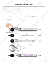
The locomotive and tender lights are controlled by a constant voltage circuit in the
engine. They can be removed and replaced when they burn out by separating the boiler
from the chassis as seen on page 17. Once the boiler has been separated, it will be
necessary to trace the bulb wires back to the circuit boards mounted in the boiler and
unplug the appropriate harness containing the bulb wires.
You can obtain replacement bulbs directly from the M.T.H. Parts Department (order
online: www.mth-railking.com, e-mail: [email protected]; mail: 7020 Columbia
Gateway Drive, Columbia MD 21046-1532, FAX: 410-381-6122).
Headlight and Mars Light
The headlight and the Mars light can be replaced by opening the smokebox front.
Remove the light bulb from the grommet, then unplug the wires. Install the replacement
bulb by reversing the procedure.
Firebox Glow and Cab Interior
To gain access to the firebox glow and cab interior Light bulbs remove the boiler shell
from the chassis as described in the Maintenance Section on page 17.
Lighted Number Boards
To replace the light bulb in the lighted number boards, remove the body from the chassis
as described in the Maintenance Section on page 17. Then remove the power reverse
detail and the feedwater pump detail.
Next remove the 10 screws that attach the belly pan to
the boiler shell and separate the belly pan from the
boiler shell.
Remove the light bulb from the grommet, then unplug
the wires. Install the replacement bulb by reversing
the procedure.
Figure 19:
Light Bulb Replacement Instructions
Figure 17:Headlight & Mars Light
Figure 18
GS-4
GS-2
Cab
Firebox
/