RAB Lighting MD3NTW Operating instructions
- Category
- Decorative lighting
- Type
- Operating instructions

MDLED INSTALLATION INSTRUCTIONS
Thank you for buying RAB lighting xtures. Our goal is to design the best quality products to get the job done right. We’d like to hear your comments.
Call the Marketing Department at 888-RAB-1000 or email: marketing@rabweb.com
TM
IMPORTANT
READ CAREFULLY BEFORE INSTALLING FIXTURE. RETAIN THESE INSTRUCTIONS FOR FUTURE REFERENCE.
RAB xtures must be wired in accordance with the National Electrical Code and all applicable local codes. Proper grounding
is required for safety. THIS PRODUCT MUST BE INSTALLED IN ACCORDANCE WITH THE APPLICABLE INSTALLATION CODE BY A
PERSON FAMILIAR WITH THE CONSTRUCTION AND OPERATION OF THE PRODUCT AND THE HAZARDS INVOLVED.
WARNING: Make certain power is OFF before installing or maintaining xture. No user serviceable parts inside.
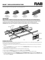
FRAME MOUNTING
For New Construction, mount the Frame before mounting the Housing. This xture can be installed with ceiling temperature not
exceeding 40°C and with minimum plenum height of 7/”.
1. Prepare the mounting surface with appropriate cut out dimension for your unit. Cut-out must be accurate not undersized or
oversized.
2. Insert through C-Channels (sold separately) or other bar stock, in Butter y Brackets and secure accordingly. Consult local
building codes for nal support of xture.
3. Position the frame on C-Channel and secure C-Channel to the Grid as shown in Fig 1.
4. Remove appropriate Knock out on Junction box. Press Clip to open the Junction Box.
5. Feed the supply wires through Knock out hole and connect to the xture wire. See wiring section for details.
6. For di erent ceiling thickness, loosen the Wing Nut and slide the Butter y Bracket. If necessary remove the Wing Nut, insert
and screw in di erent hole provided on the Butter y Bracket (Fig:1). Adjust so that the Frame is ush with the nished ceiling
surface. Tighten the Wing nuts.
Butter y Brackets
MDLED1X
Ceiling Opening :
6/ X 5/”
Female
Connector
Knock Out
Grid
Junction Box
Fig: 1
Wing Nut
MDLED2X
Ceiling Opening :
11/ X 5/”
MDLED3X
Ceiling Opening :
16/ X 5/”
MDLED4X
Ceiling Opening:
21/ X 5/”
C
C
C
C
C-Channel
Clip

MDLED INSTALLATION INSTRUCTIONS
Thank you for buying RAB lighting xtures. Our goal is to design the best quality products to get the job done right. We’d like to hear your comments.
Call the Marketing Department at 888-RAB-1000 or email: marketing@rabweb.com
TM
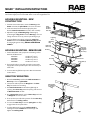
GEAR TRAY MOUNTING
1. Orient the Gear Tray such that the Male connector on
Gear Tray is close to Splice Plate.
2. Connect the tether(s) from the Rough-in to the Gear
Tray for Hands Free mounting.
3. Pull Female Connector conduit through Rough-in
opening. Raise Gear Tray towards opening and connect
to Male Connector conduit.
4. Press Springs Pins inward and slide Gear Tray into holes
on Rough-in one side at a time.
5. There are three possible hole positions for the Gear Tray
with reference to Ceiling surface.
6. To secure the Gear Tray ensure the Spring Pins are fully
engaged into the end plate holes.
7. To adjust LED Head, loosen the Locking Knob by
rotating. Orient the Led Head at desired angle and
tighten the Locking Knob.
Housing
Mounting
Flag
Male Connector
Locking Knob
LED Head
Female
Connector
Gear Tray
HOUSING MOUNTING NEW
CONSTRUCTION
1. For New Construction Units, orient the Housing in the
Frame such that the Splice Plate is closer to connector.
2. Feed connector from Frame through splice plate.
Provided Female connector not used in this assembly.
3. Adjust the length of Mounting Flag of Housing by
positioning the Flag Screw such that Housing is close to
ceiling surface. If necessary, remove part of ag. (Fig 2)
4. To secure xture into ceiling, tighten the Long Flag
Screw from inside the Housing. Mounting Flag should
be snug tight against ceiling. DO NOT OVERTIGHTEN
SCREWS.
Spring Pins (4)
Holes for
adjusting
height of
Gear Tray
}
HOUSING MOUNTING REMODELER
1. For the Remodeler units, prepare the mounting surface
with Cut-o dimensions.
2. The Female Splice is provided separately. Connect the
Supply Wires to the provided splice. Use connectors per
Local code.
3. To secure Housing follow steps 3-4 in New Construction
section above.
Long Flag
Screw
Splice Plate
Frame
(for New
Construc-
tion only)
MDLED1X
Cut-Out : 6/ X 5/”
MDLED2X
Cut-Out: 11/ X 5/”
MDLED3X Cut-Out: 16/ X 5/”
MDLED4X Cut-Out: 21/ X 5/”
Tether
Remove If
Necessary
Fig 2
Fig 3
Female Splice
(provided for
Remodeler
only)

MDLED INSTALLATION INSTRUCTIONS
Thank you for buying RAB lighting xtures. Our goal is to design the best quality products to get the job done right. We’d like to hear your comments.
Call the Marketing Department at 888-RAB-1000 or email: marketing@rabweb.com
TM
TROUBLESHOOTING
1. Check that the line voltage at the xture is correct. Refer
to wiring directions.
2. Is the xture grounded properly?
CLEANING & MAINTENANCE
CAUTION: Be sure xture temperature is cool enough to
touch. Do not clean or maintain while xture is energized.
1. Do not touch or clean the LED. Do not leave LEDs
uncovered.
2. Do not clean any xture surface with wood base cleaning
material such as paper towels or tissues.
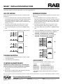
Fig. 6
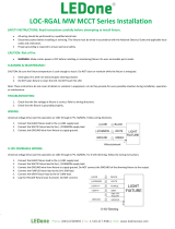
DIMMABLE WIRING
Universal voltage driver permits operation at 120V thru 277V,
50 or 60 Hz.
1. 2x, 3x and 4x xtures can be separately switched. The
black and red xture leads are for two separately switched
circuits. Connect the black xture lead to (+) LINE 1 supply
lead and red xture lead to (+) LINE 2 supply lead. Follow
wiring diagram as in g. 6.
2. For single circuit operation, black and red wires can be
connected together. Follow wiring diagram as in g. 7.
3. Connect the white xture lead to the (-) COMMON supply
lead.
4. Connect the GROUND wire from xture to supply ground.
5. Connect the purple xture lead to the (V+) DIM lead.
CAUTION - Low Voltage Input - 0-10V Max
6. Connect the gray xture lead to the (V-) DIM lead.
CAUTION - Low Voltage Input - 0-10V Max
ONOFF WIRING
Universal voltage driver permits operation at 120V thru 277V,
50 or 60 Hz.
1. 2x, 3x and 4x xtures can be separately switched. The black
and red xture leads are for two separately switched circuits.
Connect the black xture lead to (+) LINE 1 supply lead
and red xture lead to (+) LINE 2 supply lead. Follow wiring
diagram as in g. 4.
2. For single circuit operation, black and red wires can be
connected together. Follow wiring diagram as in g. 5.
3. Connect the white xture lead to the (-) COMMON supply
lead.
4. Connect the GROUND wire from xture to supply ground.
Fig. 4
ACCESSORIES
All accessories available in Black and White colors
SNOOT1* 1/” Door with 20º Lens
SNOOT2 * 2/” Door with 20º Lens
BEZMDLED20 Door Reflector kit with 20º Lens
BEZMDLED30 Door Reflector kit with 30º Lens
BEZMDLED40 Door Reflector kit with 40º Lens
* Note: White Snoot is provided with black insert for glare
reduction.
Easy Installation & Product Help
Tech Help Line
Call our experts 888 RAB-1000
©2014 RAB LIGHTING Inc.
Northvale, New Jersey 07647 USA
rabweb.com
Visit our website for product info
email
Answered promptly sales@rabweb.com
MDLED IN-1014
Fig. 5
Fig. 7
Note: These instructions do not cover all details or variations in equipment nor do they provide for every possible situation during installation, operation
or maintenance.

MDLED INSTALLATION INSTRUCTIONS
Thank you for buying RAB lighting xtures. Our goal is to design the best quality products to get the job done right. We’d like to hear your comments.
Call the Marketing Department at 888-RAB-1000 or email: marketing@rabweb.com
TM
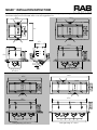
10/”
7/”
6/”
5/”
20/”
23/”
21/”
Ceiling Opening :
6/ X 5/”
Ceiling Opening: 11/ X 5/”
Ceiling Opening: 16/ X 5/”
Ceiling Opening: 21/ X 5/”
5”
5” 5”
5” 5” 5”
15/”
11/”
16/”
/”
2/”
max
/”
-
 1
1
-
 2
2
-
 3
3
-
 4
4


RAB Lighting MD3NTW Operating instructions
- Category
- Decorative lighting
- Type
- Operating instructions
Ask a question and I''ll find the answer in the document
Finding information in a document is now easier with AI
Related papers
-
RAB Lighting ND7TRIMS Operating instructions
-
RAB Lighting LALED78W Operating instructions
-
-
RAB Lighting ENTRA12YW/PCS2 Operating instructions
-
RAB Lighting KLED4R10YYHC Operating instructions
-
RAB Lighting CLED52/BL Operating instructions
-
RAB Lighting HAZXLED80C-DG Operating instructions
-
RAB Lighting PANEL2X2-41N/D10 Operating instructions
-
-
RAB Lighting BOA4P-40D10-40Y-B/LC Operating instructions
Other documents
-
NICOR 14101AR Installation guide
-
-
 LEDone LED Wraparound Shop Light Installation guide
-
RAB RDDLED2S Operating instructions
-
 Commercial Electric CER3GR313BCBP Operating instructions
-
 Ledpax Technology LP4ICLED-6 Installation guide
-
Lightolier IS:46531 User manual
-
Cooper Lighting IMI-699 User manual
-
 LEDone LOC-RGAL MW MCCT Series Installation guide
-
LEDone LWP4 Installation guide


