Wacker Neuson FUE 6/042/200 US User manual
- Type
- User manual

Convertisseur
FUE 5/...
FUE 6/...
FUE-M/S 75A
Converter
Notice d'emploi
Operator's manual
5200006671 08 0811
5200006671
EN-FR

Manufacturer
Wacker Neuson Produktion GmbH & Co. KG
Preußenstraße 41
80809 München
www.wackerneuson.com
Tel.: +49-(0)89-354 02-0
Fax: +49-(0)89-354 02-390
Translation of the original operator's manual in German
0109930en 008
08.2011

1 Foreword
3
1Foreword
This operator's manual contains information and procedures for the safe opera-
tion and maintenance of your Wacker Neuson machine. In the interest of your
own safety and to prevent accidents, you should carefully read through the safety
information, familiarize yourself with it and observe it at all times.
This operator's manual is not a manual for extensive maintenance and repair
work. Such work should be carried out by Wacker Neuson service or authorized
specialists.
The safety of the operator was one of the most important aspects taken into con-
sideration when this machine was designed. Nevertheless, improper use or in-
correct maintenance can pose a risk. Please operate and maintain your Wacker
Neuson machine in accordance with the instructions in this operator's manual.
Your reward will be troublefree operation and a high degree of availability.
Defective machine parts must be replaced immediately!
Please contact your Wacker Neuson representative if you have any questions
concerning operation or maintenance.
All rights reserved, especially reproduction and distribution rights.
Copyright 2011 Wacker Neuson Produktion GmbH & Co. KG
No part of this publication may be reproduced in any form or by any means, elec-
tronic or mechanical, including photocopying, without the expressed written per-
mission of Wacker Neuson.
Any type of reproduction, distribution or storage on data media of any type and
form not authorized by Wacker Neuson represents an infringement of copyright
and will be prosecuted.
We expressly reserve the right to make technical modifications – even without
special notice – which aim at further improving our machines or their safety stan-
dards.

Table Of Contents
4
1. Safety information 5
1.1 General instructions ..............................................................................5
1.2 Operation ...............................................................................................5
1.3 Safety checks ........................................................................................6
1.4 Maintenance ..........................................................................................6
1.5 Transport ...............................................................................................7
1.6 Maintenance checks ..............................................................................7
2. Technical data 8
3. Note 11
3.1 Protective measures in conjunction with electronic inverters ..............11
3.2 Class rating I (grounded conductor) ....................................................11
3.3 Class rating III (protective low voltage) ...............................................12
4. Connecting the inverter 13
4.1 Assembly .............................................................................................13
4.2 Turning on the inverter ........................................................................13
4.3 Turning off the inverter ........................................................................14
4.4 Testing the insulation monitor .............................................................14
5. Operator's controls 14
5.1 FUE 5 and FUE 6/042/200 ..................................................................14
5.2 FUE 6/042/200 US ..............................................................................15
5.3 FUE-M/S 75A ......................................................................................16
6. Malfunctions 17

Safety information
SV00062GB.fm 5
1. Safety information
for electronic frequency and voltage inverters
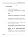
1.1 General instructions
1.1.1 Inverters may only be worked on independently by persons who
∗ are at least 18 years of age,
∗ are physically and mentally fit for this job,
∗ have been instructed in operating inverters and have proved their
abilities to the employer
∗ may be expected to carry out the job they are charged with carefully.
You must have been assigned to work on the inverters by the
company.
1.1.2 Inverters may only be operated according to their intended use, taking
the operator's manual of the manufacturer and this safety information
into account.
1.1.3 The persons charged with the operation of inverters must be made
familiar with the necessary safety measures relating to the machine. In
case of extraordinary uses, the employer shall give the necessary
additional instructions.
1.2 Operation
1.2.1 The function of operation levers (operator's controls) and safety
devices must not be influenced or disabled.
1.2.2 You must ensure that the inverter is only attached to the voltage and
frequency indicated on the rating plate. Choose correct cross section
for extension cord.
1.2.3 Only for FUE 6/042/200 US:
The inverter may only connected and operated with electric power
supplies that have < 30 mA residual current protective devices
(type B).
For all other machines:
The inverter may only be connected to and operated with electric
power supplies that have < 30 mA all-current sensitive residual current
protective devices (type B).

Safety information
SV00062GB.fm 6
1.2.4 Before you start up the inverter, make sure that the machine is in a
vertically stable position to prevent it from tipping over, sliding away or
falling down.
1.2.5 Do not insert or pull out the power plug as a means of turning the
machine on or off. The same applies to the machines to be connected
to the inverter.
1.2.6 The power cable of the inverter must not be used to pull out the plug
from the plug receptacle.
1.2.7 Protect electric cable from heat, oil, and sharp edges.
1.2.8 Electrical equipment and material may only be used if they comply with
operational and local safety requirements. They must be in proper
condition and this condition is to be maintained.
1.2.9 Do not operate the inverter in areas where explosions may occur.
1.3 Safety checks
1.3.1 Before starting operation, the operator has to check that all control and
safety devices are functioning properly.
1.3.2 Check electric cables for damage on a regular basis.
1.3.3 Inverters may only be operated with all safety devices installed.
1.3.4 If defects on the safety devices or other defects impairing the
operational safety of machine are observed, the supervisor must be
informed immediately.
1.3.5 If there are defects jeopardizing operational safety, the machine has to
be switched off immediately.
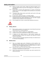
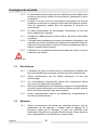
1.4 Maintenance
1.4.1 Only use original spare parts. Alterations to this machine, incl.
adjustments of the frequency set by the manufacturer may only be
carried out with the express permission of Wacker Neuson. In case of
non-observance, all liability shall be refused.
1.4.2 Disconnect the inverter from the electrical power supply system before
carrying out maintenance and repair work.
1.4.3 Work on the electric parts of the machine may only be carried out by
skilled technicians.
Dan
g
er to life

Safety information
SV00062GB.fm 7
1.4.4 The green-yellow grounded conductor of the connecting cable must be
longer so that it will not be torn off if the strain relief fails. If interrupted,
it can cause fatal injury. After conducting repairs, check the grounded
conductor for continuity.
1.4.5 As soon as maintenance and repair jobs have been completed, all
safety devices must be properly reinstalled.
1.4.6 Do not clean the machine with a high pressure washer.
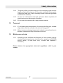
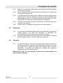
1.5 Transport
1.5.1 For the loading and transportation of inverters with lifting gear, suitable
sling chains must be secured at the relevant fixing point.
1.5.2 When inverters are being transported in vehicles, precautions have to
be taken to ensure that they do not slip or fall over.
1.6 Maintenance checks
1.6.1 According to the conditions and frequency of use, inverters must be
checked for safe operation by a technician, for example at a WACKER
service station, at least once every 6 months and repaired if
necessary.
Please observe the appropriate rules and regulations valid in your
country.

Technical data
TD00722GB.fm 8
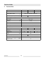
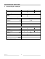
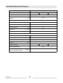
2. Technical data
FUE 5/042/200 FUE 5/115/200 FUE 5/250/200
Item no. 0008901 0008948 0008947
Length x Width x Height
mm
(in):
520 x 310 x 493,5 (20.5 x 12.2 x 19.4)
Operating weight (mass) kg (lb): 29,5 (65) 32 (70.5)
Power supply value (input)
Input voltage V: 400 - 415 3~
Frequency Hz: 50 - 60
Input current A: 8
Power kVA: 5,5
Connecting cable 2,5 m with 16A CEE plug
Delivery (output)
Output voltage V: 42 3~ 115 3~ 250 3~
Frequency Hz:
200
Output current A: 52 20 9
Power kVA:
3,8
Number of plug receptacles
3 CEE 32A 3 CEE 16A
Protection class IP 44
Sound pressure level (L
PA
) at
operator's station
dB(A):
70

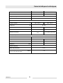
Technical data
TD00722GB.fm 9
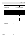
FUE 6/042/200 FUE 6/042/200 US
Item no. 0610094 0610015
Length x Width x Height
mm
(in):
520 x 310 x 493.5 (20.5 x 12.2 x 19.4)
Operating weight (mass) kg (lb): 29,5 (65)
Power supply value (input)
Input voltage V: 400 - 415 3~ 230 - 240 1~
Frequency Hz: 50 - 60
Input current A: 13 22
Power kVA: 9 5,2
Connecting cable
2,5m with 16A CEE-
plug
10 m without CEE-plug
Delivery (output)
Output voltage V: 42 3~
Frequency Hz:
200 0 - 200
Output current A: 60 52
Power kVA:
4,4 3,8
Number of plug receptacles
3 CEE 32A
Protection class IP 44
Sound pressure level (L
PA
) at
operator's station
dB(A):
70

Technical data
TD00722GB.fm 10
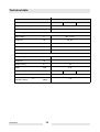
FUE-M/S 75A
Item no. 0107999 0108000 0610194
Length x Width x Height mm (in): 520 x 310 x 493.5 (20.5 x 12.2 x 19.4)
Operating weight (mass) kg (lb): 29.5 (65)
Power supply value (input)
Input voltage V: 400 - 415 3~
Frequency Hz: 50 - 60
Input current A: 13
Power kVA: 9
Connecting cable 2.5 m with 16 A CEE plug
Delivery (output)
Output voltage V: 42 3~
Frequency Hz:
0 - 200
Output current A: 75
Power kVA:
5.45
Number of plug receptacles
4 CEE 32 A 2 CEE 63 A 6 CEE 32 A
Protection class IP 44
Sound pressure level (L
PA
) at
operator's station
dB(A):
< 70

Note
T00871GB.fm 11
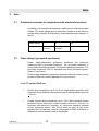
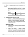
3. Note
3.1 Protective measures in conjunction with electronic inverters
In addition to the protective measures, machines are divided into class
ratings. The class ratings specify protective measures to be taken to
prevent direct contact. A distinction is made between class ratings I, II
and III.
3.2 Class rating I (grounded conductor)
Power supply-dependent protective measures are protective
measures with a grounded conductor. The grounded conductor is
connected to the inactive bodies of electrical operating equipment. The
grounded conductor (PE) for insulated lines must be marked green-
yellow in its entirety.
Power supply-dependent protective measures shut off excess current
protective devices located upstream if an error occurs.
In the TT-net and TN-S-net:
∗ Protect plug receptacles up to 16 A for single-phase operation with
residual current protective devices that have a rated residual current of
< 30 mA.
∗ Protect 3-phase plug receptacles up to < 32 A with a residual current
protective device that have a rated residual current of < 30 mA. For
operation with electronic inverters, an "all-current sensitive residual
current protective device" with 30 mA must be used. If this is not
possible due to high stray currents (contingent on EMC line filters), a
differential current monitor must be employed.
Class rating I II III
Designation Grounded
conductor
Protective
insulation
Protective low voltage

Note
T00871GB.fm 12
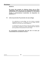
Caution:
Due to the high stray current levels of the interference filter,
make sure that the inverter is only connected to one fault
current protective switch. This will prevent the fault current
protective switch from being triggered inadvertently.
3.3 Class rating III (protective low voltage)
Protective low voltage are rated voltages up to 50 V of AC current. The
protective low voltage prevents the build-up of a dangerous contact
voltage.
Safety transformers are permitted for generating protective low
voltages for which the low-voltage side has no conductive connection
to the power supplying network.
The inverter must be grounded with the grounded conductor
connection!

T01066GB.fm 13
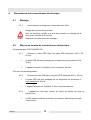
4. Connecting the inverter
4.1 Assembly
4.1.1 Assembly instructions for the version without plug receptacle
Danger of electrocution!
Only a qualified electrician is permitted to assemble the plug and
perform a safety check.
Observe the assembly instructions!
4.2 Turning on the inverter
Only for FUE 6/042/200 US:
4.2.1 Plug the CEE plug into a suitable CEE plug receptacle (230 V, 50/
60 Hz).
∗ The CEE plug receptacle must be fuse protected with a 30 mA fault
current protective switch.
∗ The machine requires 1 phase and a grounded conductor.
For all other machines:
4.2.2 Plug the CEE plug into a suitable CEE plug receptacle (400 V, 50 Hz).
∗ The CEE plug receptacle must be fuse protected with an all-current
sensitive 30 mA fault current protective switch.
∗ The machine requires 3 phases and a grounded conductor.
4.2.3 The machine is turned on with the green On button.
∗ The white LED lights up when the inverter is ready for operation.
∗ If the green LED lights up, the temperature of the installed transformer
is OK, and the voltage is output at the plug receptacles (a soft
humming sound can be heard).
Danger to life

T01066GB.fm 14
4.3 Turning off the inverter
The machine is turned off with the red Off button.
∗ Both LEDs go out.
4.4 Testing the insulation monitor
Only FUE 5/115/200 and FUE 5/250/200:
The function of the insulation monitor can be tested with the touch
button with control lamp:
∗ The machine must turn off when the touch button with control lamp is
pressed.
∗ The green LED goes out.
5. Operator's controls
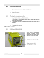
5.1 FUE 5 and FUE 6/042/200
Power cable with 16 A
CEE plug 400 V, 50 Hz
On/Off button with white LED
Green LED for temperature
indicator. Insulation monitor
touch button with control lamp
(only FUE 5/115, FUE 5/250)

T01066GB.fm 15
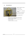
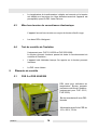
5.2 FUE 6/042/200 US
∗ Switched to the left: to operate the AR (external vibrator)
- Frequency controller is activated
∗ Switched to the right: to operate the IR (internal vibrator)
- Frequency of 200 Hz
- Frequency controller is not activated
Power cable for 230 V
On/Off button with white LED
Switch * for internal vibrator /
external vibrator
Green LED for temperature
indicator
Frequency controller
Reset button with red LED

T01066GB.fm 16
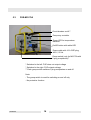
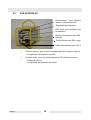
5.3 FUE-M/S 75A
* Switched to the left: FUE does not output voltage
* Switched to the right: FUE outputs voltage
** Each group switch switches 3 plug receptacles on and off
Note:
- The group switch is used for switching on and off only
- No protective function
Frequency controller
Green LED for temperature
indicator
On/Off button with white LED
Power cable with 16 A CEE plug
400 V, 50 Hz
Circuit breaker on/off *
Group switch (only for M/S 75A with
6 plug receptacles)**

T01066GB.fm 17
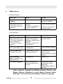
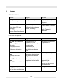
6. Malfunctions
FUE 6/042/200 US
For all machines:
1
Have machine repaired by Wacker Neuson Service, your
Wacker Neuson subsidiary or your Wacker Neuson dealer.
Addresses can be found on the Wacker Neuson homepage.
Malfunction Cause Remedy
Vibrators are not
working
* Frequency is too low * Increase frequency via
frequency controller
FUE does not work
* Both LEDs are not lit
* Red LED in the reset
button is lit
* Frequency converter is
defective
* Current consumption is
too high, overload
* Have machine repaired
1
* Press the reset button,
machine restarts
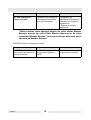
Malfunction Cause Remedy
FUE does not work
None of the LEDs are lit
* CEE plug is plugged in
to the receptacle,
* There is no voltage
present
* Fault current protective
switch in the worksite
switchgear assembly was
triggered
* Inverter module in the
FUE defective
Reset the fault current
protective switch
FUE does not work
None of the LEDs are lit
* Inverter module in the
FUE defective
* Have machine repaired
1
FUE does not work
* Green LED is not lit
* Transformer is too hot
and has switched off
* Allow machine to cool
down in the air
* Only use air as a cooling
medium
FUE is working
White or green or both
LEDs are not lit
LED defective Replace LED
FUE starts sluggishly Power demand of the
connected machines is
too high
* Observe the power
specifications on the
rating plate,
* Reduce the number of
machines

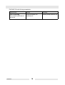
T01066GB.fm 18
FUE M/S 75A with 6 plug receptacles
Malfunction Cause Remedy
FUE is working
Connected machines do
not work
Group switches are
switched off
Switch group switches on

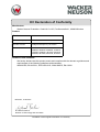
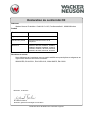
Translation of the original Declaration of Conformity
EC Declaration of Conformity
Manufacturer
Wacker Neuson Produktion GmbH & Co. KG, Preußenstraße 41, 80809 München
Product
Guidelines and standards
We hereby declare that this product meets and complies with the relevant regulations and
requirements of the following guidelines and standards:
2006/95/EG, EN 61558-1, EN 61558-2-23, 2004/108/EG, EN 61000
Product
FUE
Product category Inverter
Product function Voltage and frequency conversion
Item number 0007978, 0007979, 0008901, 0008947,
0008948, 0008949, 0008950, 0108479,
0107999, 0108000, 0610015, 0610019,
0610020, 0610094, 0610156, 0610194
Dr. Michael Fischer
Director of Technology and Innovation
München, 01.08.2011
Page is loading ...

Convertisseur
FUE 5/...
FUE 6/...
FUE-M/S 75A
Notice d'emploi
Page is loading ...
Page is loading ...
Page is loading ...
Page is loading ...
Page is loading ...
Page is loading ...
Page is loading ...
Page is loading ...
Page is loading ...
Page is loading ...
Page is loading ...
Page is loading ...
Page is loading ...
Page is loading ...
Page is loading ...
Page is loading ...
Page is loading ...
Page is loading ...
Page is loading ...
Page is loading ...
Page is loading ...
-
 1
1
-
 2
2
-
 3
3
-
 4
4
-
 5
5
-
 6
6
-
 7
7
-
 8
8
-
 9
9
-
 10
10
-
 11
11
-
 12
12
-
 13
13
-
 14
14
-
 15
15
-
 16
16
-
 17
17
-
 18
18
-
 19
19
-
 20
20
-
 21
21
-
 22
22
-
 23
23
-
 24
24
-
 25
25
-
 26
26
-
 27
27
-
 28
28
-
 29
29
-
 30
30
-
 31
31
-
 32
32
-
 33
33
-
 34
34
-
 35
35
-
 36
36
-
 37
37
-
 38
38
-
 39
39
-
 40
40
-
 41
41
-
 42
42


Wacker Neuson FUE 6/042/200 US User manual
- Type
- User manual
Ask a question and I''ll find the answer in the document
Finding information in a document is now easier with AI
in other languages
Related papers
-
Wacker Neuson FUE 5/115/200 User manual
-
Wacker Neuson FUE M/S 75A 6CEE-32A User manual
-
Wacker Neuson FUE 6/042/200 US User manual
-
-
-
-
-
-
Wacker Neuson PAR 27/2 User manual
-