Page is loading ...

valves.emerson.com VCIOM-03107-EN 17/05
Before installation these instructions must be read fully and understood
© 2017 Emerson. All Rights Reserved.
VAREC SERIES 220 ROOF MANWAY COVER
InstallatIon, operatIon and maIntenance InstructIons
LIMITATIONS OF SELLER'S LIABILITY
If it is determined that this instruction
manual created some new warranties,
Emerson's liability shall be limited to repair
or replacement under the standard warranty
clause. In no case shall Emerson's liability
exceed that stated as Limitations of Remedy
in the contract between Emerson and the
customer.
SAFETY PRECAUTIONS
Read and understand this instruction manual
before installing, operating or performing
maintenance on Varec Series 220 roof manway
covers. Follow all precautions and warnings noted
herein when installing, operating or performing
maintenance on this equipment.
WARNING
• Wear appropriate gloves and/or breathing
apparatus if hazardous vapors are present.
• Allow any pressure to vent slowly when opening
cover by carefully backing off the wing nut.
DISCLAIMER OF WARRANTIES
The contract between the seller and the buyer
states the entire obligation of the seller. The
contents of this instruction manual shall not
become part of or modify any prior or existing
agreement, commitment or relationship
between the seller and buyer. There are no
express or implied warranties set out in this
instruction manual. The only warranties that
apply are those in the existing contract between
the seller and buyer.
The Varec Series 220 roof manway cover has
not been tested under all possible operational
conditions and Emerson does not have all the
data relative to your application. The information
in this instruction manual is not all inclusive
and does not and can not take into account all
unique situations. Consequently, you should
review this product literature in view of your
application. If you have any further questions,
please contact Emerson for assistance.
Safety precaution definitions:
CAUTION
Damage to equipment may result if this
precaution is disregarded.
WARNING
Direct injury to personnel or damage to
equipment which can cause injury to personnel
may result if this precaution is not followed.
GENERAL
The Series 220 manway covers or entrance
hatch covers are designed for use on low
pressure tank roofs or digester covers to
provide quick and easy physical access.
CONSTRUCTION
Manhole covers are constructed of a heavy
cast base and cover. The cover is hinged and
is locked in the closed position by wing nuts.
Twoconfigurations are provided. The 18 inch
and 20 inch models have a rigid center beam.
The 24 inch through 36 inch models have
multiple hinged lugs. Working pressure rating
is 1 psig (6.9 kPa).
For material selection, see Figures 1 and 2.
33-07764 Rev C

2
VAREC SERIES 220 ROOF MANWAY COVER
InstallatIon, operatIon and maIntenance InstructIons
OPERATION
1. To close and seal manhole cover,
lowercover onto base.
CAUTION
Do not drop cover onto base. Always control
lowering so insert and seating surface are not
damaged.
2. Swing yokes and wing nuts into slot of beam
or lugs.
a. For 18 inch and 20 inch models, tighten
single wing nut until unit is sealed.
b. For 24 inch through 36 inch models,
first tighten wing nuts finger tight.
Thentighten one-half turn each, working
around cover until unit is sealed.
CAUTION
Do not over tighten. Do not use wrench or any
other hand tool.
3. To open, loosen all wing nuts and swing
wing nut and yoke out of slots.
WARNING
• Allow any pressure to vent slowly when opening
cover by carefully backing off wing nuts.
• Wear appropriate gloves and/or breathing
apparatus if hazardous vapors are present.
4. Lift cover off base. Swing away and control
lowering to full open position.
INSTALLATION
1. The tank roof or digester cover must have
the appropriate flange installed for mating
with the manhole cover. See reference
drawing for drilling pattern. Locate
mounting flange with clearance for cover in
open position.
2. Remove manhole cover from shipping
container. Inspect cover, insert and seating
surface of base to verify surface is smooth
and unit will seat and seal properly. Verify
that all components are operable such as
wing nuts, yoke, hinge etc.
MAINTENANCE
Periodically inspect for freeness of operation.
Check wing nut and yoke threads. Check insert
and seating surface for wear or damage. Check
flange bolts and nuts for tightness.
The insert may be replaced if damaged.
Remove old insert and wipe groove clean.
Cut new insert 1" to 2" longer than old insert.
Work new insert into groove with flat board
and rubber mallet until seated. Trim overlap
so ends butt and close gap completely. Ensure
that the gasket is installed properly and seals
against the base seating surface.
REPLACEMENT PARTS
When ordering replacement parts, specify
manhole cover by model number and size.
Identify replacement parts by item number,
description and material as shown on reference
drawings. Include part numbers wherever
possible.
REFERENCE DRAWINGS
C2121- 18" and 20" Series 220 manway cover
C2118- 24" - 36" Series 220 manway cover.
3. Orient the unit so the cover will have
clearance in the open position. Install as
follows:
a. For manholes with drilled bases: place a
suitable gasket on the mounting flange.
Place the manhole assembly on the
gasket. Install mounting hardware and
tighten uniformly.
b. For manholes with weld-type bases:
weld base to tank roof or adapter (by
others) using compatible welding rod.
Weld all around with a leak tight joint.
WARNING
Ensure that there are no combustible vapors in
the tank or atmosphere before welding.
Size code 18 20 24 30 36
Nominal pipe size inch (mm)
18 (450) 20 (500) 24 (600) 30 (750) 36 (900)
Insert, tallow treated flax 11408070 11408075 11408077 11408079 11408080
(
5
/
8" SQ X 64.5") (
5
/
8" SQ x 72.5") (
3
/
4" SQ x 78.0") (
3
/
4" SQ x 98.0") (
3
/
4" SQ x 117.0")
Wing nut A1441-004 A1441-004 A1441-004 A1441-004 A1441-004
Yoke B1117-004 B1117-004 B1117-004 B1117-004 B1117-004
Hinge pin B4318-105 B4318-205 B11886-105 B11886-305 B11886-505
Lug pin B11887-105 B11887-105 B11887-105 B11887-105 B11887-105

3
AA
1
5
9
7
8
13
11
12
2
4
3
10
6
B
øA
øF
øC (B.C.)
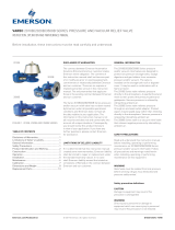
18 23 (584) 7⅞ (200) 21¼ (540) 28
9
/
16 (14) 17¾ (451)
20 26 (660) 8 (203) 23¼ (591) 32
9
/
16 (14) 19⅞ (505)
VAREC SERIES 220 ROOF MANWAY COVER
InstallatIon, operatIon and maIntenance InstructIons
Aluminum, iron or 316 stainless steel base - drilled
Steel base - for welding (undrilled)
FIGURE 1
SIZES 18" AND 20"
D (no. of holes) equally spaced - straddle centerline
E (diameter of holes)
3
/
4" (19 mm)
SECTION A - A
MATERIAL TABLE
Standard material
Item Description Series 220XX11 Series 220XX22 Series 220XX32 Series 220XX66
1 Base Aluminum Iron Steel 316 Stainless steel
2 Cover Aluminum Iron Iron 316 Stainless steel
3 Yoke Brass Brass Brass 316 Stainless steel
4 Wing nut Brass Brass Brass 316 Stainless steel
5 Hinge pin 304 Stainless steel 304 Stainless steel 304 Stainless steel 304 Stainless steel
6 Lug pin 304 Stainless steel 304 Stainless steel 304 Stainless steel 304 Stainless steel
7 Insert Braided flax Braided flax Braided flax Braided flax
8 Beam Steel Steel Steel 316 Stainless steel
9 Cotter pin 316 Stainless steel 316 Stainless steel 316 Stainless steel 316 Stainless steel
10 Cotter pin 316 Stainless steel 316 Stainless steel 316 Stainless steel 316 Stainless steel
11 Hex head cap screw Zinc plated steel Zinc plated steel Zinc plated steel 316 Stainless steel
12 Hex nut Zinc plated steel Zinc plated steel Zinc plated steel 316 Stainless steel
13 Washer Zinc plated steel Zinc plated steel Zinc plated steel 316 Stainless steel
SIZE AND DIMENSIONS
Inch (mm)
Size A B C D E F

4
AA
4
3
6
9
2
7
81
5
B
øA
øF
øC (B.C.)
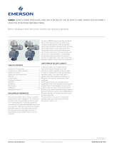
24 33¼ (845) 6⅛ (156) 30¼ (768)
30 36½ (927) 6⅛ (156) 33¾ (857)
36 45½ (1156) 6½ (165) 42¼ (1073)
24 28
11
/
16 (17) 24 (610)
30 36
11
/
16 (17) 30¼ (768)
36 42 ⅞ (22) 35
13
/
16 (910)
VAREC SERIES 220 ROOF MANWAY COVER
InstallatIon, operatIon and maIntenance InstructIons
Aluminum, iron or 316 stainless steel base - drilled
Steel base - for welding (undrilled)
SIZE AND DIMENSIONS
Inch (mm)
Size A B C
FIGURE 2
SIZES 24", 30" AND 36"
SECTION A - A
D (no. of holes) equally spaced
E (diameter of holes)
24" size, holes straddle centerline
30" and 36" sizes, holes on centerline
24" size as shown, 3 lugs
30" and 36" sizes, 4 lugs straddle centerline
3
/
4" (19 mm)
MATERIAL TABLE
Standard material
Item Description Series 220XX11 Series 220XX22 Series 220XX32* Series 220XX66
1 Base Aluminum Iron Steel 316 Stainless steel
2 Cover Aluminum Iron Iron 316 Stainless steel
3 Yoke Brass Brass Brass 316 Stainless steel
4 Wing nut Brass Brass Brass 316 Stainless steel
5 Hinge pin 304 Stainless steel 304 Stainless steel 304 Stainless steel 304 Stainless steel
6 Lug pin 304 Stainless steel 304 Stainless steel 304 Stainless steel 304 Stainless steel
7 Insert Braided flax Braided flax Braided flax Braided flax
8 Cotter pin 316 Stainless steel 316 Stainless steel 316 Stainless steel 316 Stainless steel
9 Cotter pin 316 Stainless steel 316 Stainless steel 316 Stainless steel 316 Stainless steel
* Not available for 36"
Size D E F
/