ALBI 4 - VERTICAL POST MIX DISPENSER
Installation Manual
Original instructions
English version – EN
Spanish – ESP
French – FR
German – DE
Italian – IT
Chinese - CHN
Danish - DK
Finnish - FN
PART No. PI015616
REVISION: No. 5
ISSUE DATE: 7/02/2019
Patent Applied For
WO2017/077295
Appliance types covered:
Model Description Voltage / Frequency
14-2000-01 Albi 4 – All Carbonated Products 230V / 50Hz
14-2000-02 Albi 4 – All still products 230V / 50Hz
14-2000-03 Albi 4 – Still and Carbonated products 230V / 50Hz
14-2000-05 Albi Aqua – Remote Cooler, Carbonator 230V / 50Hz
14-2001-01 Albi 4 – All Carbonated Products (Non UL) 110V / 60Hz
14-2001-02 Albi 4 – All still products (Non UL) 110V / 60Hz
14-2001-03 Albi 4 – Still and Carbonated products (Non UL) 110V / 60Hz
14-2001-05 Albi Aqua – Remote Cooler, Carbonator (Non UL) 110V / 60Hz
14-2002-01 Albi 4 – All Carbonated Products 220V / 60Hz
14-2002-03 Albi 4 – Still and Carbonated products 220V / 60Hz
14-2003-01 Albi 4 – All Carbonated Products (UL Version) 110V / 60Hz
14-2003-05 Albi Aqua – Remote Cooler, Carbonator (UL Version) 110V / 60Hz
14-2004-01 Albi Flex Plus - Still and Carbonated products 230V / 50 Hz

2
Dear Customer
Please read the User Guide and Installation Manual carefully before
operating this unit.
Please keep the User Guide and Installation safe and with the unit.
Examine the equipment immediately after supply for transport damage. Contact
your equipment supplier and/or carrier if necessary. Damage, which arises by
inappropriate treatment or operation, is not subject to guarantee \ warranty.
Equipment manufactured or supplied by Welbilt (Halesowen) Limited complies
with the current legislation and standards of the EU and represents the current
standard of technology. Safety during operation may only be assured by following
the instructions in this guide.
Reproduction of any kind without previously written permission of Welbilt
(Halesowen) Limited is prohibited.
Welbilt (Halesowen) Limited typically designs for a 5-10 year product lifetime
dependent upon the type of equipment.
Installation Manual

3
Table of Contents
Section 1 – Warnings 4-8
Section 2 – General description and function of the unit 9
Section 3 – Installation & Commissioning of the unit 10-34
Section 4 – Maintenance and cleaning 35-45
Section 5 – Spare parts list 46-56
Section 6 – Fault nding charts 57-61
Section 7 – Technical Specication 62-63
Section 8 – Declaration of conformity 64-65

4
Section 1
SECTION 1 – WARNINGS
WARNING: THIS APPLIANCE CAN BE USED BY CHILDREN AGED FROM 8 YEARS
AND ABOVE AND PERSONS WITH REDUCED PHYSICAL, SENSORY OR
MENTAL CAPABILITIES OR LACK OF EXPERIENCE AND KNOWLEDGE
IF THEY HAVE BEEN GIVEN SUPERVISION OR INSTRUCTION
CONCERNING USE OF THE APPLIANCE IN A SAFE WAY AND
UNDERSTAND THE HAZARDS INVOLVED. CHILDREN SHALL NOT PLAY
WITH THE APPLIANCE. CLEANING AND USER MAINTENANCE SHALL
NOT BE MADE BY CHILDREN WITHOUT SUPERVISION.
WARNING: THERE ARE NO END USER SERVICEABLE PARTS. ANY FAULT OR
PROBLEM WITH THE EQUIPMENT MUST ONLY BE RECTIFIED BY A
QUALIFIED SERVICE ENGINEER.
WARNING: ALTHOUGH EVERY CARE IS TAKEN DURING MANUFACTURE, DAMAGE
TO THE METALWORK DURING TRANSPORT, INSTALLATION AND
GENERAL USE MAY OCCUR. THIS MAY RESULT IN SHARP OR JAGGED
EDGES. AVOID CONTACT WITH METAL EDGES OR OTHER POTENTIAL
HAZARDS.
WARNING: PLEASE REFER TO MANUAL HANDLING GUIDELINES WHEN LIFTING
THIS EQUIPMENT.
BEFORE LIFTING OR MOVING THIS EQUIPMENT IT IS RECOMMENDED
THAT ALL PERSONS PERFORMING THESE TASKS SHOULD RECEIVE
RELEVANT TRAINING IN SAFE HANDLING.
ALL PERSONS LIFTING OR MOVING THIS EQUIPMENT MUST BE
WEARING THE CORRECT PERSONAL PROTECTIVE EQUIPMENT.

55
Section 1
TO PREVENT PERSONAL INJURY WHERE PRACTICAL, TRANSPORTING
OF THE UNIT OVER EXTENDED DISTANCES SHOULD BE DONE USING
A MECHANICAL AID.
WHEN NOT USING A MECHANICAL AID, WELBILT RECOMMEND A
2 MAN LIFT.
ALWAYS TRANSPORT THE UNIT IN THE CORRECT UPRIGHT POSITION,
NEVER ON ITS SIDE OR TOP.
WARNING: IT IS UNSAFE TO LIFT OR ATTEMPT TO MOVE THE APPLIANCE DURING
CLEANING OR AT ANY OTHER TIME WHEN THE UNIT IS OPERATING.
WARNING: ONLY USE EQUIPMENT FOR ITS INTENDED USE AS DESCRIBED IN
THE INSTALLATION MANUAL. THERE ARE NO OTHER RECOMMENDED
USES FOR THIS EQUIPMENT. UNINTENDED USE OF THE EQUIPMENT
WILL INVALIDATE YOUR WARRANTY.
WARNING: WELBILT (HALESOWEN) LIMITED HAS DONE A COMPLETE QUALITY
AND FUNCTION CHECK ON EACH UNIT. NEVERTHELESS, LEAKAGES
ON WATER LINES DURING OPERATION CAN NOT BE EXCLUDED
TOTALLY. REGULARLY INSPECT THE EQUIPMENT FOR SIGNS OF
LEAKAGE.
WARNING: CARE MUST BE TAKEN WHEN HANDLING THIS EQUIPMENT TO AVOID
EITHER DAMAGING THE REFRIGERATION TUBING OR INCREASING
THE RISK OF A LEAK.
WARNING: COMPONENT PARTS SHALL BE REPLACED WITH LIKE COMPONENTS
AND SERVICING SHALL BE DONE BY FACTORY AUTHORIZED SERVICE
PERSONNEL, SO AS TO MINIMIZE THE RISK OF POSSIBLE IGNITION
DUE TO INCORRECT PARTS OR IMPROPER SERVICE.
WARNING: KEEP ALL VENTILATION OPENINGS IN THE APPLIANCE CLEAR OF
OBSTRUCTION
WARNING: DO NOT USE MECHANICAL DEVICES OR OTHER MEANS TO
ACCELERATE THE DEFROSTING PROCESS, OTHER THAN THOSE
RECOMMENDED BY THE MANUFACTURER.
WARNING: THE EVAPORATION TEMPERATURE IN THE REFRIGERATION CIRCUIT
CAN TYPICALLY BE -10°C. WITHOUT TAKING PREVENTATIVE STEPS
THIS CAN BE A POTENTIAL SOURCE OF INJURY.
WARNING: THE COMPRESSOR, CONDENSER, HIGH PRESSURE REFRIGERATION
TUBES AND MOTORS WILL BECOME HOT DURING OPERATION.
CONTACT WITH THESE PARTS DURING OPERATION SHOULD BE
AVOIDED.

6
Section 1
WARNING: DO NOT DISPOSE OF THE UNIT WITHOUT FIRST REMOVING ALL R290
REFRIGERANT. THIS PROCESS CAN ONLY BE PERFORMED BY AN
ENGINEER QUALIFIED TO HANDLE HYDROCARBON REFRIGERANTS.
WARNING: ALL UNITS ARE FITTED WITH A STANDARD EURO PLUG TO IEC83:1985
OR A UK PLUG OR COUNTRY SPECIFIC PLUG. BEFORE COMMENCING
ANY CLEANING ISOLATE THE UNIT BY:
1. SWITCH OFF THE SOCKET THAT THE PLUG IS INSTALLED INTO.
2. REMOVE THE PLUG FROM THE SOCKET.
ALL INSTALLATIONS MUST BE CHECKED THAT THEY MEET LOCAL
ELECTRICAL REGULATIONS AND NATIONAL CODES BEFORE THE
APPLIANCE IS TURNED ON.
WARNING: IF THE MAINS LEAD FITTED TO THIS EQUIPMENT IS IN ANY WAY
DAMAGED IT MUST BE REPLACED BY WELBILT (HALESOWEN) LIMITED,
OUR SERVICE AGENT OR A QUALIFIED ELECTRICAL ENGINEER. THE
MAINS LEAD CONNECTION IS A ‘Y’ TYPE.
WARNING: THIS EQUIPMENT MUST BE EARTHED.
THIS EQUIPMENT IS CHARGED WITH R290 REFRIGERANT (PROPANE).
ONLY QUALIFIED SERVICE ENGINEERS HOLDING A VALID HANDLING CERTIFICATE FOR
CARE 40 (PROPANE) CAN WORK ON THE REFRIGERATION SYSTEM OF THIS EQUIPMENT.
PLEASE READ THE INFORMATION BELOW BEFORE ANY WORK IS CARRIED OUT.
Refrigeration R290 (Care 40, Propane)
Note: Only engineers who have been trained in the safe handling and
use of hydrocarbon refrigerants should work on this system.
• Work on this system in a wall ventilated area or outside.
• Use a local leak detector to indicate if there is hydrocarbon
in the air around the system (place it at a low level as HCs are
heavier than air)
•Ensuretherearenosourcesofignition(amesorsparking
electrical components) within 3m (10 feet) of your work area.
• If replacing components use like for like replacements.
• Take great care when brazing to ensure all HC has been
removed from the system.
Use refrigerant grade propane (R290 or Care 40)
Warning

77
Section 1
WARNING: THE CARBONATOR IS AN INTEGRAL PART OF THE UNIT AND IT
SHOULD BE NOTED THAT THE CARBONATION PROCESS INVOLVES
THE USE OF HIGH PRESSURE AND POTENTIALLY NOXIOUS GAS. AS
SUCH SUE CARE MUST BE TAKEN WHEN USING THE EQUIPMENT.
WARNING: CARBON DIOXIDE LEAKS ARE POTENTIALLY FATAL IF
CONCENTRATIONS RISE TO A DANGEROUS LEVEL. IN VIEW OF
THIS THE INSTALLATION SHOULD BE REGULARLY CHECKED FOR
INTEGRITY AND THE GENERAL AREA OF INSTALLATION PROPERLY
VENTILATED AT ALL TIMES.
IT IS RECOMMENDED THAT A CO2 LEAK DETECTOR IS FITTED IN THE
VICINITY OF THE EQUIPMENT.
THE UNIT SHOULD NOT BE INSTALLED IN A ROOM WHERE SHOULD
THE CONTENTS OF THE CO2 BOTTLE BE EVACUATED INTO THE
ROOM, CO2 LEVELS WOULD REACH LETHAL LEVELS.
WELBILT RECOMMEND THAT ONLY 5 OR 7 KG CO2 CYLINDERS BE
USED WITH THE ALBI APPLIANCE.
THE CARBON DIOXIDE CONCENTRATION IN A ROOM AFTER A TIME -
T - CAN BE CALCULATED AS.
C = (Q / N V) [1 - (1 / EN T)] + (C0 - CI) (1 / EN T) + CI (1).
WHERE:
C = CARBON DIOXIDE CONCENTRATION IN THE ROOM (M3/M3)
Q = CARBON DIOXIDE SUPPLIED TO THE ROOM (M3/H
V = VOLUME OF THE ROOM (M3)
E = THE CONSTANT 2.718
N = NUMBER OF AIR SHIFTS PER HOUR (1/H)
T = TIME (HOUR, H)
CI = CARBON DIOXIDE CONCENTRATION IN THE INLET VENTILATION
AIR (M3/M3)
C0 = CARBON DIOXIDE CONCENTRATION IN THE ROOM AT START,
T = 0 (M3/M3)
THE VENTILATION IN THE ROOM WHERE THE UNIT IS INSTALLED
SHOULD NOT ALLOW THE CO2 CONCENTRATION TO EXCEED
5000PPM WORK PLACE 8 HOUR EXPOSURE LIMIT.
BEFORE INSTALLATION A WORK PLACE RISK ASSESSMENT MUST BE
PERFORMED CONSIDERING THE RISK ASSOCIATED WITH THE USE OF
CO2.

8
Section 1
CO2 CYLINDER SAFETY INFORMATION
WARNING: IN ORDER TO COMPLY WITH UK WATER REGULATIONS A WRAS
APPROVED DOUBLE NON RETURN VALVE MUST BE INSTALLED ON
THE INCOMING MAINS WATER SUPPLY BEFORE THE APPLIANCE IN THE
SYSTEM.
FOR INSTALLATION OF EQUIPMENT ACROSS EUROPE A CLASS 3
PROTECTIVE DEVICE AS DEFINED BY EN1717, APPROVED FOR THE
COUNTRY OF INSTALLATION MUST BE INSTALLED ON THE INCOMING
MAINS WATER SUPPLY BEFORE THE APPLIANCE IN THE SYSTEM.
WARNING: DO NOT DISPOSE OF THIS EQUIPMENT AS UNSORTED MUNICIPAL
WASTE, CONTACT YOUR DISTRIBUTOR OR SERVICE AGENT FOR THE
COLLECTION AND SAFE DISPOSAL OF THIS EQUIPMENT. WELBILT
(HALESOWEN) LTD. IS A REGISTERED MEMBER OF A WEEE PRODUCER
COMPLIANCE SCHEME.
DANGEROUS
WARNING
1. ALWAYS
connect the CO
2 or gas cylinder to a REDUCING VALVE.
2. NEVER
try to connect cylinder directly to product container.
3. NEVER
interconnect soft drinks, CO
2 or
gas cylinder equipment with other equipment.
4. ALWAYS
secure cylinder upright whilst in use.
5. ALWAYS
keep cylinder away from heat.
6. NEVER
drop or throw cylinders.
7. NEVER
trytounscrewttingsfromcontainers.
8. ALWAYS
ventilate area after CO
2 leakage.
This information should be displayed in a position adjacent
to the CO2 supply cylinder at all times.
Warning
Warning

9
Section 2
SECTION 2 – GENERAL DESCRIPTION AND FUNCTION OF THE UNIT
This equipment is an Over-counter post mix dispenser to dispense chilled Carbonated
Beverages. The equipment is freestanding and contains a refrigeration system for
cooling the product, a carbonation system for carbonating mains water and syrup
pumps to draw syrup from a bag in box syrup. The system is designed to operate with
syrup ratio’s of between 4:1 and 10:1 but is set to use post mix syrups of 5:1 ratio.
The ALBI AQUA is a variant of the ALBI cooler range, designed to dispense chilled
carbonated water and still water beverages only. The equipment is freestanding and
contains a refrigeration system for cooling the product, a carbonation system for
carbonating potable water drawn from the mains or other external supply, and a
still water system for dispensing noncarbonated chilled water. Post mix syrup-based
beverage options are not available with this model.
This equipment is designed to be installed on a counter or back bar at the point of
dispense. There are NO other recommended uses for this equipment.
This equipment should be used only in accordance with the instructions; it should not
be used for any other purpose.
• The equipment is not intended for use with alcoholic, fruit juice or milk based
beverages.
• Do not operate the equipment in a wet environment.
• Do not install or use the unit outdoors.
• Do not install the unit where a steam or water hose could be used in the vicinity
of or on the unit.
Any spillage must be wiped dry immediately.
The unit should not be installed in small enclosed spaces or next to equipment that
generatesheatorwherefreshairowisrestricted.Alwaysinstallinawellventilated
area.
Keep the unit free from excessive heat and cold. Minimum and maximum ambient
temperatures are:
Minimum: 12°C
Maximum: 32°C
Misuseoruseoftheequipmentforanyotherpurposethanthoseidentiedabovewill
invalidate any warranty, and may constitute a danger to yourself and others.

10
Section 3
Section 3 – Installation & Commissioning
Unpack the unit from its transportation packing and visually check for any signs of
damage. Place the unit in a convenient location on the counter top or back-bar where
it is to be sited and within reach of an accessible power supply socket. Always site the
equipmentonahorizontallevelsurfaceofsucientsizetosupporttheunitwithout
itoverhanging.Whensitingtheunit,ensurethatthereissucientspacetowork
around the unit for installation and cleaning and to allow adequate ventilation for
the refrigeration system. A minimum clearance of 100mm to either side of the unit is
recommended, and clear access in front of the unit to allow dispense of drinks.
Welbilt recommend against siting the unit in close proximity to other heat rejecting
equipment as this may negatively impact performance.
Allow enough space at the rear of the unit for four bag in box syrup lines, a mains water
supply, Co2 supply and detachable mains cable supply connection.
Above the unit, ensure there is enough room to remove the top cover so that the water
bathcanbelledwithwateruponinstallation.
Note: the carbonator bowl pressure relief valve vents out the bottom of the appliance. Do
not site the unit above other equipment, where any vented water could run onto electrics.

11
Section 3
Fitting extension feet – requirement for NSF markets
Extension feet parts:
2 x Rear foot - PI016708
2 x Front foot - PI016709
2 x Centre foot - PI016710
1. Get an assistant to tilt the unit
Fittherstextensionfoot.
2. Fit the second foot
3. Fit the third foot
4. Now tilt the unit over in the other direction.
Fit the remaining 3 feet on the other
side of the unit.
5. Finally lower the unit down onto its feet

Unit dimensions
At the rear of the unit, all of the connections are labelled. Connect the above utilities as
follows to the appropriate John Guest 3\8” connectors on the unit:-
1. Connect a 3/8” OD hose suitable for use with John Guest connections to the
John Guest connector labelled “WATER” on the rear of the unit. The mains water
pressure should be MIN 0.138Mpa (20psi) \ MAX 0.345Mpa (50psi). Do not turn
the water supply on yet.
2. Connect the CO2 supply to the connector labelled Co2. The Co2 pressure
should be MIN 0.517Mpa (75psi) \ MAX 0.552Mpa (80psi. Do not turn the CO2
supply on yet.
3. Connect the bag in box syrup lines to the connectors labelled syrup 1 - syrup 4.
The bag in box syrup MUST be within 2 meters of the unit and can be level with
or below the unit.
4. Plug the detachable mains lead into the power inlet socket and the plug into the
mains supply socket on the wall. Do not switch the mains power on yet.
12
Section 3

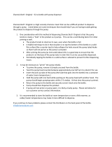
LID SECURING SCREW x2
SYRUP INLETS x4
MAINS POWER INPUT
CO2 IN
VAND IND
BATH FILL
Utility Connection Locations
Commissioning instructions
The following instructions detail the processes to be followed to prime and brix the unit
before putting the unit into dispense mode to dispense drinks. Please read and follow
these instructions carefully.
1. Remove the top cover by removing the securing screws located at the rear of
the unit as shown above.
2. Removethebathllcapandcarefullyandusingafunnel,llthewaterbathwith
coldcleanwateruntilittricklesfromtheoverowtubewhichexitsviaatube
intothedriptray.Thellvolumeisapproximately10litres.
3. Turn on the mains water supply and check for leaks externally and internally.
4. Turn on the CO2 supply and check for leaks externally and internally.
5. Replace the lid and securing screws.
13
Section 3

ALBI ALL-CARB SET UP AND PROGRAMMING INSTRUCTIONS
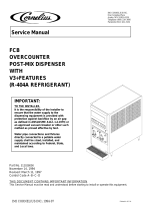
Albi all-carb keypad (note this keypad is also used on the all still unit)
When in programming mode, the keypad is used to adjust and set the various options
for dispense of still and carbonated drinks. The menu appears in the order shown
below:
• Enable\Disable compressor, carbonator pump, and dispense valve.
• Priming of syrup pumps.
• Brix ratio setting of syrups and carbonated water.
• Display of syrup pump total run time in minutes.
• Enable\Disable the dispense of carbonated and still water.
1. Accessing programming mode and button operation
Before commencing programming and brixing, ensure that the mains water, CO2 and
syrup bag in boxes are connected.
Indispensemode,buttons1-4areusedtodispenseavoureddrinksandthebutton(s)
below dispenses still and carbonated water.
In programming mode, the button numbers in the diagrams above correspond to the
numbers shown in the instructions below.
Where H20 is shown as an option, pressing either the still or carbonated water buttons
do the same thing.
STILL/
SODA
1
2
3
4
SODA
STILL
1
2
3
4
1
2
3
4
SODA
STILL
14
Section 3

15
Section 3
2. Putting the unit into programming mode
Plug the unit into the mains power supply
and the initialising screen below will be displayed.
Within four seconds of powering up the unit, press
andholdbuttons1&4andtherstsettingscreen
will be displayed which is detailed in section 4.
3. Enabling\Disabling the fridge system,
carbonator pump and dispense valve
The function of this screen allows the user to
Enable\Disable the fridge system, the carbonator
pump and the dispense valve if required.
Pressing button 3 (+) will move to the next setting
screen and pressing button 2 (-) will move you back
to the previous screen.
Pressing button 4 will take you into the sub
menu to change the settings as below
The top row shows the status of the three options.
X = Disabled Tick = Enabled
Toggle buttons to enable / disable components
Button 2 = fridge
Button 3 = carbonator pump
Button 4 = dispense valve
Pressing button 1 will return you back to the
previous screen. And then press button 3 to take
you to the next setting menu.
Note: when in dispense mode, if the dispense is
disabled, this message will be displayed. If the
fridge and/or the carbonator pump are disabled,
no message is displayed.

16
Section 3
4. Syrup pump priming screen
The function of this screen allows the syrup tubing,
pumps and syrup cooling coils to be primed
through to the dispense valve prior to brixing and
also when changing bag in boxes, if the lines have
been completely emptied.
Pressing button 3 (+) will move to the next setting
screen and pressing button 2(-) will move you back
to the previous setting screen
Pressing button 4 will take you into the sub
menu to prime the syrup lines and pumps.
Pressing buttons 1-4 will manually operate the
syrup pumps to prime the lines through to the
dispense nozzle.
Press either the still or carbonated water button to
exit and return to the previous screen. Then press
button 3 to take you to the next setting menu.
5. Brix ratio settings for carbonated water
and syrups ow rates.
Thefunctionofthisscreenistosettheowrateto
ensure the correct brix ratio.
Pressing button 3 (+) will move to the next setting
screen and pressing button 2(-) will move you back
to the previous setting screen
Thecarbonatedwaterowrateisadjusted
manually at the valve (as described later in this
chapter)
Thewaterowratecheckisdoneusingthe
buttons as described below.
Pressing button 4 will take you into the sub
menutoallowsodaandsyrupowratestobeset
andtoallowa“Testpour”toverifytheowrates
are correct.

17
Section 3
Note:Thecarbonatedwaterowrateshouldbe
setrstandthenthesyrupowrates.
Soda Flow Rate Test Pour:
Ensuring there is a cup under the dispense nozzle,
press the soda button to activate a 7 second soda
test pour.
Measure the volume dispensed, then adjust the
dispensevalveowrate.
See section below: Calculation of carbonated water
ow
The Albi unit nished drink ow rate is typically designed to pour at 1.5oz/sec.
(42.5ml/sec.) @ 5:1 syrup ratio.
Thisisanexampleofhowtheowratesarecalculated:
((Flow rate per second / the total parts of the ratio) x (parts of the ratio for carb/still
water)) x 7 second pour
For1.5ozpersecondnisheddrink,@5:1ratio,thewaterowratecalculationisas
below:
((1.5oz per sec. / 6 total ratio parts) x (5 parts of the ratio)) x 7 seconds = 8.75oz
(246ml)
Once the still water ow rate is set, now set the syrup ow rates:
Calculatethesyrupowvolumeforthe7secondtestpour:
Examplecalculationfor1.5ozpersecondnisheddrink,@5:1ratio:
(1.5oz per sec. / 6 total ratio parts) x 7 seconds = 1.75oz (49.6ml)

18
Section 3
Whilst still in the brix screen, using button 2(-)
& 3(+) select the syrup avour to brix.
Press button. This will take you to the screen to
adjust the syrup pump voltage: Example: 2V4
equates to 2.4 volts.
With a measuring cup / brix cup, under the
dispense nozzle, press button 4. to dispense a
7 sec. syrup pour.
Adjust the pump voltage using buttons 2(-) and 3(+)
toincreaseordecreasethesyruppumpowrate.
Repeat until the correct volume is dispensed.
Press button 1 to move back to the previous
screen. Press button 3(+) to toggle to the next
syrupavour(avour2)
Repeatasaboveuntilallfoursyrupavourshave
been set-up. Press button 1 twice to bring you out
of the Brix screens and back to the main menu.
6. Syrup pump run time total (Information
data only).
Press button 3(+) to move to the next screen.
This screen shows the total run time for each syrup
pump in minutes.
Press button 4 to go to the count screen to
display the total run time for syrup pump 1.
Press buttons 2(-) and 3(+) to toggle between the
run time screens for pumps 2, 3 and 4.
Pressing button 1 will move you back to the total
screen to allow you to move to the next menu
screen.

19
Section 3
7. Disable carbonated water dispense.
Press button +3+ to move to the disable
carbonated water function. This feature allows you
to disable the carbonated water dispense button.
Press button 4 to access the menu.
A tick in the box shows that the carb and still water
dispense is enabled.
Press button 4 to toggle between Enabled and
Disabled.
Press button 1 to go back to the previous menu.
The set-up is now complete.
Press button 1 to get to the dispense mode.
The screen will display READY TO DISPENSE
(providing the dispense is enabled).
8. Option-to switch o the display screen.
Thisturnsothedisplayindispensemode.The
only text that will still be displayed is any error
messages.
Within four seconds of powering up the unit, press
and hold buttons 1 & 3. You will notice the “BL1”
will change to “BL0”.
After a couple of seconds, the screen will go blank.
You can now dispense drinks as normal.
To bring the display back on, power down the unit
and repeat the process. This time you will see the
initialising screen change from “BL0” will change to
“BL1”.

Adjustment of carbonated water ow.
Thisvalvehasasingleowrestrictor,notaow
regulator. These can be adjusted using a 6mm
hexagon Allen key.
Carbonatedwaterowadjusterscrew.
Toincreaseow,turnadjusteranti-clockwise.
The adjuster is accessed by removing the cap in
the membrane switch panel
20
Section 3
Page is loading ...
Page is loading ...
Page is loading ...
Page is loading ...
Page is loading ...
Page is loading ...
Page is loading ...
Page is loading ...
Page is loading ...
Page is loading ...
Page is loading ...
Page is loading ...
Page is loading ...
Page is loading ...
Page is loading ...
Page is loading ...
Page is loading ...
Page is loading ...
Page is loading ...
Page is loading ...
Page is loading ...
Page is loading ...
Page is loading ...
Page is loading ...
Page is loading ...
Page is loading ...
Page is loading ...
Page is loading ...
Page is loading ...
Page is loading ...
Page is loading ...
Page is loading ...
Page is loading ...
Page is loading ...
Page is loading ...
Page is loading ...
Page is loading ...
Page is loading ...
Page is loading ...
Page is loading ...
Page is loading ...
Page is loading ...
Page is loading ...
Page is loading ...
Page is loading ...
Page is loading ...
Page is loading ...
Page is loading ...
/