Page is loading ...

Humidication and Evaporative Cooling
2579082-B EN 1901
INSTALLATION MANUAL
Adiabatic air humidification/air cooling system
Condair ME Direct Feed
READ AND SAVE THESE INSTRUCTIONS

Thank you for choosing Condair
Installation date (MM/DD/YYYY):
Commissioning date (MM/DD/YYYY):
Site:
Model:
Serial number:
Contact
Condair Ltd.
2740 Fenton Road, Ottawa, Ontario K1T3T7
TEL: 1.866.667.8321, FAX: 613.822.7964
EMAIL: na.info@condair.com, WEBSITE: www.condair.com
Proprietary Notice
This document and the information disclosed herein are proprietary data of Condair Ltd. Neither this document, nor
the information contained herein shall be reproduced, used, or disclosed to others without the written authorization
of Condair Ltd., except to the extent required for installation or maintenance of recipient's equipment.
Liability Notice
Condair Ltd. does not accept any liability due to incorrect installation or operation of the equipment or due to the
use of parts/components/equipment that are not authorized by Condair Ltd.
Copyright Notice
© Condair Ltd., All rights reserved.
Technical modications reserved

3Contents
Contents
1 Introduction 4
1.1 General 4
1.2 Notes on the installation manual 4
2 For your safety 6
3 Important notes 8
3.1 Inspection of the delivery 8
3.2 Storing/Transportation/Packaging 8
3.3 Product designation / Which model do you have 9
4 Installation 10
4.1 Installation overviews 10
4.1.1 Typical installation Condair ME Direct Feed (internal installation) 10
4.1.2 Typical installation Condair ME Direct Feed (external installation) 11
4.2 Mounting the evaporative module 12
4.2.1 Notes on positioning the evaporative module 12
4.2.2 Installation procedure evaporative module 15
4.3 Mounting the Hydraulic manifold 28
4.3.1 Mounting the Hydraulic manifold (internal installation) 28
4.3.2 Mounting the Hydraulic manifold (external installation) 29
4.4 Mounting the wall feed through plates 31
4.5 Water installation 34
4.5.1 Notes on water installation 34
4.5.2 Water installation (internal installation) 38
4.5.3 Water installation (external installation) 39
4.6 Mounting the optional control unit 40
4.6.1 Notes on positioning the control unit 40
4.6.2 Recommended access requirements of the control unit 40
4.6.3 Mounting the optional control unit 41
4.7 Electrical installation 42
4.7.1 Notes on electrical installation 42
4.7.2 Electrical installation Condair ME Direct Feed 44
4.7.2.1 Wiring diagram Condair ME Direct Feed with optional stage control unit 44
4.7.2.2 Installation work Condair ME Direct Feed with stage control 45
4.7.2.3 Wiring diagram Condair ME Direct Feed with optional On/Off control unit 49
4.7.2.4 Installation work Condair ME Direct Feed with On/Off control 50
5 Appendix 52
5.1 Inlet water quality requirements 52

4 Introduction
1 Introduction
1.1 General
We thank you for having purchased the Condair ME Direct Feed Evaporative Humidier and Cooler
(Condair ME Direct Feed for short).
To ensure a safe, proper, and economical operation of the Condair ME Direct Feed, please observe
and comply with all information and safety instructions contained in the present documentation as well
as in the separate documentations of the components installed in the humidication system. Improper
use of the Condair ME Direct Feed may result in danger to the user or third parties and/or impairment
of material assets.
If you have questions after reading this documentation, please contact your Condair representative.
They will be glad to assist you.
1.2 Notes on the installation manual
Limitation
The subject of this installation manual is the Condair ME Direct Feed Evaporative Humidier
and Cooler
. The various options and accessories are only described insofar as is necessary for proper
operation of the equipment. Further information on options and accessories can be obtained in the
respective instructions.
This installation manual is restricted to the installation of the Condair ME Direct Feed and is meant for
well trained personnel being sufciently qualied for their respective work.
Please note, some illustrations in this manual may show options and accessories which may not be
supplied as standard or available in your country. Please check availability and specication details with
your Condair representative.
The installation manual is supplemented by various separate items of documentation (such as the opera-
tion manual), which are included in the delivery as well. Where necessary, appropriate cross-references
are made to these publications in the installation manual.

5Introduction
Symbols used in this manual
CAUTION!
The catchword “CAUTION” used in conjunction with the caution symbol in the circle designates notes
in this installation manual that, if neglected, may cause damage and/or malfunction of the unit or
other material assets.
WARNING!
The catchword “WARNING” used in conjunction with the general caution symbol designates safety
and danger notes in this installation manual that, if neglected, may cause injury to persons.
DANGER!
The catchword “DANGER” used in conjunction with the general caution symbol designates safety and
danger notes in this installation manual that, if neglected, may lead to severe injury or even death
of persons.
Safekeeping
Please safeguard this installation manual in a safe place, where it can be immediately accessed. If the
equipment changes hands, the documentation must be passed on to the new operator.
If the documentation gets mislaid, please contact your Condair representative.
Language versions
This installation manual is available in various languages. Please contact your Condair representative
for information.

6 For your safety
2 For your safety
General
Every person working with the Condair ME Direct Feed must have read and understood the installation
manual and the operation manual of the Condair ME Direct Feed before carrying out any work.
Knowing and understanding the contents of the installation manual and the operation manual is a basic
requirement for protecting the personnel against any kind of danger, to prevent faulty operation, and to
operate the unit safely and correctly.
All ideograms, signs and markings applied to the unit must be observed and kept in readable state.
Qualication of personnel
All work described in this installation manual may only be carried out by specialists who are well
trained and adequately qualied and are authorized by the customer.
For safety and warranty reasons any action beyond the scope of this manual must only be carried out
by personnel with appropriate industry recognized qualications or training.
It is assumed that all persons working with the Condair ME Direct Feed are familiar and comply with the
appropriate regulations on work safety and the prevention of accidents.
Intended use
The Condair ME Direct Feed is intended exclusively for air humidication and air cooling in AHU's
or air ducts within the specied operating conditions (see operation manual Condair ME Direct Feed).
Any other type of application, without the written consent of the manufacturer, is considered as not con-
forming with the intended purpose and may lead to the Condair ME Direct Feed becoming dangerous.
Operation of the equipment in the intended manner requires that all the information contained in this
installation manual are observed (in particular the safety instructions).
Danger that may arise from the Condair ME Direct Feed
DANGER!
Risk of electric shock!
The optional Condair ME Direct feed control units contain live mains voltage. Live parts may
be exposed when the control unit is open. Touching live parts may cause severe injury or
danger to life.
Prevention: The control unit must be connected to the mains only after all mounting and installation
work has been completed, all installations have been checked for correct workmanship and the cov-
ers have been relocated properly.
WARNING!
Some type of evaporative material is manufactured from glass bre. Though this material is not classi-
ed as hazardous, it is recommended that Personal Protection Equipment such as gloves, protective
clothing and eye protection are used during handling to protect the user from bres or dust. If dust is
generated during handling it is recommended that respiratory protection is worn.

7For your safety
Correct lifting and handling
Lifting or handling of components always carries an element of risk, and therefore must only be carried
out by trained and qualied personnel. Ensure that any lifting operations have been fully planned and risk
assessed. All equipment should be checked by a skilled and competent health & safety representative.
It is the customer's responsibility to ensure that operators are trained in handling heavy goods and to
enforce the relevant lifting regulations.
Preventing unsafe operation
All persons working with the Condair ME Direct Feed are obliged to report any alterations to the unit that
may affect safety to the owner without delay and to secure such systems against accidental power-up.
Prohibited modications to the unit
No modications must be undertaken on the adiabatic air humidication/air cooling system Condair
ME
Direct Feed without the express written consent of the manufacturer.
For the replacement of defective components use exclusively original accessories and spare parts
available from your Condair representative.

8 Important notes
3 Important notes
3.1 Inspection of the delivery
After receiving:
– Inspect shipping boxes for damage.
Any damages to the shipping boxes must be reported to the shipping company.
– Check packing slip to ensure all parts has been delivered.
All material shortages are to be reported to your Condair representative within 48 hours after receipt
of the goods. Condair assumes no responsibility for any material shortages beyond this period.
– Unpack the parts/components and check for any damage.
It is particularly important that the tank, structural components, and xings (such as studs) are
inspected as damage to these items could affect the structural integrity of the system. If parts/com-
ponents are damaged, notify the shipping company immediately.
– Check whether the components are suitable for installation on your site according to the product
specication (refer to model key in the operation manual).
3.2 Storing/Transportation/Packaging
Storing
Until installation store the system components in its original packaging in a protected area meeting the
following requirements:
– Room temperature: 1 ... 40 °C
– Room humidity: 10 ... 75 %rh
Transportation
For optimum protection of the product, always transport the unit in its original packaging. The packaged
Condair ME unit is able to be transported by trained personnel, using an appropriate lifting/transporting
device from the underside.
WARNING!
The evaporative module must not be transported with the optional droplet separators tted.
WARNING!
It is the customer's responsibility to ensure that operators are trained in handling heavy goods and that
the operators comply with the appropriate regulations on work safety and the prevention of accidents.
Packaging
Keep the original packaging of the components for later use.
In case you wish to dispose of the packaging, observe the local regulations on waste disposal. Please
recycle packaging where possible.

9Important notes
3.3 Product designation / Which model do you have
The product designation and the most important unit data are found on the rating plate xed to the
evaporative module and the control unit.
Information regarding the rating plate and the product key can be found in the operation manual of the
Condair ME Direct Feed.

10 Installation
4 Installation
4.1 Installation overviews
4.1.1 Typical installation Condair ME Direct Feed (internal installation)
1 - Mounting the evaporative module --> see chapter 4.2
2 - Mounting the Hydraulic manifold --> see chapter 4.3
3 - Mounting the wall feed through --> see chapter 4.4
4 - Water installation --> see chapter 4.5
5 - Mounting the control unit --> see chapter 4.6
6 - Electrical installation --> see chapter 4.7
Fig. 1: Typical installation Condair ME Direct Feed (internal installation)
5
4
4
4
4
6
1
2
3
Hydraulic manifold
AHU drain
with trap
Control unit
Electrical
isolator
Water supply line
Wall feed through
Water drain line
with trap
Air ow direction
Evaporative module

11Installation
4.1.2 Typical installation Condair ME Direct Feed (external installation)
1 - Mounting the evaporative module --> see chapter 4.2
2 - Mounting the Hydraulic manifold --> see chapter 4.3
3 - Mounting the wall feed through --> see chapter 4.4
4 - Water installation --> see chapter 4.5
5 - Mounting the control unit --> see chapter 4.6
6 - Electrical installation --> see chapter 4.7
Fig. 2: Typical installation Condair ME Direct Feed (external installation)
4
4
4
6
1
2
3
5
Hydraulic manifold
AHU drain
with trap
Control unit
Electrical
isolator
Water supply line
Water drain line
with trap
Air ow direction
Evaporative module
Wall feed through

12 Installation
4.2 Mounting the evaporative module
4.2.1 Notes on positioning the evaporative module
The design and dimensioning of the AHU/air duct as well as the location of the evaporative module
inside the duct are determined, recorded and set compulsory when planning the entire system. Prior to
installation, however, make sure the following criteria have been taken into consideration:
– The AHU/air duct oor must be designed with a loading capacity capable of supporting the evapora-
tive module’s weight.
– In the area where the evaporative module is installed the oor of the AHU/air duct must offer a plane
support (lengthwise and crosswise).
– The evaporative module must be installed in a waterproof section of the AHU/air duct.
– Downstream, directly after the evaporative module a drain pan with provision for running water
to waste must be installed. The drain must be connected via a drain trap to the waste water line of
the building. The drain trap must be sufciently high and must be lled with water prior to commis-
sioning, so that the drain trap is not emptied by the air pressure in the duct. The drain pan and the
drain trap must be accessible for cleaning and disinfection as part of the periodic maintenance of
the system.
– For installation and maintenance sufciently large access doors before and after the evaporative
module must be available in the AHU/air duct.
– The supply air must be ltered. We recommend to install an air lter with quality standard F7 (EU7)
or better before the evaporative module. If no air lter or an air lter with lower quality is installed an
increased maintenance requirement will result.
– An even air ow over the full cross section of the evaporative module must be guaranteed. If
necessary, rectiers or perforated plates must be installed.
– The evaporative module must be positioned on upstands (supplied) to allow to install the drain pipe
with a downslope through the side wall of the AHU/air duct.
– In case of low ambient temperature the AHU/air duct must be insulated to prevent the moist air from
condensing inside the duct.
– If the AHU is equipped with a heater, make sure it is at least 600 mm (23.6") away from the evapora-
tive module.
– If the evaporative module includes the optional droplet separator cassettes for high air velocities,
then the droplet separator cassettes must be installed.
– Appropriate clearance must be available for the hydraulic manifold (and associated plumbing) when
installing externally.
– For commissioning and maintenance we recommend a minimum of 600 mm (24") of free space
after the evaporative module.
WARNING!
Consideration should be given to the amount of space required after the evaporative module for
access equipment, particularly for taller systems as personnel will require access to the top of the
evaporative module.
– For inspection we recommend 600 mm (24") of free space before the evaporative module. If inspec-
tion access is not required before the module, a minimum clearance of 200 mm (7.9") is acceptable
provided any heater is at least 600 mm (24") away from the evaporative module.

13Installation
Fig. 3: Positioning of the evaporative module (centre drain tank)
Dimension “a”:
ME Direct Feed (internal install): 111 mm / 4.4"
ME Direct Feed (external install): 111 mm / 4.4"
Dimension “b”:
F-Type bre cassettes F75/F85/F95: 395 mm / 15.6"
C-Type bre cassettes C85/C95: 525 mm / 20.7"
Polyester cassettes P85/P95: 525 mm / 20.7"
Recommended service access
min. 600 mm / 24"
Recommended inspection access
600 mm / 24"
(min. 200 mm / 7.9" clearance)
b
Air ow direction
a

14 Installation
Fig. 4: Positioning of the evaporative module (side drain tank)
CAUTION!
The ME evaporative module contains a large reservoir of water when in operation. Install the ME unit
where is no risk of water damage, otherwise make provisions to contain any leakage.
Air ow direction
Recommended inspection access
600 mm / 24"
(min. 200 mm / 7.9" clearance)
a
Recommended service access
min. 600 mm / 24"
b
Dimension “a”:
F-type bre cassettes F75/F85/F95: 395 mm / 15.6"
Polyester cassettes P85/P95: 525 mm / 20.7"
C-type bre cassettes C85/C95: 525 mm / 20.7"
Dimension “b”:
F-type bre cassettes F75/F85/F95: 208 mm / 8.2"
Polyester cassettes P85/P95: 273 mm / 10.7"
C-type bre cassettes C85/C95: 273 mm / 10.7"

15Installation
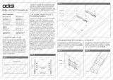
4.2.2 Installation procedure evaporative module
WARNING!
A full risk assessment must be completed by suitably trained personnel prior to installing the ME unit.
There may be increased risk when installing systems that necessitate working at height.
The following risks should be considered (this list is not exhaustive, and there may be additional site
specic risks that will need to be considered):
– Electrical work
– Manual handling
– Musculoskeletal disorders
– Working at height
– Falling objects & objects dropped from higher levels
– Risks arising from the use of Mobile Elevated Work Platforms
– Risk of contact with ceilings, overhead items or asbestos roong while using access equipment
– Adverse weather conditions
– Unsuitable surface and ground
– Other equipment, machinary or supply pipework in the vicinity of the work area
Installation of the ME unit must only be carried out by trained personnel, and all installation equipment
must be checked by a skilled and competent health & safety representative.

16 Installation
1. Mounting the tank upstands to the tank:
• Mounting the tank upstands supplied by Condair: x tank upstands to the tank as shown in
the gure below using the nuts (M8, AF: 13 mm) and washers supplied.
Fig. 5: Mounting the tank upstands to the tank

17Installation
2. Mounting the tank:
• Insert the tank into the AHU/air duct.
WARNING!
Use an appropriate lifting device or handle the tank with the help of another person to posi-
tion it inside the duct. It is the customer's responsibility to ensure that operators are trained in
handling heavy goods and to enforce the relevant lifting regulations.
• Align the tank to the centre of the duct and perpendicular to the duct walls. When aligned fix tank
upstands to the duct floor.
CAUTION!
The installer must take appropriate measures to ensure that the duct oor remains water proof
once the tank upstands has been xed to the duct oor.
• Check that the tank is lengthwise and crosswise exactly horizontal using a level.
Fig. 6: Mounting the tank
=
=

18 Installation
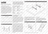
3. Fix frame to the tank:
• Fix the vertical supports to the tank using the nyloc nuts (M6, AF: 10 mm) and M6 washers. Then,
align the vertical supports exactly vertical using a level and tighten the nuts.
• Fix the cross member to the vertical supports using the nyloc nuts (M6, AF: 10 mm) and M6
washers. Then, tighten the nuts.
Fig. 7: Fixing frame to tank

19Installation
4. Fix cross member of frame to AHU/duct ceiling:
• Fix the cross member to the AHU/duct ceiling using appropriate xings (supplied as part of the
installation kit). Before tightening the screws (not supplied) align the vertical supports exactly
vertical using a level.
WARNING!
If the cross member is not secured to the AHU/duct ceiling there is a risk that the evaporative
module could fall over, potentially causing injury or damage.
Fig. 8: Fix cross member to AHU/duct ceiling

20 Installation
5. Mount the blanking plates on the air inlet side (blanking plates available as option):
• Starting on each duct side at the bottom x the side blanking plates to the duct wall using ap-
propriate xings. Before fixing make sure the side blanking plates are aligned exactly vertical
and the free end of the blanking plates touches the side of the corresponding vertical support.
• Starting on one side x the upper blanking plates to the duct ceiling using appropriate xings.
Before fixing make sure the upper blanking plates are aligned exactly perpendicular to the duct
walls and the free ends of the blanking plates touch the cross member of the frame. Also ensure
the ends of the upper blanking plates are touching the side blanking plates.
• Starting on one side x the lower blanking plates to the duct oor using appropriate fixings.
Before fixing make sure the lower blanking plates are aligned exactly perpendicular to the duct
walls and the free ends of the blanking plates touch the tank wall. Also ensure the ends of the
lower blanking plates are touching the side blanking plates.
CAUTION!
The installer must take appropriate measures to ensure that the duct oor remains water proof
once the lower blanking plates have been xed to the duct oor.
Fig. 9: Mounting the optional Condair blanking plates on the air inlet side
/