Page is loading ...

ZUMMESH-JBOX-SIM
Zum™ Sensor Integration
Installation Guide
Description
The Crestron
®
ZUMMESH-JBOX-SIM enables 24 V motion sensors (GLS-ODT-C-NS or
GLS-OIR-C-NS, not included) and an open-loop photo sensor (GLS-LOL, not included) to
be used as part of a Zūm commercial lighting system.
The ZUMMESH-JBOX-SIM powers GLS-ODT-C-NS and GLS-OIR-C-NS motion sensors
wired in parallel as well as a single GLS-LOL photo sensor. The motion sensors can
operate in Occupancy mode (turning the lights on and off) or in Vacancy mode (turning the
lights off only).
NOTE: These models meet the requirements of UL
®
standard 2043 for installation in
an environmental air-handling (plenum) space.
Specications
SPECIFICATION DETAILS
Power Requirements 100-277 Vac, 50/60 Hz
Standby power: <1 W
Sensor Power Output
Output Voltage
Output Current
Output Protection
24 V
250 Ma (sufcient for 4 Crestron motion sensors and
1 Crestron photo sensor)
275 mA Current limit/short-circuit protection
Sensor Inputs
Occupancy Input
Vacancy Input
Photo Input
24 Vdc, max., Threshold to detect motion >8 V
24 Vdc max., Threshold to detect motion >8 V
0-10 V for normal operation, 24 V max.
Environmental
Temperature
Humidity
32º to 104 ºF (0º to 40 ºC)
10% to 90% RH (noncondensing)
Weight 7 oz (180 g)
Additional Resources
Visit the product page on the Crestron website (www.crestron.com)
for additional information and the latest rmware updates. Use a QR
reader application on your mobile device to scan the QR image.
Installation
WARNING: To avoid re, shock, or death, turn off the power at the circuit breaker or
fuse and test that the power is off before wiring!
NOTE: Observe the following points:
• Install and use this product in accordance with appropriate electrical codes and
regulations.
• A licensed electrician should install this product.
To install a ZUMMESH-JBOX-SIM, do the following:
1. Turn the power off at the circuit breaker.
2. Mount the J-box device to the J-box.
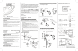
3. Wire the device as shown in the following diagram.
NOTE: The ground connection must be made for proper operation.
ZUMMESH-JBOX-SIM Wiring
Neutral (white)
Hot (black)
Ground (green)
100-277 Vac power
from breaker
Wiring
Photo Sensor Connection Guidelines
The Zūm space can contain only one photo sensor. Wired and wireless photo sensors
cannot be mixed in the same space.
NOTE: Do not use a standard ZUMMESH-OL-PHOTO sensor (not included) if a photo
sensor is already connected to the ZUMMESH-JBOX-SIM photo sensor input.
To wire, use 16-22 AWG wires with a wire-run no greater than 50 feet (15 meters).
Motion Sensor Connection Guidelines
The ZUMMESH-JBOX-SIM can power up to 4 GLS-ODT-C-NS motion sensors which allow
a Zūm space to operate in Occupancy mode (turns lights on and off) or Vacancy mode (only
turns lights off). Occupancy mode or Vacancy mode is determined by the connection that is
made to the ZUMMESH-JBOX-SIM from the GLS-ODT-C-NS.
All sensors attached to the ZUMMESH-JBOX-SIM act as either occupancy or vacancy
sensors. If the connection is made to the O terminal, the motion sensors operate in
Occupancy mode. If the connection is made to the V terminal, the motion sensors operate
in Vacancy mode.
To wire, use 16-22 AWG wires with a wire-run no greater than 250 feet (76 meters)
NOTE: The Zūm space cannot have a mix of occupancy and vacancy sensors.
Connections can be made only to the O terminal or the V terminal.
NOTE: In Occupancy mode, a single motion sensor reporting occupancy will turn the
lights on. All motion sensors must report vacancy before the lights will turn off.
NOTE: In Vacancy mode, all motion sensors must report vacancy before the lights will
turn off.
When power is provided to the Zūm system, the ZUMMESH-JBOX-SIM detects the sensor
connections to the O or V terminal and begins operating in Occupancy or Vacancy mode.
NOTE: If the type of sensor used in the Zūm space is changed (for example, vacancy
sensors replaced occupancy sensors), the entire Zūm space should be power cycled to
reset its operating mode.
Refer to the table for the maximum number of sensors that can be powered by the
ZUMMESH-JBOX-SIM. If additional sensors are needed, they can be connected using an
external power supply. When using an external power supply, tie the grounds together.
MANUFACTURER MODEL MAX. SENSORS
Crestron GLS-ODT-C-NS 4
Crestron GLS-OIR-C-NS 7
Steinel IR Quattro HD COM2-24
IR Quattro HD COM1-24
IR CM COM2-24
7
Steinel US Hallway COM1-24 6
Steinel US Hallway COM2-24 5
Refer to the illustrations that follow for connecting motion sensors and a photo sensor to
the ZUMMESH-JBOX-SIM.
Wiring Four GLS-ODT-C-NS’s and One GLS-LOL to the ZUMMESH-JBOX-SIM
Vacancy Mode
GLS-ODT-C-NS Connections
GLS-ODT-C-NS
GLS-ODT-C-NS
GLS-ODT-C-NS
GLS-LOL
GLS-ODT-C-NS
GLS-LOL Connections
+
-
24 - Power to sensors
Power connection to 24 terminal
Power connection to 24 terminal
Motion sensor connection to V terminal
Photo sensor connection to D terminal
Ground connection to G terminal
Ground connection to G terminal
Power Connection - Red
Photo Sensor Connection - Green
Ground Connection - Black
V - From the motion sensor
D - From the photo sensor
G - Ground connection
Wiring Four GLS-ODT-C-NS’s and One GLS-LOL to the ZUMMESH-JBOX-SIM
Occupancy Mode
GLS-ODT-C-NS Connections
GLS-ODT-C-NS
GLS-ODT-C-NS
GLS-ODT-C-NS
GLS-ODT-C-NS
GLS-LOL Connections
+
-
24 - Power to sensors
Power connection
Power connection
Motion sensor connection to O terminal
Photo sensor connection
Ground connection
Ground connection
O - From the motion sensor
D - From the photo sensor
G - Ground connection
GLS-LOL
CONNECTION CONNECTION
TYPE
WIRE
COLOR
24, 24V, + Power Red
O No Connection N/A
V, OCC Motion sensor Blue
D, Photo sensor Green
G, – Ground Black
CONNECTION CONNECTION
TYPE
WIRE
COLOR
24, 24V, + Power Red
O, OCC Motion sensor Blue
V No connection N/A
D, Photo sensor Green
G, – Ground Black

Setting Up the Daylight Sensor
The ZUMMESH-JBOX-SIM performs daylight harvesting, which uses natural sunlight to
supplement the light in the room. The natural sunlight allows the articial light levels in the
room to be lowered while maintaining the desired light level in the space.
Each dimmer in the room adjusts its light level independently to maintain even lighting
throughout the space. The dimmer does not lower the lights below 10% brightness.
Daylight harvesting is enabled when scene 1 is recalled. Daylight harvesting is disabled
if a scene other than scene 1 is recalled, the light levels are manually adjusted, or the
SENSOR DISABLE button on a keypad is pressed.
NOTE: When Scene 1 is recalled, the lights go to their Scene 1 preset levels before
daylighting adjusts the levels.
NOTE: Only dimmers are affected by daylighting. Switches are not affected.
To congure the Zūm space to properly utilize daylight harvesting, the daylight sensor
must be set up after the space is fully operational.
When setting up the daylight sensor, consider the following:
• Only dimmers react to daylight sensors.
• Calibrate the daylight sensor during the day when the sun is bright. Avoid light
uctuations caused from clouds that are rapidly exposing and hiding the sun.
• Do not stand between the daylight sensor and the windows. Doing so affects the
readings and causes unpredictable lighting in the room.
Calibrate the Daylight Sensor
To calibrate the daylight sensor, do the following:
1. Adjust the dimmer level of all loads in the room to suit the current daylight
conditions. Each dimmer can be set to a different level. Typically, lights closer to
windows are set to a lower light level than lights that are away from windows.
NOTE: To disable daylighting on a dimmer, do not adjust its light level. Dimmers
left on SCENE 1 or brighter during calibration are not affected by Daylighting.
2. Press and hold the SETUP button for 5 seconds to initiate the daylight calibration
process. The LED ashes red to indicate that the calibration process is running. The
calibration process runs for 60 seconds. During the calibration, the lights cycle from
calibration set point level, to Scene 1 level, then off, and then back to Scene 1 level.
NOTE: The red LED ashes red once after 2 seconds. Continue holding until the
LED ashes red a second time, after 5 seconds.
3. After daylight calibration, the room enters Test mode to verify that the proper levels
were set. The Green LED ashes twice, pauses, then repeats to indicate that it’s in
Test mode. Refer to “Test Mode” for details.
Operation
Test Mode
To manually enter Test mode, press and hold the SETUP button for 2 seconds. During Test
Mode, standard delays that allow smooth light transitions are removed which allows rapid
natural light level changes to cause faster articial light changes. The LED ashes Green
twice, pauses, then repeats to indicate that it is in Test mode. The device exits Test mode
after 2 minutes.
To verify daylight sensor calibration, open and close the blinds or block the cover of the
sensor to simulate low outside natural light conditions. The light level should increase.
Opening the blinds or unblocking the cover of the sensor causes light levels to decrease.
Verify Installation
Press the TEST button to ensure that the system is wired properly. All loads in the room
should toggle when the button is pressed. If all loads do not toggle, verify the wiring and
the programming.
Basic Room Setup
A basic single-room Zūm system consists of Zūm mesh devices, i.e., dimmers, switches,
keypads, and sensors. The Zūm mesh devices in the room communicate directly with
each other without the need for a centralized gateway or processor.
To set up a new single-room Zūm system, do the following:
Step 1a: Create a new single-room Zūm system.
Step 2: Add Zūm mesh devices to the room.
Step 3: Finish creating the single-room Zūm system.
To modify an existing Zūm system, do the following:
Step 1b: Place the system in Joining mode.
Step 2: Add Zūm mesh devices to the room.
Step 3: Finish creating the single-room Zūm system.
Step 1a – Creating a Single-Room Zūm System
To create a new single-room Zūm system, rst form a new room.
NOTE: This can be performed on only one device in the room.
NOTE: The device that is used to create the room is automatically added to the room.
The device does not need to be added to the room.
NOTE: A room can be created only from an ac-powered device.
Start a New Single-Room System with a Keypad, Dimmer, or Switch
Press the bottom button 5 times, and then press and hold the bottom button for 2 seconds.
If the device is not factory fresh, press the bottom button 5 times, and then press and
hold the bottom button for 10 seconds. Release the button when the LED lights. The LED
illuminates for 3 seconds and then slowly ashes to indicate that the room is in Joining
mode and that other devices can join the room.
2s or 10s
Start a Single-Room System with a J-Box Device
Press the SETUP button 5 times, and then press and hold the SETUP button for 2 seconds.
If the device is not factory fresh, press the bottom button 5 times, and then press and
hold the SETUP button for 10 seconds. Release the button when the LED lights. The LED
illuminates for 3 seconds and then slowly ashes to indicate that the room is in Joining
mode and that other devices can join the room.
2s or 10s
Step 1b – Expanding an Existing Single-Room Zūm System
To allow other devices to join the room, place the single-room Zūm system into Joining
mode. Joining mode can be enabled from any ac-powered device or battery keypad that is
already part of the room.
Expand a Single-Room Zūm System Using a Keypad
To enter Joining mode, press and hold both the top and bottom buttons for 5 seconds, wait
for the LED to light, and then tap the top button once, and then the bottom button once.
5s
Expand a Single-Room Zūm System Using a J-box Device
To enter Joining mode, tap the SETUP button 2 times, and then tap the TEST button.
Pressing any button on a device that is part of the network takes the system out of joining
mode. Joining mode ends automatically after 4 minutes.
Step 2 - Adding Zūm Mesh Devices to the Room
Adding Zūm mesh devices to a room is quick and easy. Add devices to the room when the
room is in Joining mode. Joining mode is automatically enabled after a single-room Zūm
system is started (see Step 1a). Joining mode can also be enabled manually (see Step 1b).
The LEDs on all ac-powered devices in the system ash when the system is in Joining
mode.
NOTE: A Zūm mesh device can belong to only one room.
NOTE: The Zūm mesh device used to create the room is already part of the network. It
does not need to be added to the network.
To add a J-box dimmer or switch to the room, press the SETUP button 3 times, and then
press and hold the SETUP button for 2 seconds. If the device is not factory fresh, press the
SETUP button 5 times, and then press and hold the SETUP button for 10 seconds. Release
the button when the LED lights. The LED ashes slowly to indicate that it is part of the room
and that the room is still in Joining Mode.
TEST
SETUP
2s or 10s
Step 3 - Finishing the Single-Room Zūm System
Press any button on a device that has already joined the network to end the setup process
(e.g., the top button of a keypad or the SETUP button of a J-box device that is ashing its
LED).
Factory Reset
Perform a factory reset when the device is removed from the network or to remove the
conguration settings. The device must also be factory reset if the device is being moved to
a different system.
NOTE: New-in-box devices do not need to be factory reset before joining a system.
To factory reset the device, press and hold the TEST and SETUP button for 10 seconds.
Release the button when the LED lights. The LEDs and output will turn on.
10s
Install Network Bridge
The Zūm Network Bridge enables Zūm device setup from a mobile app and integrates a
stand-alone Zūm lighting control system with the Zūm hub (not supplied) for a centrally
managed, enterprise-wide lighting control system. The network bridge can be installed to
any J-box device.
1. Using a at-head screwdriver, remove the cover on the J-box device.
2. Ensure that the connector on the network bridge is aligned with the expansion port
on the J-box, and then insert the network bridge into the J-box device. The network
bridge snaps into place.
If necessary, the network bridge can be easily removed. To remove the network bridge, do
the following:
1. Between the J-box and the J-box device, press the side of the network bridge with
your thumb away from the J-box.
2. While pressing on the side of the network bridge, slightly lift the network bridge
up and out of the J-box device. The network bridge should easily remove from the
J-box device.
This product is Listed to applicable UL
®
Standards and requirements tested by Underwriters
Laboratories Inc.
Ce produit est homologué selon les normes et les exigences UL applicables par Underwriters
Laboratories Inc.
Federal Communications Commission (FCC) Compliance Statement
This device complies with part 15 of the FCC Rules. Operation is subject to the following conditions:
(1) This device may not cause harmful interference and (2) this device must accept any interference
received, including interference that may cause undesired operation.
CAUTION: Changes or modications not expressly approved by the manufacturer responsible for
compliance could void the user’s authority to operate the equipment.
NOTE: This equipment has been tested and found to comply with the limits for a Class B digital device,
pursuant to part 15 of the FCC Rules. These limits are designed to provide reasonable protection against
harmful interference in a residential installation. This equipment generates, uses and can radiate radio
frequency energy and, if not installed and used in accordance with the instructions, may cause harmful
interference to radio communications. However, there is no guarantee that interference will not occur in a
particular installation. If this equipment does cause harmful interference to radio or television reception,
which can be determined by turning the equipment off and on, the user is encouraged to try to correct
the interference by one or more of the following measures:
• Reorient or relocate the receiving antenna.
• Increase the separation between the equipment and receiver.
• Connect the equipment into an outlet on a circuit different from that to which the receiver is
connected.
• Consult the dealer or an experienced radio/TV technician for help.
Industry Canada (IC) Compliance Statement
CAN ICES-3 (B)/NMB-3(B)
The product warranty can be found at www.crestron.com/warranty.
The specic patents that cover Crestron products are listed at www.crestron.com/legal/patents.
Certain Crestron products contain open source software. For specic information, please visit
www.crestron.com/opensource.
Crestron, the Crestron logo, and Zūm are either trademarks or registered trademarks of Crestron
Electronics, Inc. in the United States and/or other countries. UL and the UL logo are either trademarks
or registered trademarks of Underwriters Laboratories, Inc. in the United States and/or other countries.
Other trademarks, registered trademarks, and trade names may be used in this document to refer to
either the entities claiming the marks and names or their products. Crestron disclaims any proprietary
interest in the marks and names of others. Crestron is not responsible for errors in typography or
photography.
This document was written by the Technical Publications department at Crestron.
©2017 Crestron Electronics, Inc.
Crestron Electronics, Inc. Installation Guide - DOC. 8238A
15 Volvo Drive, Rockleigh, NJ 07647 (2049725)
Tel: 888.CRESTRON 11.17
Fax: 201.767.7576 Specications subject to
www.crestron.com change without notice.
/