Page is loading ...

UNVENTED (VENT-FREE) GAS
COMPACT CLASSIC HEARTH
®
DUAL BURNER FIREPLACE
OWNER’S OPERATION AND
INSTALLATION MANUAL
For more information, visit www.desatech.com
THERMOSTAT MODELS VDCFTNB AND VDCFTPB
REMOTE-READY MODELS CDCFPRA, CDCFNRA, VDCFRPB AND
VDCFRNB
Shown with Optional Cabinet Mantel/Hearth Base Accessory
WARNING: If the information in this manual is not
vapors and liquids in the vicinity of this or any other
— WHAT TO DO IF YOU SMELL GAS
— Installation and service must be performed by a quali-

www.desatech.com
123502-01C2
WARNING: Improper
alteration, service or
maintenance can cause
-
for correct installation
and operational proce-
additional information
consult a qualified in-
WARNING: This is an
-
from the room in which
for adequate combustion
and ventilation air must
Air
for Combustion and Ven-
tilation
SAFETY
This appliance may be in-
stalled in an aftermarket,*
permanently located,
home, where not prohib-
This appliance is only for
not convertible for use
* Aftermarket: Completion of sale, not for
purpose of resale, from the manufacturer
WARNING: This product
chemicals known to the State
of California to cause cancer or
birth defects or other reproduc-
manual carefully and completely
-
-
sion, electrical shock and carbon
TABLE OF CONTENTS
Safety .................................................................. 2
Product Identication ........................................... 4
Optional Remote Control Accessories ................. 4
Local Codes......................................................... 5
Product Features ................................................. 5
Unpacking............................................................ 5
Hood Assembly .................................................. 6
Air for Combustion and Ventilation ...................... 6
Installation ........................................................... 9
Operation ........................................................... 19
Inspecting Burners............................................. 25
Cleaning and Maintenance ................................ 25
Wiring Diagram .................................................. 26
Troubleshooting ................................................. 27
Specications .................................................... 31
Replacement Parts ............................................ 31
Service Hints ..................................................... 31
Technical Service............................................... 31
Parts .................................................................. 32
Accessories ....................................................... 38

www.desatech.com
123502-01C 3
DANGER: Carbon monoxide
Early signs
of carbon monoxide poisoning resemble the
u, with headaches, dizziness or nausea. If
you have these signs, the replace may not
be working properly.
Have replace serviced. Some people are
more affected by carbon monoxide than oth-
ers. These include pregnant women, people
with heart or lung disease or anemia, those
under the inuence of alcohol and those at
high altitudes.
Natural and
propane/LP gases are odorless. An odor-
making agent is added to the gas. The odor
helps you detect a gas leak. However, the
odor added to the gas can fade. Gas may be
present even though no odor exists.
Make certain you read and understand all
warnings. Keep this manual for reference. It
is your guide to safe and proper operation of
this replace.
WARNING: Do not use a
insert or other accessory not
-
WARNING: Do not allow fans
Avoid any drafts that alter burner
create drafts that alter burner
appliance should be located out
Fireplace front and screen be-
away from hot surfaces to avoid
-
place will remain hot for a time
-
dren when they are in the room
hand-held remote accessory
keep selector switch in the OFF
position to prevent children from
and free from combustible ma-
-
1. This appliance is only for use with the type
of gas indicated on the rating plate. This
appliance is not convertible for use with
other gases.
2. Do not place propane/LP supply tank(s)
inside any structure. Locate propane/LP
supply tank(s) outdoors.
3. If you smell gas
• shut off gas supply
• do not try to light any appliance
• do not touch any electrical switch; do not
use any phone in your building
• immediately call your gas supplier from
a neighbor’s phone. Follow the gas
supplier’s instructions
• if you cannot reach your gas supplier,
call the re department
4. This replace shall not be installed in a
bedroom or bathroom.
SAFETY
Continued

www.desatech.com
123502-01C4
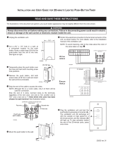
PRODUCT IDENTIFICATION
Ignitor Button
Screen
Fireplace
Cabinet
Log
Control
Knob
Figure 1 - Vent-Free Compact Dual Flame
Fireplace
Hood
Fireplace Cabinet
Logs
Ignitor
Button
Remote Control
(Optional)
Control Knob
Hood
OPTIONAL REMOTE CONTROL ACCESSORIES
SAFETY Continued
5. Do not use this replace as a wood-burn-
ing replace. Use only the logs provided
with the replace.
6.
Do not add extra logs or ornaments such as
pine cones, vermiculite or rock wool. Using
these added items can cause sooting. Do not
add lava rock around base. Rock and debris
could fall into the control area of replace.
7. This replace is designed to be smokeless.
If logs ever appear to smoke, turn off re-
place and call a qualied service person.
Note: During initial operation, slight smok-
ing could occur due to log curing and re-
place burning manufacturing residues.
8. To prevent the creation of soot, follow the
instructions in Cleaning and Maintenance,
page 25.
9.
Before using furniture polish, wax, carpet
cleaner or similar products, turn replace
off. If heated, the vapors from these products
may create a white powder residue within
burner box or on adjacent walls or furniture.
10. This replace needs fresh air ventilation to
run properly. This replace has an Oxygen
Depletion Sensing (ODS) safety shutoff
system. The ODS shuts down the re-
place if not enough fresh air is available.
See Air for Combustion and Ventilation,
page 6. If replace keeps shutting off, see
Troubleshooting, page 27.
11. Do not run replace
• where ammable liquids or vapors are
used or stored.
• under dusty conditions.
12. Do not use this replace to cook food or
burn paper or other objects.
13. Never place any objects in the replace
or on logs.
14. Do not use replace if any part has been
under water. Immediately call a qualied
service technician to inspect the room
replace and to replace any part of the
control system and any gas control which
has been under water.
15.
Turn off and unplug replace and let cool
before servicing. Only a qualied service
person should service and repair replace.
16. Operating replace above elevations of
4,500 feet could cause pilot outage.
17. Do not operate replace if log is broken.
Do not operate replace if log is chipped
(dime-sized or larger).
18. To prevent performance problems, do
not use propane/LP fuel tank of less than
100 lb. capacity.
19. Provide adequate clearances around air
openings.
There are four optional remote controls that
can be purchased separately for Remote-
Ready Models only:
• wall switch
• hand-held ON/OFF remote
• wall thermostat
• hand-held thermostat remote
See Accessories, page 38.

www.desatech.com
123502-01C 5
LOCAL CODES
Install and use replace with care. Follow all
local codes. In the absence of local codes,
use the latest edition of The National Fuel
Gas Code ANSI Z223.1/NFPA 54*.
*Available from:
American National Standards Institute, Inc.
1430 Broadway
New York, NY 10018
National Fire Protection Association, Inc.
Batterymarch Park
Quincy, MA 02269
State of Massachusetts: The installation
must be made by a licensed plumber or
gas tter in the Commonwealth of Mas-
sachusetts.
Sellers of unvented propane or natural
gas-red supplemental room heaters shall
provide to each purchaser a copy of 527
CMR 30 upon sale of the unit.
Vent-free gas products are prohibited for
bedroom and bathroom installation in the
Commonwealth of Massachusetts.
PRODUCT FEATURES
This replace has a pilot with an Oxygen
Depletion Sensing (ODS) safety shutoff
system. The ODS/pilot is a required feature
for vent-free room replaces. The ODS/pilot
shuts off the replace if there is not enough
fresh air.
This replace has a piezo ignitor. This sys-
tem requires no matches, batteries or other
sources to light replace.
THERMOSTATIC HEAT CONTROL
FOR THERMOSTAT-CONTROLLED
MODELS
Thermostat-Controlled models have a ther-
mostat sensing bulb and a control valve.
The thermostat will automatically modulate
the heat output to maintain a consistent
room temperature. This results in greater
replace comfort. This can also result in
lower gas bills.
UNPACKING
1. Remove replace and hood from carton.
Log is wrapped and inside replace. Do
not remove at this time.
2. Remove all protective packaging applied
to replace for shipment.
3. Make sure your replace includes one
hardware packet.
4. Check replace for any shipping damage.
If replace is damaged, call DESA Heat-
ing, LLC at 1-866-672-6040 for replace-
ment parts before returning to dealer.
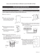
WARNING: Ceramic brick
liners are located behind upper
louver and must be removed
1. Remove screws from top louver and care-
fully remove louver (see Figure 2).
2. Remove ceramic brick liners with protec-
tive packaging. The brick liners will be
installed later.
3. Remove yellow sticker from top of re-
box.
4. Replace top louver using screws removed
in step 1.
Figure 2 - Removing Brick Liners
Top Louver
Screws
Wrapped
Brick Liners

www.desatech.com
123502-01C6
strip and caulk around windows and doors
to keep the cold air out and the warm air in.
During heating months, home owners want
their homes as airtight as possible.
While it is good to make your home energy
efcient, your home needs to breathe. Fresh
air must enter your home. All fuel-burning ap-
pliances need fresh air for proper combustion
and ventilation.
Exhaust fans, replaces, clothes dryers and
fuel burning appliances draw air from the house
to operate. You must provide adequate fresh
air for these appliances. This will insure proper
venting of vented fuel-burning appliances.
The following are excerpts from National Fuel
Gas Code, ANSI Z223.1/NFPA 54, Air for
Combustion and Ventilation.
Figure 4 - Assembling Hood
Hood
Sheet Metal
Screws
Firebox Top
Louver
AIR FOR COMBUSTION AND VENTILATION
WARNING: This heater shall
not be installed in a room or space
unless the required volume of
indoor combustion air is provided
by the method described in the
National Fuel Gas Code, ANSI
Z223.1/NFPA 54, the International
Fuel Gas Code, or applicable
instructions to insure proper fresh
Today’s homes are built more energy efcient
than ever. New materials, increased insulation
and new construction methods help reduce
heat loss in homes. Home owners weather
WARNING: Always have
-
WARNING: Failure to position
the parts in accordance with these
-
Tools Required:
• Phillips screwdriver • slotted screwdriver
• 5/16" hex wrench • scissors
1. If equipped, lift replace screen up and
pull out to remove (see Figure 3). Set
screen aside until installation has been
completed.
2. Cut two plastic straps to remove log from
rebox cavity. Set log aside.
3. An optional blower is available. See Ac-
cessories, page 38. Install optional blower
now. Follow installation instructions pro-
vided with blower.
4. Locate four black Phillips sheet metal
screws in hardware packet.
5. Slide hood between louver and rebox top
and align screw holes.
Figure 3 - Removing and Installing Screen
Screen
Shoulder Screw
HOOD ASSEMBLY
6. Insert screws as shown in Figure 4.
Tighten screws rmly.

www.desatech.com
123502-01C 7
AIR FOR COMBUSTION AND VENTILATION
Continued
All spaces in homes fall into one of the three
following ventilation classications:
1. Unusually Tight Construction
2. Unconned Space
3. Conned Space
The information on pages 6 through 8 will help
you classify your space and provide adequate
ventilation.
The air that leaks around doors and windows
may provide enough fresh air for combustion
and ventilation. However, in buildings of un-
usually tight construction, you must provide
additional fresh air.
construction where:
-
side atmosphere have a continuous
2
and
openable windows and doors and
and door frames, between sole plates
between wall panels, at penetrations
If your home meets all of these three criteria,
Ventilation Air From Outdoors
If your home does not meet all of the three
criteria above, proceed to Determining
Fresh-Air Flow For Fireplace Location
The National Fuel Gas Code, ANSI Z223.1/
NFPA 54 denes a conned space as a space
whose volume is less than 50 cubic feet per
1,000 Btu/hr (4.8 m
3
per kw) of the aggregate
input rating of all appliances installed in that
space and an unconned space as a space
whose volume is not less than 50 cubic feet per
1,000 Btu/hr (4.8 m
3
per kw) of the aggregate
input rating of all appliances installed in that
space. Rooms communicating directly with the
space in which the appliances are installed*,
through openings not furnished with doors, are
considered a part of the unconned space.
* Adjoining rooms are communicating only if
there are doorless passageways or ventilation
grills between them.
DETERMINING FRESH-AIR FLOW
Use this work sheet to determine if you have
a conned or unconned space.
Space: Includes the room in which you will install
replace plus any adjoining rooms with door-
less passageways or ventilation grills between
the rooms.
1. Determine the volume of the space (length
x width x height).
Length x Width x Height =__________cu. ft.
(volume of space)
Example: Space size 16 ft. (length) x 14 ft.
(width) x 8 ft. (ceiling height) = 1792 cu. ft.
(volume of space)
If additional ventilation to adjoining room
is supplied with grills or openings, add the
volume of these rooms to the total volume
of the space.
2. Multiply the space volume by 20 to determine
the maximum Btu/Hr the space can support.
________ (volume of space) x 20 = (Maxi-
mum Btu/Hr the space can support)
Example: 1792 cu. ft. (volume of space) x
20 = 35,840 (maximum Btu/Hr the space
can support)
3. Add the Btu/Hr of all fuel burning appliances
in the space.
Vent-free replace __________ Btu/Hr
Gas water heater* __________ Btu/Hr
Gas furnace __________ Btu/Hr
Vented gas heater __________ Btu/Hr
Gas replace logs __________ Btu/Hr
Other gas appliances* + ________ Btu/Hr
Total = _________ Btu/Hr
* Do not include direct-vent gas appliances.
Direct-vent draws combustion air from the
outdoors and vents to the outdoors.
Example:
Gas water heater ________Btu/Hr
Vent-free replace ________Btu/Hr
Total ________Btu/Hr
4.
Compare the maximum Btu/Hr the space can
support with the actual amount of Btu/Hr used.
________Btu/Hr (maximum space can support)
______ Btu/Hr (actual amount used)
Example: 35,840 Btu/Hr (maximum the
space can support)
40,000 Btu/Hr (actual amount of
Btu/Hr used)
30,000
+ 10,000
= 40,000

www.desatech.com
123502-01C8
AIR FOR COMBUSTION AND VENTILATION
Continued
The space in the previous example is a conned
space because the actual Btu/Hr used is more
than the maximum Btu/Hr the space can sup-
port. You must provide additional fresh air. Your
options are as follows:
A. Rework worksheet, adding the space of an
adjoining room. If the extra space provides
an unconned space, remove door to adjoin-
ing room or add ventilation grills between
rooms. See Ventilation Air From Inside
Building.
B. Vent room directly to the outdoors. See
Ventilation Air From Outdoors.
C. Install a lower Btu/Hr replace, if lower Btu/
Hr size makes room unconned.
If the actual Btu/Hr used is less than the maxi-
mum Btu/Hr the space can support, the space is
an unconned space. You will need no additional
fresh air ventilation.
WARNING: If the area in which
the heater may be operated does
not meet the required volume for
indoor combustion air, combus-
tion and ventilation air shall be
provided by one of the methods
described in the National Fuel
Gas Code, ANSI Z223.1/NFPA 54,
the International Fuel Gas Code,
VENTILATION AIR
This fresh air would come from an adjoining
unconned space. When ventilating to an
adjoining unconned space, you must provide
two permanent openings: one within 12" of the
ceiling and one within 12" of the oor on the
wall connecting the two spaces (see options
1 and 2, Figure 5). You can also remove door
into adjoining room (see option 3, Figure 5).
Follow the National Fuel Gas Code, ANSI
Z223.1/NFPA 54, Air for Combustion and
Ventilation for required size of ventilation
grills or ducts.
Ventilation Air From Outdoors
Provide extra fresh air by using ventilation
grills or ducts. You must provide two perma-
nent openings: one within 12" of the ceiling
and one within 12" of the oor. Connect these
items directly to the outdoors or spaces open
to the outdoors. These spaces include attics
and crawl spaces. Follow the National Fuel
Gas Code, ANSI Z223.1/NFPA 54, Air for
Combustion and Ventilation for required size
of ventilation grills or ducts.
IMPORTANT: Do not provide openings for
inlet or outlet air into attic if attic has a thermo-
stat-controlled power vent. Heated air entering
the attic will activate the power vent.
Figure 6 - Ventilation Air from Outdoors
Outlet
Air
V e ntilated
Attic
Outlet
A
ir
Inlet
Air
Inlet Air
V e ntilated
Crawl Space
T o
Crawl
Space
T o Attic
Figure 5 - Ventilation Air from Inside
Building
Or
Remove
Door into
Adjoining
Room,
Option
3
V e ntilation Grills
Into Adjoining Room,
Option 2
V e ntilation
Grills Into
Adjoining
Room,
Option 1
12"
12"

www.desatech.com
123502-01C 9
INSTALLATION
IMPORTANT: Vent-free replaces add mois-
ture to the air. Although this is benecial,
installing replace in rooms without enough
ventilation air may cause mildew to form from
too much moisture. See Air for Combustion
and Ventilation, page 6.
Note: Your replace is designed to be used in
zero clearance installations. Wall or framing ma-
terial can be placed directly against any exterior
surface on the rear, sides or top of your replace,
except where standoff spacers are integrally at-
tached. If standoff spacers are attached to your
replace, these spacers can be placed directly
against wall or framing materials.
Note: When installing replace directly on
carpeting, tile or other combustible material,
other than wood ooring, the replace shall be
installed on a metal or wood panel extending
the full width and depth of the replace.
Use the dimensions shown for rough openings
to create the easiest installation (see Built-In
Fireplace Installation, page 10).
Use the correct gas type (natural or propane/LP)
for your unit. If your gas supply is not correct,
do not install replace. Call dealer where you
bought replace for proper type replace.
WARNING: This appliance is
Gas type is indicated on the rat-
INSTALLATION ITEMS
Before installing replace, make sure you
have the items listed below.
• external regulator (supplied by installer, for
propane/LP units only)
• piping (check local codes)
• sealant (resistant to propane/LP gas)
• equipment shutoff valve *
• test gauge connection*
• ground joint union
• sediment trap
• tee joint
• pipe wrench
* A CSA design-certied equipment shutoff valve
with 1/8" NPT tap is an acceptable alternative to
test gauge connection. Purchase the optional
CSA design-certied equipment shutoff valve
from your dealer. See Accessories, page 38.
NOTICE: This heater is intended
-
-
WARNING: Never install the
-
WARNING: Never install in a
-
-
-
rents move heat to wall surfaces
-
tobacco smoke, aromatic candles,

www.desatech.com
123502-01C10
Note: If desired, purchase a four-sided pe-
rimeter trim kit for built-in installations. See
Accessories, page 38.
WARNING: Maintain the
minimum clearances shown
If your replace is to be used with an optional
mantel, the installation instructions included
with your mantel shows an CSA approved
method of attaching the replace/mantel sys-
tem to a wall. IMPORTANT: Only use optional
cabinet or corner mantels specied in this
manual. Purchase the optional mantel from
your dealer (see Accessories, page 38).
If your replace is to be recessed into the wall,
see Built-In Fireplace Installation on page 10
to secure your replace into the wall.
CAUTION: If you install the
For convenience and efciency, install re-
place
• where there is easy access for operation,
inspection and service
• in coldest part of room
An optional blower kit is available from your
dealer. See Accessories, page 38. If planning
to use blower, follow instructions provided with
blower for power source.
Minimum Clearances For Side
Combustible Material, Side Wall and
A. Clearances from the side of the replace
cabinet to any combustible material and
wall should follow diagram in Figure 6.
Example: The face of a mantel, bookshelf,
etc. is made of combustible material and
protrudes 3
1
/2" from the wall. This com-
bustible material must be 4" from the side
of the replace opening (see Figure 7).
INSTALLATION
Continued
Figure 7 - Minimum Clearance for
Combustible to Wall
*Minimum 16" from Side Wall
*
Example
B. Clearances from the top of the replace
opening to the ceiling should not be less
than 36".
C. For mantel clearances, see Figure 11 on
page 12.
MINIMUM CLEARANCE TO
COMBUSTIBLE MATERIALS
Top 36", Left and Right Sides 6",
Bottom and Rear 0", Front 36"
Built-in installation of this replace involves
installing replace into a framed-in enclosure.
This makes the front of replace ush with wall.
An optional trim kit accessory is available (see
Accessories, page 38). Trim will extend past
sides of replace approximately 1/2". This will
cover the rough edges of the wall opening. If
installing a built-in mantel above the replace,
you must follow the clearances shown in Figure
11, page 12. Follow the instructions below to
install the replace in this manner.
Actual Framing
Height 26" 26
7
/8"
Front Width 26
3
/4" 26
7
/8"
Depth 14
1
/4" 15
1
/4"
1. Frame in rough opening. Use dimensions
shown in Figure 8, page 11, for the rough
opening. If installing in a corner, use
dimensions shown in Figure 9, page 11,
for the rough opening. The height is 26
7
/
8
"
which is the same as the wall opening
above.

www.desatech.com
123502-01C 11
INSTALLATION
Continued
3. Install gas piping to replace location. This
installation includes an approved exible
gas line (if allowed by local codes) after
the equipment shutoff valve. The exible
gas line must be the last item installed on
the gas piping.
4. If you have not installed hood, follow
instructions on page 6.
5. Carefully set replace in front of rough
opening with back of replace inside wall
opening.
6. Attach exible gas line to replace gas
regulator. See Connecting Equipment
Shutoff Valve to Heater Control, page 14.
7. Bend four nailing anges on outer casing
with pliers (see Figure 10).
8. Attach replace to wall studs using nails
or wood screws through holes in nailing
ange.
9. Check all gas connections for leaks. See
Checking Gas Connections, page 14.
10. If using optional trim kit, install the trim
after nal nishing and/or painting of wall.
See instructions included with trim acces-
sory for attaching trim.
IMPORTANT: When nishing your rebox,
combustible materials such as wall board,
gypsum board, sheet rock, drywall, plywood,
etc. may be butted up next to the sides and
top edge of the rebox. Combustible materi-
als should never overlap the rebox front
facing.
Figure 9 - Rough Opening for Installing
in Corner
Figure 8 - Rough Opening for Installing
in Wall
43
5
/16
"
30
5
/8
"
61
1
/4
"
26
7
/8
"
Figure 10 - Attaching Fireplace to Wall
Studs
Nailing
Flanges
Nails or
Wood
Screws
Wall Studs
2. If installing GA3450TA blower accessory,
do so at this time. Follow instructions
included with blower accessory.
Note: If not installing blower accessory,
you may wish to run electrical wiring to
your replace for future blower installation
(see Accessories, page 38). Use only ap-
proved three-wire electrical wiring.
-
-
cal outlet is included with the
-
cal outlet supplied with the
Note: A qualied installer should make all
electrical connections.
26
7
/
8
"
26
7
/8"
3/4" Off
The Floo
r
Minimum
15
1
/4
"

www.desatech.com
123502-01C12
15"
18"
21"
23"
2
1
/2"
6"
8"
10"
Note:
A
ll vertical
measurements
are from top of
fireplace
opening to
bottom of
mantel shelf. All
measurements
are in inches.
WARNING: Do not allow any
combustible/noncombustible
WARNING: Do not allow
combustible or noncombustible
materials to cover any necessary
WARNING: Never modify or
cover the louvered slots on the
Mantel Clearances for Built-In
Installation
If placing mantel above built-in replace, you
must meet minimum clearance between man-
tel shelf and top of replace opening.
NOTICE: Surface temperatures
-
If installed properly, these tem-
peratures meet the requirement
Follow all minimum clearances
INSTALLATION
Continued
Figure 11 - Minimum Mantel Clearances
for Built-In Installation
Mantel Shelf
Side of Firebox
NOTICE: If your installation does
not meet the minimum clear-
ances shown, you must do one
-
To install mantel or blower accessory, you
must rst remove the upper louver.
1. Lift screen off replace and remove log
set if installed.
2. Remove 4 screws from upper louver (see
Figure 12). Save these screws.
3. Pull upper louver straight out from the
cabinet. Be careful not to scratch the
paint. Set louver aside.
4. Open lower louver door by swinging door
down (see Figure 12).
Figure 12 - Removing Top Louver and
Opening Bottom Louver
Top
Louver
Bottom Louver
Refer to instructions provided with the mantel
for assembly instructions.
Refer to instructions provided with the blower
for assembly instructions.

www.desatech.com
123502-01C 13
Installation must include an equipment shutoff
valve, union and plugged 1/8" NPT tap. Locate
NPT tap within reach for test gauge hook up.
NPT tap must be upstream from heater (see
Figure 14).
IMPORTANT: Install equipment shutoff valve
in an accessible location. The equipment
shutoff valve is for turning on or shutting off
the gas to the appliance.
Check your building codes for any special
requirements for locating equipment shutoff
valve to replaces.
Apply pipe joint sealant lightly to male NPT
threads. This will prevent excess sealant from
going into pipe. Excess sealant in pipe could
result in clogged replace valves.
sealant that is resistant to liquid
INSTALLATION
Continued
WARNING: This appliance
WARNING: A qualified
service person must connect
WARNING: Never connect natu-
-
IMPORTANT: For natural gas, check gas line
pressure before connecting replace to gas
line. Gas line pressure must be no greater
than 14" of water. If gas line pressure is higher,
heater regulator damage could occur.
CAUTION: Never connect pro-
For propane/LP units, the installer must supply
an external regulator. The external regulator will
reduce incoming gas pressure. You must reduce
incoming gas pressure to between 11" and 14"
of water. If you do not reduce incoming gas pres-
sure, replace regulator damage could occur.
Install external regulator with the vent pointing
down as shown in Figure 13. Pointing the vent
down protects it from freezing rain or sleet.
CAUTION: Use only new, black
-
-
* Purchase the optional CSA design-certied
equipment shutoff valve from your dealer. See
Accessories, page 38.
Figure 14 - Gas Connection
CSA Design-Certied
Equipment Shutoff Valve
With 1/8" NPT Tap*
3" Minimum
Approved
Flexible
Gas Line
Pipe Nipple Cap Tee Joint
From External
Regulator (
11"
W.C.**
to 14" W.C.
Pressure)
NATURAL
From Gas Meter
(5" W.C.** to
10.5" W.C.
Pressure)
Sediment Trap
Propane/LP
Supply
Tank
External
Regulator
with Vent
Pointing
Down
Figure 13 - External Regulator With Vent
Pointing Down

www.desatech.com
123502-01C14
INSTALLATION
Continued
We recommend that you install a sediment
trap in supply line as shown in Figure 14, page
13. Locate sediment trap where it is within
reach for cleaning. Install in piping system
between fuel supply and heater. Locate sedi-
ment trap where trapped matter is not likely
to freeze. A sediment trap traps moisture and
contaminants. This keeps them from going
into replace controls. If sediment trap is not
installed or is installed wrong, replace may
not run properly.
SHUTOFF VALVE TO HEATER
CONTROL
Installation Items Needed
• Phillips screwdriver
• sealant (resistant to propane/LP gas, not
provided)
1. Open lower louver (see Figure 15).
is provided to allow accessibility
-
nection to the equipment shutoff
2. Route exible gas line, included, from
fireplace control to equipment shutoff
valve through side access holes in outer
casing.
3. Apply pipe joint sealant lightly to male
threads of gas connector attached to
exible gas line/equipment shutoff valve
(see Figure 16).
-
Figure 15 - Flexible Gas Line Location
(Remote-Ready Unit Shown)
Lower
Louver
Flexible Gas
Line
Figure 16 - Attaching Flexible Gas Line
to Equipment Shutoff Valve
Flexible Gas Line
from Fireplace
Gas Regulator
Provided With
Fireplace
To Gas Regulator (Thermostat-
Controlled Models) or Control
Valve (Remote-Ready Models)
Equipment
Shutoff
Valve
To External Regulator
NATURAL GAS
To Gas Supply
and connections, internal and
external to unit, for leaks after
WARNING: Never use an
Apply a noncorrosive leak detec-
4. Check all gas connections for leaks. See
Checking Gas Connections, below. Feed
exible gas line into replace. Make sure
the entire exible gas line is in replace.

www.desatech.com
123502-01C 15
INSTALLATION
Continued
CAUTION: Make sure exter-
Connecting to Gas Supply,
1. Disconnect appliance with its appliance
main gas valve (control valve) and equip-
ment shutoff valve from gas supply piping
system. Pressures in excess of 1/2 psig
will damage heater regulator.
2. Cap off open end of gas pipe where equip-
ment shutoff valve was connected.
3. Pressurize supply piping system by either
opening propane/LP supply tank valve
for propane/LP gas or opening main gas
valve located on or near gas meter for
natural gas or using compressed air.
4. Check all joints of gas supply piping sys-
tem. Apply noncorrosive leak detection
uid to all joints. Bubbles forming show a
leak.
5. Correct all leaks at once.
6. Reconnect fireplace and equipment
shutoff valve to gas supply. Check recon-
nected ttings for leaks.
1. Close equipment shutoff valve (see Fig-
ure 17).
2. Pressurize supply piping system by either
opening propane/LP supply tank valve
for propane/LP gas or opening main gas
valve located on or near gas meter for
natural gas or using compressed air.
3. Check all joints from gas meter to equip-
ment shutoff valve for natural gas or pro-
pane/LP supply to equipment shutoff valve
for propane/LP (see Figures 18 or 19).
Apply noncorrosive leak detection uid to
all joints. Bubbles forming show a leak.
4. Correct all leaks at once.
CONNECTIONS
1. Open equipment shutoff valve (see Fig-
ure 17).
2. Open main gas valve located on or near
gas meter for natural gas or open pro-
pane/LP supply tank valve.
3. Make sure control knob of replace is in
the OFF position.
4.
Check all joints from equipment shutoff valve
to gas regulator (Thermostat-Controlled
Models) or to gas control valve (Remote-
Ready Models) (see Figures 18 or 19). Apply
noncorrosive leak detection uid to all joints.
Bubbles forming show a leak.
5. Correct all leaks at once.
6. Light replace (see Operation, page 19).
Check all other internal joints for leaks.
7. Turn off replace (see To Turn Off Gas
to Appliance, page 20 for Thermostat-
Controlled Models or page 22 for Remote-
Ready Models).
Figure 18 - Checking Gas Joints
(Propane/LP Only)
Propane/LP
Supply
Tank
Equipment
Shutoff
Valve
Equipment
Shutoff Valve
Gas Meter
Figure 19 - Checking Gas Joints
(Natural Gas Only)
Gas Regulator or
Gas Control Valve
Figure 17 - Equipment Shutoff Valve
Open
Closed
Equipment
Shutoff
Valve
Gas Regulator or
Gas Control Valve

www.desatech.com
123502-01C16
REMOTE CONTROL ACCESSORIES
Remote-Ready Models Only
1. Disconnect jumper wires from the control
valve (see Figure 20).
2. Locate the battery clip mounted on the
back of the receiver (see Figure 21).
3. Slide 9-volt battery (not included) through
the clip.
4. Attach the terminal wires to the battery
(see Figure 21).
5. Connect wires from remote receiver to
control valve as shown in Figure 22.
6. Install remote receiver unit onto remote/
blower bracket using screws provided
(see Figure 22).
Remote Control Unit
1. Remove battery cover on back of remote
control unit.
2. Attach terminal wires to the battery (not
included). Place battery into the battery
housing.
3. Replace battery cover onto remote control
unit.
INSTALLATION
Continued
Figure 20 - Disconnecting Jumper Wires
From Control Valve
Figure 21 - Attaching Battery to Receiver
Battery Clip
9-Volt
Battery
Receiver
Terminal
Wires
Figure 22 - Installing Remote Receiver
Remote
Receiver
White Wire to
TH Terminal on
Control Valve
Red Wire to
TPTH Terminal on
Control Valve
WARNING: Read and fol-
Installation should be done by
WARNING: Do not connect
this thermostat to any electrical
1. Remove jumper wire from control valve
(see Figure 20).
2. Connect one terminal of 25 ft. wire to
the “TH” terminal on the control valve.
Connect the other terminal to the “THTP”
terminal on the control valve. See Figure
24, page 17.
3. Route the 25 ft. wire to a convenient loca-
tion to mount your thermostat (no outside
wall). IMPORTANT: The wire may be
shortened but must not be lengthened.
The thermostat should be mounted 54"
above the oor in a location where there
is good air circulation. Avoid heat sources
such as lamps, direct sunlight, replace
or heat and air conditioning ducts.
9-Volt Battery
Battery
Housing
Figure 23 - Installing Battery in Hand-
Held Remote Control Unit
Battery Cover
Terminal
Wires
Remote Control Unit

www.desatech.com
123502-01C 17
INSTALLATION
Continued
4. Gently remove cover of thermostat from
base. Grasp sides of cover rmly and pull
to separate from base.
5.
Feed electrical wires through rectangular
slots on each side of base (see Figure 25).
WARNING: Do not con-
nect the thermostat to a power
6. Connect one bare wire end to each termi-
nal (“W” and “R”) of the thermostat base
(see Figure 26).
Figure 25 - Back View of Thermostat Base
Feed wires through
rectangular slots
W
R
Figure 26 - Thermostat Base Terminals
“W” and “R”
Terminal “W”
Terminal “R”
Figure 24 - Connecting Wire Terminals
To Wall
Thermostat
or Switch
To Wall
Thermostat
or Switch
Control Valve
WARNING: Read and fol-
Installation should be done by
WARNING: Do not connect
this switch to any electrical
1. Remove jumper wire from control valve
(see Figure 20, page 16).
2. Connect one terminal of 25 ft. wire to the
“TH” terminal on the control valve. Con-
nect other terminal to the “THTP” terminal
on control valve. See Figure 24.
3. Route the 25 ft. wire to a convenient loca-
tion to mount your wall switch (no outside
walls).
WARNING: Do not connect
-
IMPORTANT: The wire may be shortened but
must not be lengthened.
4. Connect one bare wire end to each of the
terminals of the provided wall switch.
5. Install the wall switch and cover in the
wall.
7. Install base onto wall with provided
screws.
8. Move temperature adjustment back and
forth to insure the bimetal is free from
restrictions.
9. Replace cover onto base. (Upon installa-
tion, thermostat must be allowed to sta-
bilize at room temperature for a minimum
of 30 minutes for proper operation).
10. Set temperature adjustment to desired
setting. This thermostat has been elec-
tronically calibrated at the factory. No
adjustment or leveling is necessary.

www.desatech.com
123502-01C18
INSTALLING LOG SET AND
1. Remove log packaging material and
discard packaging. Gently place log over
burner (see Figure 27). Do not allow log to
contact ame. If ame contacts log, soot
will be created.
2. Reattach screen by placing notches in
screen frame over shoulder screws and
pushing down.
INSTALLATION
Continued
Log
Shoulder
Screw
Screen
Figure 27 - Installing Log and Screen
1. Remove packaging from brick liners previ-
ously removed from behind top louver.
Figure 28 - Installing Rear Brick Liner
Figure 29 - Installing Side Brick Liners
Figure 30 - Installing Log
Left Brick
Liner
Brick Liner
Bracket and
Screw
Rear Brick
Liner
Log Set
2. Place rear brick liner against back of re-
box. The left and right brick liners will hold
this liner in place (see Figure 28). Be sure
to hold the rear brick liner while installing
the sides so it will not fall forward.
3. Install left and right brick liners using
brackets and screws from hardware kit
as shown in Figure 29. Screw the bracket
into top of rebox and against brick liners.
Adjust bracket before tightening screw.
4. Remove log packaging material and dis-
card. Gently place log over burner (see
Figure 30). (Do not allow log to contact
ame as this will create sooting.)

www.desatech.com
123502-01C 19
INSTALLATION
Continued
OPERATION
THERMOSTAT-CONTROLLED MODELS
-
Force or attempted repair may result in
the appliance and to replace any part of
LIGHTING
INSTRUCTIONS
WARNING: You must operate
screen is installed before run-
1. STOP! Read the safety information start-
ing in column 1.
FOR YOUR SAFETY
READ BEFORE LIGHTING
WARNING: If you do not fol-
low these instructions exactly,
-
the pilot, follow these instructions
WHAT TO DO IF YOU SMELL GAS
If the knob will not push in or turn by
Figure 31 - Installing Screen
Screen
Screen
Rod
Rings
Screen Assembly
Front Center
Hole for
Right Screen
Assembly
Back Center Hole for
Left Screen Assembly
5. Insert each rod through ten rings located
at top of screen (see Figure 31).
6. Insert rst rod into hole in left side of re-
box. Fasten rod to rear hole near center
of rebox using black Phillips head screw
(see Figure 31).
7. Insert other rod into hole on right side of
rebox and fasten rod to front hole near
center of rebox using remaining sheet
metal screw.

www.desatech.com
123502-01C20
2. Make sure equipment shutoff valve is fully
open.
3. Turn control knob clockwise to the
OFF position.
4. Wait ve (5) minutes to clear out any gas.
Then smell for gas, including near the
oor. If you smell gas, STOP! Follow “B”
in the safety information, page 19. If you
don’t smell gas, go to the next step.
5. Turn control knob counterclockwise
to the PILOT position. Press in control knob
for ve (5) seconds (see Figure 32).
Note: You may be running this replace for
the rst time after hooking up to gas sup-
ply. If so, the control knob may need to be
pressed in for 30 seconds or more. This will
allow air to bleed from the gas system.
• If control knob does not pop out when
released, contact a qualified service
person or gas supplier for repairs.
6.
With control knob pressed in, press and
release ignitor button. This will light pilot. The
pilot is attached to the front burner. If needed,
keep pressing ignitor button until pilot lights.
Note: If pilot does not stay lit, refer to
Troubleshooting, page 27. Also, contact a
qualied service person or gas supplier for
repairs. Until repairs are made, light pilot
with match. To light pilot with match, see
Manual Lighting Procedure, page 21.
7. Keep control knob pressed in for 30 sec-
onds after lighting pilot. After 30 seconds,
release control knob.
Note: If pilot goes out, repeat steps 3
through 7. This replace has a safety inter-
OPERATION Continued
THERMOSTAT-CONTROLLED MODELS
Figure 32 - Control Knob In The OFF
Position
Ignitor
Button
Control
Knob
Figure 33 - Natural Gas Pilot
Thermocouple
Ignitor
Electrode
Pilot Burner
Figure 34 -Propane/LP Gas Pilot
Thermocouple
Ignitor
Electrode
Pilot Burner
TO TURN OFF GAS
1. Turn control knob clockwise to the
OFF position.
2. Turn off all electric power to the appli-
ance (if applicable) if service is to be
performed.
3. Close equipment shutoff valve (see Figure
17, page 15).
THERMOSTAT CONTROL
The thermostat used on this replace senses
the room temperature. At times the room may
exceed the set temperature. If so, the burner
will shut off. The burner will cycle back on
when room temperature drops below the set
temperature.
The control knob can be set to any heat level
between HI and LO.
Note: The thermostat sensing bulb measures
the air near the replace cabinet. This may
not always agree with room temperature (de-
pending on housing construction, installation
location, room size, open air temperatures,
etc.). Frequent use of your replace will let you
determine your own comfort levels.
lock system. Wait one (1) minute for system
to reset before lighting pilot again.
8. Turn control knob counterclockwise
to desired heating level. The burner
should light. Set control knob to any heat
level between HI and LO.
9. To leave pilot lit and shut off burners only,
turn control knob clockwise to the
PILOT position.
CAUTION: Do not try to ad-
/