Page is loading ...

July
1985
FORM:
OM-154S
OWN
ERS
MANUAL
MILLER
ELECTRIC
MFG.
CO.
718
S.
BOUNDS
ST.
P.O.
Box
1079
APPLETON,
WI
54912
USA
Effective
With
Serial
No.
JE830021
MODEL
INTELLIMATIC
SS-12M
INTELLIMATIC
SS-16M
IMPORTANT
Read
and
understand
the
entire
contentS
of
both
this
manual
and
the
power
source
manual
used
with
this
unit,
with
special
emphasis
on
the
safety
material
throughout
both
manuals,
before
installing,
operating,
or
maintaining
this
equipment.
This
unit
and
these
instructions
are
for
use
only
by
persons
trained
and
experienced
in
the
safe
opratlon
of
welding
equipment.
Do
not
allow
untrained
persons
to
install,
operate,
or
maintain
this
unit.
Contact
your
distributor
if
you
do
not
fully
understand
these
instructions.
PRINTED
IN
U.S.A.

LIMITED
WARRANTY
EFFECTIVE:
FEBRUARY
25,
1985
This
warranty
supersedes
all
previous
MILLER
warranties
and
is
ex
clusive
with
no
other
guarantees
or
warranties
expressed
or
implied.
LIMITED
WARRANTY
-
Subject
to
the
terms
and
condi-
In
the
case
of
Millers
breach
of
warfenty
or
any
other
duty
~k
~
tions
hereof,
Miller
Electric
Mtg.
Co.,
Appleton,
Wisconsin
with
respect
to
die
quailty
of
any
goods,
the
exckÆve
~u.ed~
warrants
to
its
Distributor/Dealer
that
all
new
and
unused
therefore
shall
be,
at
Millers
option
11)
repair
or
(2)
replacement
~*\
Equipment
fumlahed
by
Miller
is
free
from
defect
in
workman-
or,
where
author~ed
ui
writing
by
Miler
in
appropnata
~,
(3)
(~!
)
ship
and
material
as
of
the
time
and
place
of
delivery
by
Miller.
the
reasonable
cost
of
repair
or
re
lecament
at
an
author~ed
No
warranty
is
made
by
Miller
with
respect
to
engines,
trade
Miller
service
station
or
(4)
payment
of
or
credit
for
the
purchase
~
accessories
or
other
items
manufactured
by
others.
Such
price
(less
reasonable
depreciation
based
upon
actual
use)
upon
~
engines,
trade
accessories
and
other
items
are
sold
subject
to
return
of
the
goods
at
Customers
rik
and
~
MILLERs
)
the
wansntiss
of
their
respective
manufacturers,
if
any
.
All
option
of
repair
or
replaoeniam
will
be
F.O.B.,
Fectori,
at
S~
engines
are
warranted
by
their
manufacturer
for
one
yw
from
Appleton
WlacoriIn,
or
F.O.B.,
at
a
MILLER
author~ed
service
~
data
of
original
purchase,
except
Tecumsuh
engines
which
fadhty,
therefore
no
cc..
.
for
usi
Istion
costs
of
~
hive
a
two
year
warranty,
any
kind
wB
be
all~ved.
Upon
receipt
of
notice
of
apparent
defect
or
faikjre,
Miller
shall
Uweuct
the
cluimant
on
the
warranty
4
Except
sp.ciflsd
below,
Millers
warranty
does
not
apply
claim
procedurse
to
be
followed.
r~
to
components
having
normal
uuiful
life
of
lees
than
one
(1)
yesr,
such
as
spot
welder
ups,
riley
and
contactor
ponts,
MILLERMATIC
parts
that
come
in
contact
with
the
welding
ANY
EXPRESS
WARRANTY
NOT
PROViDED
HEREIN
AND
~
wire
including
noulss
end
nozzle
insulators
where
failure
does
ANY
IMPUED
WARRANTY,
GUARANTY
OR
REPRESENTA
~
not
result
from
defect
in
workmanship
or
material.
TION
AS
TO
PERFORMANCE,
AND
ANY
REMEDY
FOR
BREACH
OF
CONTRACT
WHICH,
BUT
FOR
ThIS
PROVISION.
Miller
shill
be
required
to
honor
warranty
claims
on
war-
MIGHT
ARISE
BY
IMPUCATION,
OPERATION
OF
LAW,
~
ranted
Equipment
in
the
.vsnt
of
failure
resulting
from
e
defect
CUSTOM
OF
TRADE
OR
COURSE
OF
DEALiNG.
INCLUDING
~
within
the
following
periods
from
the
dii.
of
delivery
of
Equip-
ANY
IMPUED
WARRANTY
OF
MERCHANTABILiTY
OR
OF
,~
mint
to
die
original
user:
FITNESS
FOR
PARTiCULAR
PURPOSE,
WITH
RESPECT
TO
ANY
AND
ALL
EQUIPMENT
FURNISHED
BY
MILLER
IS
EX
1.
Arc
welders,
power
sources
and
components
....
1
year
CLUDED
AND
DISCLAIMED
BY
MILLER.
~\
2.
Original
main
p~r
rectifiers
3
years
(labor-lysur
only)
3.
Alw.Jdiig
~sis.
feeder/guns
and
p~ris
v~,th.,...
90
de~
EXCEPT
AS
EXPRESSLY
PROVIDED
BY
MILLER
IN
4.
AllotherMiliermutic
Feeders
1
year
WRmP4G,
MILLER
PRODUCTS
ARE
INTENDED
FOR
5.
Rapl.csmsntorrepeirparis,exclusiveoflibor..
B0days
ULTIMATE
PURCHASE
BY
COMMERCIAL/INDUSTRIAL
6.
Batteries
6
months
USERS
AND
FOR
OPERATION
BY
PERSONS
TRAINED
AND
EXPERIENCED
IN
ThE
USE
AND
MAINTENANCE
OF
tr~
ie
notified
in
writing
within
thIrty
(30)
days
WELDING
EQUIPMENT
AND
NOT
FOR
CONSUMERS
OR
of
the
due
of
such
failure.
CONSUMER
USE.
MILLERS
WARRANTiES
DO
NOT
EICTEND
~T~TOJ

ERRATA
SHEET
After
this
manual
was
printed,
refinements
in
equipment
design
occurTed.
This
sheet
iists
exceptions
to
data
appearing
later
In
this
manuai.
AMENDMENT
TO
SECTiON
3-
INSTALLATION
Amend
Section
3-1.
LOCATION
AND
ASSEMBLY
Delete
Steps
h,
i,
j,
and
k
of
Subsection
B.
Assembly,
Step
2.
Post
Supporf~
Amend
Subsection
B.
Assembly,
Steps
Ic.,
3c.,
and
4c.
to
read
as
follows:
Complete
Steps
c
thru
g
in
Subsection
2.
Post
Support
Replace
Sections
3-5
and
3-22
with
the
following:
INSTALLATION
OF
OPTIONAL
WIRE REEL
AND
REEL-TYPE
WIRE
(Figure
3-3)
1.
Remove
retaining
nng
and
if
applicable
wire
reel
assembly
from
hub.
2.
Lay
wire
reel
assembly
flat
on
a
table
or
floor.
3.
Remove
spanner
nut
from
wire
reel
assembly.
4.
Remove
wire
retainer,
and
install
wire
onto
wire
reel.
Be
sure
that
wire
feeds
off
top
of
reel.
5.
Reinstall
wire
retainer
and
spanner
nut
onto
wire
reel.
6.
Slide
wire
reel
assembly
onto
hub,
and
rotate
assembly
until
hub
guide
pin
is
seated
In
reel.
7.
Reinstall
retaining
ring
onto
hub.
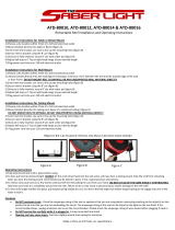
Amend
Figure
3-3.
Reel
Installation
R.t.ining
Ring
Sp.nn.r
Nut
Hub
T8.CeC
038.A
Wirs
Ritsinir
Hub
FIgure
3-3.
Reel
Installation

Add
Section
3-1
1A.
SAFETY
COLLAR
REMOVAL
WARNING:
RELEASE
OF
SPRING
PRESSURE
WIThOUT
BOOM
ATTACHED
can
cause
serious
personal
Injury
and
equipment
damage.
Perform
installation
exactly
as
outlined
in
the
following
step-by-step
instructions.
Do
not
remove
safety
collar
until
instructed
to
do
so.
Retain
safety
collar
for
future
disassembly
use.
A
safety
collar
is
provided
on
top
of
the
post
to
maintain
spring
pressure
and
prevent
vertical
movement
during
installation.
The
collar
is
required
whenever
to
boom
is
disassembled
or
relocated.
To
remove
the
safety
collar,
proceed
as
follows:
1.
Grasp
bar
and
pull
boom
down
slightly.
The
boom
should
be
pulled
down
only
far
enough
to
remove
the
pressure
which
is
applied
to
the
safety
collar.
2.
Remove
the
safety
collar,
and
retain
for
future
use.
3.
The
boom
should
now
balance
in
any
position
from
horizontal
to
60
degrees
above
horizontal.
It
the
boom
does
not
balance
properly,
proceed
to
Section
3-12.
Amend
Figure
3-9.
DIP
Switches
For
Four
Schedules
LCD
I
___
___
I
7
I_c~s
I
~
I_CDP
RPS.4
Switch
CDI
Trigger
Dual
Scboduls
L
CD]
Trigger
Latch
F~J
7
Timid
Abort
Is
Error
Shutdown
E
CDIS
Amps
Display
Q]4
Motors
F
Cyclis
I
CDII
Arc
Hours
Rsot
I
~
I
a
Motor
Rash
Error
Diubi.
Volts
Corvscdon
Intolhimits
Dual
~J}LowS_
Standerd
Rsssrvd
For
Future
Options
Rash
Error
Enshl
No
Volts
Correction
lntslliwold
Singlo
08$-SM
Switch
No
Trigger
Dual
Sch.dulo
No
Tdgsr
Latch
No
limed
Abort
Error
Slink
Only
No
Amp
Display
No
At
Hours
Rust
~~~-J
}
High
Specd
TB-0Q7
552
FIgure
39.
DIP
Switch
Positions
Amend
Section
3-181.
INTERNAL
PROGRAM
OPTIONS:
SELECTOR
SWITCH
I.
PROGRAM
SELECTOR
Place
the
DIP
switch
in
the
RPS-4
position
if
the
RPS-4
option
is
to
be
used.
Place
the
DIP
switch
in
the
DSS-9M
position
if
the
RPS-4
option
is
not
to~used.
IMPORTANT:
Error
A-b
will
be
displayed
during
Program
C
if
RP$-4
is
plugged
in
arid
the
DIP
switch
is
not
in
the
RPS-4
position.
If
the
RPS-4
option
is
not
plugged
in
and
the
DIP
switch
is
in
the
RPS-4
position,
only
Program
A
will
be
displayed.
Add
the
following
Subsections
to
3-18.
INTERNAL
PROGRAM
OPTIONS
J.
SINGLE/DUAL
Place
the
DIP
switch
in
the
Single
position
for
single
gun,
factory
set
position.
OM-1549
Page
2

K.
INTELLIMATE
Place
the
DIP
switch
in
the
Intellimate
position
when
using
this
wire
teederwith
an
INTELLIMATE
DW
interface
control
and
a
DELTAWELD
welding
power
source.
Place
the
DIP
switch
In
the
Intelliweld
position
when
using
this
wire
feeder
with
and
INTELLI
WELD
welding
power
source.
L.
VOLTS
CORRECTION
Place
the
DIP
switch
in
the
Volts
Correction
position
when
using
this
wire
feeder
with
an
INTELLIMATE
OW
interface
control.
Placing
the
DIP
switch
in
the
Volts
Correction
position
provides
the
unit
with
the
Digital
Voltage
Control
function
when
using
this
wire
feederwith
a
DELTAWELD
welding
power
source.
Place
the
DIP
switch
in
the
Intelliweld
position
when
using
this
wire
feeder
with
an
INTELLIWELD
welding
power
source.
M.
FLASHING
ERROR
DISABLE
Place
the
DIP
switch
in
the
Flashing
Error
Disable
position
to
disable
the
Error
Blink/Error
Shutdown
function
of
the
wire
feeder.
Place
the
DIP
switch
in
the
Flashing
Error
Enable
position
to
allow
normal
operation
of
the
Error
Blink/Error
Shutdown.
Dia.
Part
Replaced
**
Mkgs.
No.
With
Description
Quantity
2-13
604
109
604
109
WIRE
(qty
chg)
1
ft
3-47
045
766
110 733
OPTICAL
ENCODER
DISC
1
6-5
PC4
089
900
107
721
CIRCUIT
CARD,
power
supply
(EU
w/JG023762)
I
6-19
PC3
097
180
121
436
CIRCUIT
CARD,
interface
(Elf
w/JJ365634
thru
JJ405391)
1
6-19
PC3
121
436
121
472
CIRCUIT
CARD,
interface
(EU
w/JJ405392
&
following)
1
6-28
092
492
108
196
CIRCUIT
CARD,
filter
(Elf
w/JG029780)
1
9-10
056
416
108
008
REEL,
wire
(consisting
of)
1
108
861
NUT,
spanner-spool
support
1
108
858
RETAINER,
spool
support
1
108
857
SUPPORT,
reel
support
4
~First
digit
represents
page
no
-
digits
following
dash
represent
Item
no.
BE
SURE
TO
PROVIDE
MODEL
AND
SERIAL
NUMBER
WHEN
ORDERING
REPLACEMENT
PARTS.
OM-1549
Page
3

2
C
j
AMENDMENT
TO
SECTION
11
-
MAINTENANCE
&
TROUBLESHOOTING
Amend
Figure
12-1.
CIrcuit
Diagram
For
Weld
Control
I
OM-1549P1Qe4

j4IIV.
f
&
-4--.
p
Circuit
Diagram
No.
C-W9
687
FIgure
12-1.
CircuIt
Diagram
For
Weld
Control
Effective
With
Serial
No.
JG029780

Amend
Figure
12-3.
CIrcuit
Diagram
For
Power
Supply
Board
c014.
7
+24
3
0301
0302
IFC.
coN.
I
OISP.
coN.
2
DIGITAL
CoN.
~----->
12
~
_____
I/O
RC63
1.15
10
TO
I/O
P~59
~
MAMJAL/FEEDER
SW.
>
4)
~>
9
TO
I/O
R~59
>
7_~
)IIIOTOR
TACH.
~J.tLL.>6J
________.LL>
8
TO
I/O
R~59
.->
3
TRIGGER
>2
~
I
R~67
Circuit
Diagram
No.
A-i
07
741
Flgura
12-3.
CIrcuit
Diagram
For
Powsr
Supply
Board
PC4
Effictivi
With
Slilal
Plo.
JG023762
Add
Figure
12-4.
CircuIt
Diagram
For
T~h.
Board
PC5
+10
6
01W
..I0
4.5
VP
il00~j-
if
C303
~C304
/
LED2~
.1
.1
I
03041
03031
_J~___
I_
rr
-24
2k
RC66
TO
INTaLIWEO
r~w~
I
C,
308
VP
Figuri
12-4.
CIrcuit
Diagram
For
Tach.
Board
PCS
Circuit
Diagram
No.
A094
456
OM-1549
P.~i
6

TABLE
OF
CONTENTS
Section
No.
Page
No.
SECTION
1
-
SAFETY
RULES
FOR
OPERATION
OF
ARC
WELDING
POWER
SOURCE
1
-
1.
Introduction
1
1
-
2.
General
Precautions
1
1
-
3.
Arc
Welding
4
1
-
4.
Standards
Booklet
Index
6
SECTION
2
-
INTRODUCTION
2
-
1.
General
Information
And
Safety
7
2
-
2.
Receiving-Handling
7
2
-
3.
Description
7
SECTION
3
-
INSTALLATION
3
-
1.
Location
And
Assembly
8
3
-
2.
Drive
Motor
9
3
-
3.
Installation
Of
Wire
Support
9
3
-
4.
Reinstallation
Of
Hub
Assembly
9
3
-
5.
Installation
Of
Wire
Reel
10
3
-
6.
Drive
Roll
And
Wire
Guide
Installation
10
3
-
7.
Water
Control
Kit
tOptionat)
Connections
11
3
-
8.
Shielding
Gas
Connections
12
3
-
9.
Weld
Cable
Connection
12
3-10.
Optional
Process
Selector
Control
Installation
12
3-11.
Welding
Gun
Connections
14
3-12.
Boom
Adjustments
14
3-13.
Pulley
Adjustment
14
3-14.
Motor
Control
Connection
15
3-15.
Gun
Trigger
Connection
15
3-16.
Weld
Cable
Connection
15
3-17.
Voltage
Sensing
Connections
15
3-18.
Internal
Program
Options
15
3-19.
Presetting
Internal
Program
Options
17
3-20.
Weld
Control
-
Welding
Power
Source
Interface
Connection...
17
3-21.
Installation
Of
Spool-Type
Wire
17
3-22.
Installation
Of
Reel-Type
Wire
17
3-23.
Adjustment
Of
Hub
Tension
17
3-24.
Welding
Wire
Threading
17
SECTION
4
-
TERMINOLOGY
SECTiON
5-
PRESETTiNG
SEMIAUTOMATiC
WELDING
PROGRAMS
SECTION
6
-
SEMIAUTOMATIC
WELDING:
KEY
SWITCH
IN
RUN
POSITION
6
-
1.
Normal
Welding
Without
Dual
Scheduling
21
6
-
2.
Dual
Scheduling
Via
The
Gun
Trigger
21
6
-
3.
Dual
Scheduling
Via
The
DSS-9M
22
6
-
4.
Timed
Welds
23

Section
No.
Page
No.
SECTION
7
-
SEMIAUTOMATIC
WELDING:
KEY
SWITCH
IN
SET
POSITION
7
-
1.
Normal
Welding
Without
Dual
Scheduling
25
7
-
2.
Dual
Scheduling
Via
The
Gun
Trigger
25
7
-
3.
Dual
Scheduling
Via
The
DSS-9M
25
7
-
4.
Dual
Scheduling
Via
The
Program
Select
Pushbutton
26
7
-
5.
Timed
Welds
~26
SECTION
8
-
PRESETTING
MANUAL
WELDING
&
CUTTING
PARAMETERS
8
-
1.
CP
Mode
Operation
27
8
-
2.
CC
Mode
Operation
28
SECTION
9
-
MANUAL
WELDING.
CUTTING
&
GOUGING:
KEY
SWITCH
IN
RUN
POSITION
9
-
1.
CP
Mode
Operation
28
9
-
2.
CC
Mode
Operation
28
SECTION
10
-
MANUAL
WELDING,
CUTTING
&
GOUGING:
KEY
SWITCH
IN
SET
POSITION
10-
1.
CPModeOperetion
29
10-2.
CCModeOperation
29
SECTION
11
-
MAINTENANCE
&
TROUBLESHOOTING
11
-
1.
Inspection
And
Upkeep
29
11
-
2.
Cleaning
Of
Drive
Rolls
30
11
-
3.
Motor
Overload
Breaker
30
11
-
4.
Brush
Inspection
&
Replacement
30
11
-
5.
Diagnostic
Displays
31
11
-
6.
Microprocessor
Battery
31
11
-
7.
Clearing
The
Weld
Program
Memory
(RAM)
31

SECTION
1
-
SAFETY
RULES
FOR
OPERATION
OF
ARC
WELDING
POWER
SOURCE
1-1.
INTRODUCTION
-
We
learn
by
experience.
Learning
safety
through
personal
experience,
like
a
child
touching
a
hot
stove
is
harmful,
wasteful,
and
un
wise.
Let
the
experience
of
others
teach
you.
Safe
practices
developed
from
experience
in
the
use
of
welding
and
cutting
are
described
in
this
manual.
Research,
development,
and
field
experience
have
evolved
reliable
equipment
and
safe
installation,
opera
tion,
and
servicing
practices.
Accidents
occur
when
equipment
is
improperly
used
or
maintained.
The
reason
for
the
safe
practices
may
not
always
be
given.
Some
are
based
on
common
sense,
others
may
require
technical
volumes
to
explain.
It
is
wiser
to
follow
the
rules.
Read
and
understand
these
safe
practices
before
at
tempting
to
install,
operate,
or
service
the
equipment.
Comply
with
these
procedures
as
applicable
to
the
par
ticular
equipment
used
and
their
instruction
manuals,
for
personal
safety
and
for
the
safety
of
others.
Failure
to
observe
these
safe
practices
may
cause
serious
injury
or
death.
When
safety
becomes
a
habit,
the
equipment
can
be
used
with
confidence.
These
safe
practices
are
divided
into
two
Sections:
1
-
General
Precautions,
common
to
arc
welding
and
cutting;
and
2
-
Arc
Welding
(and
Cutting)
(only).
Reference
standards:
Published
Standards
on
safety
are
also
available
for
additional
and
more
complete
pro
cedures
than
those
given
in
this
manual.
They
are
listed
in
the
Standards
Index
in
this
manual.
ANSI
Z49.1
is
the
most
complete.
The
National
Electrical
Code,
Occupational
Safety
and
Health
Administration,
local
industrial
codes;
and
local
inspection
requirements
also
provide
a
basis
for
equip
ment
installation,
use,
and
service.
1-2.
GENERAL
PRECAUTIONS
Dlffrsnt
a,c
waldIn~
pioc.uus,
sisciruda
alloy.,
and
fluxes
can
produce
dlffsrout
turns.,
gaas.
and
radladon
lsvsls
In
addidon
to
the
information
In
thi,
manual,
bs
suru
to
consult
~ax
and
.l.~
trods
manufactorsre
for
.
ts~hnkal
dat.
and
pr.caudonary
msssw.s
conow~g
thalr
matsdal.
A.
Burn
PreventIon
Wear
protective
clothing
-
gauntlet
gloves
designed
for
use
in
welding,
hat,
and
high
safety-toe
shoes.
Button
shirt
collar
and
pocket
flaps,
and
wear
cufflesa
trousers
to
avoid
entry
of
sparks
and
slag.
Wear
helmet
with
safety
goggles
or
glasses
with
side
shields
underneath,
appropriate
filter
lenses
or
plates
(protected
by
clear
cover
glass).
This
is
a
MUST
for
welding
or
cutting,
(and
chipping)
to
protect
the
eyes
from
radiant
energy
and
flying
metal.
Replace
cover
glass
when
broken,
pitted,
or
spattered.
See
1
-3A.2.
Avoid
oily
or
greasy
clothing.
A
spark
may
ignite
them.
Hot
metal
such
as
electrode
stubs
and
workpieces
should
never
be
handled
withotft
gloves.
Medical
first
aid
and
eye
treatn~ent
First
aid
facilities
and
a
qualified
first
aid
person
should
be
available
for
each
shift
unless
medical
facilities
are
close
by
for
im
mediate
treatment
of
flash
burns
of
the
eyes
and
skin
burns.
Ear
plugs
should
be
worn
when
working
on
overhead
or
in
a
confined
space.
A
hard
hat
should
be
worn
when
others
work
overhead.
Flammable
hair
preparations
should
not
be
used
by
per
Sons
intending
to
weld
or
cut.
B.
Toxic
Fume
Prevention
Severe
discomfort,
illness
or
death
can
result
from
fumes,
vapors,
heat,
or
oxygen
enrichment
or
depletion
that
welding
(or
cutting)
may
produce.
Prevent
them
with
adequate
ventilation
as
described
in
ANSI
Stan
dard
Z49.1
listed
1
in
Standards
index.
NEVER
ventilate
with
oxygen.
Lead
-,
cadmium
-,
zinc
-,
mercury
-,
and
beryllium
-
bearing
and
similar
materials,
when
welded
(or
cut)
may
produce
harmful
concentrations
of
toxic
fumes.
Ade
quate
local
exhaust
ventilation
must
be
used,
or
each
person
in
the
area
as
well
as
the
operator
must
wear
an
air-supplied
respirator.
For
beryllium,
both
must
be
us
ed.
Metals
coated
with
or
containing
materials
that
emit
toxic
fumes
should
not
be
heated
unless
coating
is
removed
from
the
work
surface,
the
area
is
well
ven
tilated,
or
the
operator
wears
an
air-supplied
respirator.
Work
in
a
confined
space
only
while
it
is
being
ven
tilated
and,
if
necessary,
while
wearing
an
air-supplied
respirator.
Gas
leaks
in
a
confined
space
should
be
avoided.
Leaked
gas
in
large
quantities
can
change
oxygen
con
centration
dangerously.
Do
not
bring
gas
cylinders
into
a
confined
space.
Leaving
confined
space,
shut
OFF
gas
supply
at
source
to
prevent
possible
accumulation
of
gases
in
the
space
if
downstream
valves
have
been
accidently
opened
or
left
open.
Check
to
be
sure
that
the
space
is
safe
before
re-entering
it.
Vapors
from
chlorinated
solvents
can
be
decomposed
by
the
heat
of
the
arc
(or
flame)
to
form
PHOSGENE,
a
OM-1549
Page
1

highly
toxic
gas,
and
other
lung
and
eye
irritating
pro
ducts.
The
ultraviolet
(radiant)
energy
of
the
arc
can
also
decompose
trichloroethylene
and
per
chioroethylene
vapors
to
form
phosgene.
DO
NOT
WELD
or
cut
where
solvent
vapors
can
be
drawn
into
the
welding
or
cutting
atmosphere
or
where
the
radiant
energy
can
penetrate
to
atmospheres
containing
even
minute
amounts
of
trichloroethylene
or
per
chloroethylene.
C.
Fire
and
Explosion
Prevention
Causes
of
fire
and
explosion
are:
combustibles
reached
by
the
arc,
flame,
flying
sparks,
hot
slag
or
heated
material;
misuse
of
compressed
gases
and
cylinders;
and
short
circuits.
BE
AWARE
THAT
flying
sparks
or
falling
slag
can
pass
through
cracks,
along
pipes,
through
windows
or
doors,
and
through
wall
or
floor
openings,
out
of
sight
of
the
goggled
operator.
Sparks
and
slag
can
fly
35
feet.
To
prevent
fires
and
explosion:
Keep
equipment
clean
and
operable,
free
of
oil,
grease,
and
(in
electrical
parts)
of
metallic
particles
that
can
cause
short
circuits.
If
combustibles
are
in
area,
do
NOT
weld
or
cut.
Move
the
work
if
practicable,
to
an
area
free
of
combustibles.
Avoid
paint
spray
rooms,
dip
tanks,
storage
areas,
yen
tilators.
If
the
work
cannot
be
moved,
move
com
bustibles
at
least
35
feet
away
out
of
reach
of
sparks
and
heat;
or
protect
against
ignition
with
suitable
and
snug-fitting,
fire-resistant
covers
or
shields.
Walls
touching
combustibles
on
opposite
sides
should
not
be
welded
on
(or
cut).
Walls,
ceilings,
and
floor
near
work
should
be
protected
by
heat-resistant
covers
or
shields.
Fire
watcher
must
be
standing
by
with
suitable
fire
ex
tinguishing
equipment
during
and
for
some
time
after
welding
or
cutting
if:
a.
appreciable
combustibles
(including
building
construction)
are
within
35
feet
b.
appreciable
combustibles
are
further
than
35
feet
but
can
be
ignited
by
sparks
c.
openings
(concealed
or
visible)
in
floors
or
walls
within
35
feet
may
expose
com
bustibles
to
sparks
d.
combustibles
adjacent
to
walls,
ceilings,
roofs,
or
metal
partitions
can
be
ignited
by
radiant
or
conducted
heat.
Hot
work
permit
should
be
obtained
before
operation
to
ensure
supervisors
approval
that
adequate
precautions
have
been
taken.
After
work
us
done,
check
that
area
us
free
of
sparks,
glowing
embers,
and
flames.
An
empty
container
that
held
combustibles,
or
that
can
produce
flammable
or
toxic
vapors
when
heated,
must
never
be
welded
on
or
cut,
unless
container
has
first
been
cleaned
as
described
in
AWS
Standard
A6.O,
listed
3
in
Standards
index.
This
includes:
a
thorough
steam
or
caustic
cleaning
(or
a
solvent
or
water
washing,
depending
on
the
com
bustibles
solubility)
followed
by
purging
and
inerting
with
nitrogen
or
carbon
dioxide,
and
using
protective
equipment
as
recommended
in
A6.O.
Waterfilling
just
below
working
level
may
substitute
for
inerting.
A
container
with
unknown
cdntents
should
be
cleaned
(see
paragraph
above).
Do
NOT
depend
on
sense
of
smell
or
sight
to
determine
if
It
IS
safe
to
weld
or
cut.
Hollow
castings
or
containers
must
be
vented
before
welding
or
cutting.
They
can
explode.
Explosive
atmospheres.
Never
weld
or
cut
where
the
air
may
contain
flammable
dust,
gas,
or
liquid
vapors
(such
as
gasoline).
D.
Compressed
Gas
Equipment
Standard
precautions.
Comply
with
precautions
in
this
manual,
and
those
detailed
in
CGA
Standard
P-i,
PRECAUTIONS
FOR
SAFE
HANDLING
OF
COMPRESSED
GASES
IN
CYLINDERS,
listed
6
in
Standards
index.
1.
Pressure
Regulators
Regulator
relief
valve
is
designed
to
protect
only
the
regulator
from
overpressure;
it
is
not
intended
to
protect
any
downstream
equipment.
Provide
such
protection
with
one
or
more
relief
devices.
Never
connect
a
regulator
to
a
cylinder
containing
gas
other
than
that
for
which
the
regulator
was
designed.
Remove
faulty
regulator
from
service
immediately
for
repair
(first
close
cylinder
valve).
The
following
symptoms
indicate
a
faulty
regulator:
Leaks
-
if
gas
leaks
externally.
Excessive
Creep
-
if
delivery
pressure
continues
to
rise
with
downstream
valve
closed.
Faulty
Gauge
-
if
gauge
pointer
does
not
move
off
stop
pin
when
pressurized,
nor
returns
to
stop
pin
after
pressure
release.
Repair.
Do
NOT
attempt
repair.
Send
faulty
regulators
for
repair
to
manufacturers
designated
repair
center,
where
special
techniques
and
tools
are
used
by
trained
personnel.
2.
Cylinders
Cylinders
must
be
handled
carefully
to
prevent
leaks
and
damage
to
their
walls,
valves,
or
safety
devices:
Avoid
electrical
circuit
contact
with
cylinders
in
cluding
third
rails,
electrical
wires,
or
welding
cir
cuits.
They
can
produce
short
circuit
arcs
that
may
lead
to
a
serious
accident.
(See
1-3C.)
OM-1649
P.g2

Coil
excess
hose
to
prevent
kinks
and
tangles.
ICC
or
DOT
marking
must
be
on
each
cylinder.
It
is
an
assurance
of
safety
when
the
cylinder
is
properly
handled.
Identifying
gas
content.
Use
only
cylinders
with
name
of
gas
marked
on
them;
do
not
rely
on
color
to
identify
gas
content.
Notify
supplier
if
unmarked.
NEVER
DEFACE
or
alter
name,
number,
or
other
markings
on
a
cylinder.
It
is
illegal
and
hazardous.
Empties:
Keep
valves
closed,
replace
caps
securely;
mark
MT;
keep
them
separate
from
FULLS
and
return
promptly.
Prohibited
use.
Never
use
a
cylinder
or
its
contents
for
other
than
its
intended
use,
NEVER
as
a
support
or
roller.
Locate
or
secure
cylinders
so
they
cannot
be
knocked
over.
Passageways
and
work
areas.
Keep
cylinders
clear
of
areas
where
they
may
be
struck.
Transporting
cylinders.
With
a
crane,
use
a
secure
sup
port
such
as
a
platform
or
cradle.
Do
NOT
lift
cylinders
off
the
ground
by
their
valves
or
caps,
or
by
chains,
slings,
or
magnets.
Do
NOT
expose
cylinders
to
excessive
heat,
sparks,
slag,
and
flame,
etc.
that
may
cause
rupture.
Do
not
allow
contents
to
exceed
130F.
Cool
with
water
spray
where
such
exposure
exists.
Protect
cylinders
particularly
valves
from
bumps,
falls,
falling
objects,
and
weather.
Replace
caps
securely
when
moving
cylinders.
Stuck
valve.
Do
NOT
use
a
hammer
or
wrench
to
open
a
cylinder
valve
that
can
not
be
opened
by
hand.
Notify
your
supplier.
Mixing
gases.
Never
try
to
mix
any
gases
in
a
cylinder.
Never
refill
any
cylinder.
Cylinder
fittings
should
never
be
modified
or
exchang
ed.
Protect
hose
from
damage
by
sharp
edges,
and
by
sparks,
slag,
and
open
flame.
Examine
hose
regularly
for
leaks,
wear,
and
loose
con
nections.
Immerse
pressured
hose
in
water;
bubbles
in
dicate
leaks.
Repair
leaky
or
worn
hose
by
cutting
area
out
and
splic
ing
(1-2D3).
Do
NOT
use
tape.
4.
Proper
Connections
Clean
cylinder
valve
outlet
of
impurities
that
may
clog
orifices
and
damage
seats
before
connecting
regulator.
Except
for
hydrogen,
crack
valve
momentarily,
pointing
outlet
away
from
people
and
sources
of
ignition.
Wipe
with
a
clean
lintless
cloth.
Match
regulator
to
cylinder.
Before
connecting,
check
that
the
regulator
label
and
cylinder
marking
agree,
and
that
the
regulator
inlet
and
cylinder
outlet
match.
NEVER
CONNECT
a
regulator
designed
for
a
particular
gas
or
gases
to
a
cylinder
containing
any
other
gas.
Tighten
connections.
When
assembling
threaded
con
nections,
clean
and
smooth
seats
where
necessary.
Tighten.
If
connection
leaks,
disassemble,
clean,
and
retighten
using
property
fitting
wrench.
Adapters.
Use
a
CGA
adapter
(available
from
your
sup
plier)
between
cylinder
and
regulator,
if
one
is
required.
Use
two
wrenches
to
tighten
adapter
marked
RIGHT
and
LEFT
HAND
threads.
Regulator
outlet
(or
hose)
connections
may
be
iden
tified
by
right
hand
threads
for
oxygen
and
left
hand
threads
(with
grooved
hex
on
nut
or
shank)
for
fuel
gas.
5.
Pressurizing
Steps:
Drain
regulator
of
residual
gas
through
suitable
vent
before
opening
cylinder
(or
manifold
valve)
by
turning
adjusting
screw
in
(clockwise).
Draining
prevents
ex
cessive
compression
heat
at
high
pressure
seat
by
allowing
seat
to
open
on
pressurization.
Leave
adjusting
screw
engaged
slightly
on
single-stage
regulators.
3.
Hose
Stand
to
side of
regulator
while
opening
cylinder
valve.
Prohibited
use.
Never
use
hose
other
than
that
designed
for
the
specified
gas.
A
general
hose
identification
rule
is:
red
for
fuel
gas,
green
for
oxygen,
and
black
for
inert
gases.
Use
ferrules
or
clamps
designed
for
the
hose
(not
or
dinary
wire
or
other
substitute)
as
a
binding
to
connect
hoses
to
fittings.
No
copper
tubing
splices.
Use
only
standard
brass
fit
tings
to
splice
hose.
Avoid
long
runs
to
prevent
kinks
and
abuse.
Suspend
hose
off
ground
to
keep
it
from
being
run
over,
stepped
on,
or
otherwise
damaged.
Open
cylinder
valve
slowly
so
that
regulator
pressure
in
creases
slowly.
When
gauge
is
pressurized
(gauge
reaches
regulator
maximum)
leave
cylinder
valve
in
following
position:
For
oxygen,
and
inert
gases,
open
fully
to
seal
stem
against
possible
leak.
For
fuel
gas,
open-
to
less
than
one
turn
to
permit
quick
emergency
shutoff.
Use
pressure
charts
(available
from
your
supplier)
for
safe
and
efficient,
recommended
pressure
settings
on
regulators.
Check
for
leaks
on
first
pressurization
and
regularly
there-after.
Brush
with
soap
solution
(capful
of
Ivory
OM-1549
Page
3

Uquid
or
equivalent
per
gallon
of
water).
Bubbles
in
dicate
leak.
Clean
off
soapy
water
after
test;
dried
soap
is
combustible.
E.
User
Responsibilities
Remove
leaky
or
defective
equipment
from
service
im
mediately
for
repair.
See
User
Responsibility
statement
in
equipment
manual.
F.
Leaving
Equipment
Unattended
Close
gas
supply
at
source
and
drain
gas.
G.
Rope
Staging-Support
Rope
staging-support
should
not
be
used
for
welding
or
cutting
operation;
rope
may
bum.
1-3.
ARC
WELDING
-
Comply
with
precautions
in
1-1,
1-2.
and
this
section.
Arc
Welding,
properly
done,
is
a
safe
process,
but
a
careless
operator
invites
trouble.
The
equipment
carnes
high
currents
at
significant
voltages.
The
arc
is
very
bright
and
hot.
Sparks
fly,
fumes
rise,
ultraviolet
and
infrared
energy
radiates,
weidments
are
hot,
and
compressed
gases
may
be
us
ed.
The
wise
operator
avoids
unnecessary
risks
and
pro
tects
himself
and
others
from
accidents.
Precautions
are
described
here
and
in
standards
referenced
in
index.
A.
Burn
Protection
Comply
with
precautions
in
1-2.
The
welding
arc
is
intense
and
visibly
bright.
Its
radia
tion
can
damage
eyes,
penetrate
lightweight
clothing,
reflect
from
light-colored
surfaces,
and
bum
the
skin
and
eyes.
Skin
bums
resemble
acute
sunburn,
those
from
gas-shielded
arcs
are
more
severe
and
painful.
DONT
GET
BURNED;
COMPLY
WITH
PRECAU
TIONS.
1.
Protective
Clothing
Wear
long-sleeve
clothing
(particularly
for
gas-shielded
arc)
in
addition
to
gloves,
hat,
and
shoes
(1-2A).
As
necessary,
use
additional
protective
clothing
such
as
leather
jacket
or
sleeves,
flame-proof
apron,
and
fire-
resistant
leggings.
Avoid
outergarments
of
untreated
cotton.
Bare
skin
protection.
Wear
dark,
substantial
clothing.
Button
collar
to
protect
chest
and
neck
and
button
pockets
to
prevent
entry
of
sparks.
2.
Eye
and
Head
Protection
Protect
eyes
from
exposure
to
arc.
NEVER
look
at
an
electric
arc
without
protection.
Welding
helmet
or
shield
containing
a
filter
plate
shade
no.
12
or
denser
must
be
used
when
welding.
Place
over
face
before
striking
arc.
Trademark
of
Proctor
&
Gamble.
Protect
filter
plate
with
a
clear
cover
plate.
Cracked
or
broken
helmet
or
shield
should
NOT
be
worn;
radiation
can
pass
through
to
cause
burns.
Cracked,
broken,
or
loose
filter
plates
must
be
replaced
IMMEDIATELY.
Replace
clear
cover
plate
when
broken,
pitted,
or
spattered.
Flash
goggles
with
side
shields
MUST
be
worn
under
the
helmet
to
give
some
protection
to
the
eyes
should
the
helmet
not
be
lowered
over
the
face
before
an
arc
is
struck.
Looking
at
an
arc
momentanly
with
unprotected
eyes
(particularly
a
high
intensity
gas-shielded
arc)
can
cause
a
retinal
burn
that
may
leave
a
permanent
dark
area
in
the
field
of
vision.
3.
Protection
of
Nearby
Personnel
Enclosed
welding
area.
For
production
welding,
a
separate
room
or
enclosed
bay
is
best.
In
open
areas,
surround
the
operation
with
low-reflective,
non-
combustible
screens
or
panels.
Allow
for
free
air
circula
tion,
particularly
at
floor
level.
Viewing
the
weld.
Provide
face
shields
for
all
persons
who
will
be
looking
directly
at
the
weld.
Others
working
in
area.
See
that
all
persons
are
wearing
flash
goggles.
Before
starting
to
weld,
make
sure
that
screen
flaps
or
bay
doors
are
closed.
B.
Toxic
Fume
Prevention
Comply
with
precautions
in
1
-2B.
Generator
engine
exhaust
must
be
vented
to
the
outside
air.
Carbon
monoxide
can
kill.
C.
Fire
and
Explosion
Prevention
Comply
with
precautions
in
1
-2C.
Equipments
rated
capacity.
Do
not
overload
arc
welding
equipment.
It
may
overheat
cables
and
cause
a
fire.
Loose
cable
connections
may
overheat
or
flash
and
cause
a
fire.
Never
strike
an
arc
on
a
cylinder
or
other
pressure
vessel.
It
creates
a
brittle
area
that
can
cause
a
violent
rupture
or
lead
to
such
a
rupture
later
under
rough
handling.
-
0.
Compr.ss.d
Gas
Equipment
Comply
with
precautions
in
1
-2D.
OM-1549
Page
4

E.
Shock
Prevention
2.
Electrode
Holders
Exposed
hot
conductors
or
other
bare
metal
in
the
welding
circuit,
or
in
ungrounded,
electrically-HOT
equipment
can
fatally
shock
a
person
whose
body
becomes
a
conductor.
DO
NOT
STAND,
SIT,
LIE,
LEAN
ON,
OR
TOUCH
a
wet
surface
when
welding,
without
suitable
protection.
To
protect
against
shock:
Keep
body
and
clothing
dry.
Never
work
in
damp
area
without
adequate
insulation
against
electrical
shock.
Stay
on
a
dry
duckboard,
or
rubber
mat
when
damp
ness
or
sweat
can
not
be
avoided.
Sweat,
sea
water,
or
moisture
between
body
and
an
electrically
HOT
part
-
or
grounded
metal
-
reduces
the
body
surface
electrical
resistance,
enabling
dangerous
and
possibly
lethal
currents
to
flow
through
the
body.
1.
Grounding
the
Equipment
When
arc
welding
equipment
is
grounded
according
to
the
National
Electrical
Code,
and
the
work
is
grounded
according
to
ANSI
Z49.1
Safety
In
Welding
And
Cut
ting,
a
voltage
may
exist
between
the
electrode
and
any
conducting
object.
Examples
of
conducting
objects
include,
but
are
not
limited
to,
buildings,
electrical
tools,
work
benches,
welding
power
source
cases,
workpieces,
etc.
Never
touch
the
electrode
and
any
metal
object
unless
the
welding
power
source
Is
off.
When
installing,
connect
the
frames
of
each
unit
such
as
welding
power
source,
control,
work
table,
and
water
circulator
to
the
building
ground.
Conductors
must
be
adequate
to
carry
ground
currents
safely.
Equipment
made
electrically
HOT
by
stray
current
may
shock,
possibly
fatally.
Do
NOT
GROUND
to
electrical
conduit,
or
to
a
pipe
cahying
ANY
gas
or
a
flammable
li
quid
such
as
oil
or
fuel.
Three-phase
connection.
Check
phase
requirements
of
equipment
before
installing.
If
only
3-phase
power
is
available,
connect
single-phase
equipment
to
only
two
wires
of
the
3-phase
line.
Do
NOT
connect
the
equip
ment
ground
lead
to
the
third
(live)
wire,
or
the
equip
ment
will
become
electrically
HOT
-
a
dangerous
condi
tion
that
can
shock,
possibly
fatally.
Before
welding,
check
ground
for
continuity.
Be
sure
conductors
are
touching
bare
metal
of
equipment
frames
at
connections.
If
a
line
cord with
a
ground
lead
is
provided
with
the
equipment
for
connection
to
a
switchbox,
connect
the
ground
lead
to
the
grounded
switchbox.
If
a
three-
prong
plug
is
added
for
connection
to
a
grounded
mating
receptacle,
the
ground
lead
must
be
connected
to
the
ground
prong
only.
If
the
line
cord
comes
with
a
three-prong
plug,
connect
to
a
grounded
meting
recep
tacle.
Never
remove
the
ground
prong
from
a
plug,
or
use
a
plug
with
a
broken
off
ground
prong.
Fully
insulated
electrode
holders
should
be
used.
Do
NOT
use
holders
with
protruding
screws.
3.
Connectors
Fully
insulated
lock-type
connectors
should
be
used
to
join
welding
cable
lengths.
4.
Cables
Frequently
inspect
cables
for
wear,
cracks
and
damage.
IMMEDIATELY
REPLACE
those
with
excessively
worn
or
damaged
insulation
to
avoid
possibly
-
lethal
shock
from
bared
cable.
Cables
with
damaged
areas
may
be
taped
to
give
resistance
equivalent
to
original
cable.
Keep
cable
dry,
free
of
oil
and
grease,
and
protected
from
hot
metal
and
sparks.
5.
Terminals
And
Other
Exposed
Parts
Terminals
and
other
exposed
parts
of
electrical
units
should
have
insulating
covers
secured
before
operation.
6.
Electrode
a.
Equipment
with
output
on/off
control
(con
tactor)
Welding
power
sources
for
use
with
the
gas
metal
arc
welding
(GMAW),
gas
tungsten
arc
welding
(GTAW)
and
similar
processes
normally
are
equipped
with
devices
that
per
mit
on-off
control
of
the
welding
power
out
put.
When
so
equipped
the
electrode
wire
becomes
electrically
HOT
when
the
power
source
switch
is
ON
and
the
welding
gun
switch
is
closed.
Never
touch
the
electrode
wire
or
any
conducting
object
in
contact
with
the
electrode
circuit
unless
the
welding
power
source
is
off.
b.
Equipment
without
output
on/off
control
(no
contactor)
Welding
power
sources
used
with
shielded
metal
arc
welding
(SMAW)
and
similar
pro
cesses
may
not
be
equipped
with
welding
power
output
on-off
control
devices.
With
such
equipment
the
electrode
is
electrically
HOT
when
the
power
switch
is
turned
ON.
Never
touch
the
electrode
unless
the
welding
power
source
is
off.
7.
Safety
Devices
Safety
devices
such
as
inteilocks
and
circuit
breakers
should
not
be
disconnected
or
shunted
Out.
Before
installation,
inspection,
or
service,
of
equip
ment,
shut
OFF
all
power
and
remove
line
fuses
(or
lock
OM-1549
Page
5

or
red-tag
switches)
to
prevent
accidental
turning
ON
of
power.
Disconnect
all
cables
from
welding
power
source,
and
pull
all
115
volts
line-cord
plugs.
Do
not
open
power
circuit
or
change
polarity
while
welding.
If,
in
an
emergency,
it
must
be
disconnected,
guard
against
shock
burns,
or
flash
from
switch
arcing.
Leaving
equipment
unattended.
Always
shut
OFF
and
disconnect
all
power
to
equipment.
Power
disconnect
switch
must
be
available
near
the
welding
power
source.
F.
Protection
For
Wearers
Of
Electronic
Life
Support
Devices
(Pacemakers)
Magnetic
fields
from
high
currents
can
affect
pacemaker
operation.
Persons
wearing
electronic
life
support
equipment
(pacemaker)
should
consult
with
their
doctor
before
going
near
arc
welding,
gouging,
or
spot
welding
operations.
1-4.
STANDARDS
BOOKLET
INDEX
For
more
information,
refer
to
the
following
standards
or
their
latest
revisions
end
comply
as
applicable:
1.
ANSI
Standard
Z49.1,
SAFETY
IN
WELDING
AND
CUTTING
obtainable
from
the
American
Welding
Society,
550
Le
Jeune
Ad,
P.O.
Box
351040,
Miami,
FL
33135.
2.
NIOSH,
SAFETY
AND
HEALTH
IN
ARC
WELDING
AND
GAS
WELDING
AND
CUTTiNG
obtainable
from
the
Superintendent
of
Documents,
U.S.
Government
Pnnting
Office,
Washington,
D.C.
20402.
3.
OSHA,
SAFETY
AND
HEALTH
STANDARDS,
29CFR
1910,
obtainable
from
the
U.S.
Govern
ment
Printing
Office,
Washington,
D.C.
20402.
4.
ANSI
Standard
~7.i,
SAFE
PRACTICES
FOR
OCCUPATiON
AND
EDUCATiONAL
EYE
AND
FACE
PROTECTION
obtainable
from
the
American
National
Standards
Institute,
1430
Broadway,
New
York,
NY
10018.
5.
ANSI
Standard
Z41.1,
STANDARD
FOR
MENS
SAFETY-TOE
FOOTWEAR
obtainable
from
the
American
National
Standards
Institute,
1430
Broadway,
New
York,
NY
10018.
6.
ANSI
Standard
Z49.2,
FIRE
PREVENTION
IN
THE
USE
OF
CUTTING
AND
WELDING
PRO
CESSES
obtainable
from
the
American
National
Standards
Institute,
1430
Broadway,
New
York,
NY
10018.
7.
AWS
Standard
A6.0,
WELDING
AND
CUT
TING
CONTAINERS
WHICH
HAVE
HELD
COM
BUSTIBLES
obtainable
from
the
American
Welding
Society,
550
Le
Jeune
Rd.
P.O.
Box
351040,
Miami
FL
33135.
8.
NFPA
Standard
51,
OXYGEN
-
FUEL
GAS
SYSTEMS
FOR
WELDING
AND
CUTTING
ob
tainable
from
the
National
Fire
Protection
Association,
470
Atlantic
Avenue,
Boston,
MA
02210.
9.
NFPA
Standard
70-1978,
NATIONAL
ELEC
TRICAL
CODE
obtainable
from
the
National
Fire
Protection
Association,
470
Atlantic
Avenue,
Boston,
MA
02210.
10.
NFPA
Standard
51
B,
CUTTING
AND
WELDING
PROCESSES
obtainable
from
the
National
Fire
Protection
Association,
470
Atlantic
Avenue,
Boston,
MA
02210.
11.
CGA
Pamphlet
P-i,
SAFE
HANDLING
OF
COM
PRESSED
GASES
IN
CYLINDERS
obtainable
from
the
Compressed
Gas
Association,
500
Fifth
Avenue,
New
York,
NY
10036.
12.
CSA
Standard
Wi
17.2,
CODE
FOR
SAFETY
IN
WELDING
AND
CUTTING
obtainable
from
the
Canadian
Standards
Association,
Standards
Sales,
178
Rexdale
Boulevard,
Rexdale,
Ontario,
Canada
M9W1R3.
13.
NWSA
booklet,
WELDING
SAFETY
BIBLIOGRAPHY
obtainable
from
the
National
Welding
Supply
Association,
1900
Arch
Street,
Philadelphia,
PA
19103.
14.
American
Welding
Society
Standard
AWSF4.1
Recommended
Safe
Practices
for
the
Prepara
tion
for
Welding
and
Cuthng
of
Containers
and
Piping
That
Have
Held
Hazardous
Substances,
obtainable
from
the
American
Welding
Society,
550
LejeuniRd.
P.O.
Bat
361040,
Mle~i,
FL
33135.
15.
ANSI
Standard
~8.2
Practice
for
Respiratory
Protection
obtainable
from
the
American
Na
tional
Standards
Institute,
1430
Broadway,
New
York,
NY
10018.
OM-1549
P.g.6

SECTION
2
-
INTRODUCTION
Model
SS-12M
I
SS-16M
Speed Range
50
in.
(1
.3m)
to
800
in.
(20.3m)
per
mm.
Boom
Length
12
ft.
(3.7m)
I
16
ft.
(4.9m)
Swing
3600
Vertical
Lift
Horizontal
To
60
Above
Maximum
Height
(With
4
Ft
(1
.2m)
Post)
At
Full
Lift
Of
Boom
17
ft.
(5.2m)
21
ft.
(6.4m).
Counterbalance
(Patented)
Compression
Spring
Is
Designed
To
Balance
Boom
At
Any
Angle.
Pressure
Adjustment
Is
Provided
To
Hold
The
Boom
At
Any
Desired
Angle
Or
To
Limit
The
Vertical
Lift
At
40,
50,
or
60.
Weight
Net
Ship
160
lbs.
280
lbs.
(73
kg)
(127
kg)
Net
Ship
210
lbs.
350
lbs.
(95.3
kg)
(159
kg)
Figure
2
-
1.
SpecifIcatIons
2
-
1.
GENERAL
INFORMATION
AND
SAFETY
A.
General
Information
presented
in
this
manual
and
on
various
labels,
tags,
and
plates
on
the
unit
pertains
to
equip
ment
design,
installation,
operation,
maintenance,
and
troubleshooting
which
should
be
read,
understood,
and
followed
for
the
safe
and
effective
use
of
this
equip
ment.
B.
Safety
IMPORTANT
A
third
signal
word,______________
highlights
instruc
tions
which
need
special
emphasis
to
obtain
the
most
efficient
operation
of
this
equipment.
2
-
2.
RECEIVING-HANDLING
-
Prior
to
installing
this
equipment,
clean
all
packing
material
from
around
the
unit
and
carefully
inspect
for
any
damage
that
may
have
occurred
during
shipment.
Any
claims
for
loss
or
damage
that
may
have
occured
in
transit
must
be
filed
by
the
purchaser
with
the
carrier.
A
copy
of
the
bill
of
lading
will
be
furnished
by
the
manufacturer
on
re
quest
if
occasion
to
file
claim
arises.
When
requesting
information
concerning
this
equip
ment,
it
is
essential
that
Model
Description
and
Serial
(or
Style)
Numbers
of
the
equipment
be
supplied.
2
-
3.
DESCRIPTION
-
This
unit
consists
of
a
digital
wire
feeder
mounted
on
a
SWINGARC
boom.
The
boom
is
a
patented
design
allowing
both
vertical
lift
and
swing.
Cables
are
routed
through
the
boom
from
the
feeder
control
to
the
weld
head
assembly.
The
feeder
is
a
semiautomatic,
constant
speed,
digital
wire
feeder
with
a
programmable
microprocessor
based
control
and
a
permanent
magnet
wire feed
motor.
It
is
designed
to
be
used
with
an
INTELLIWELD
650D
welding
power
source.
The
weld
control
is
capable
of
executing
four
complete
ly
separate
Gas
Metal
Arc
Welding
Programs:
any
pro
gram
can
be
timed.
It
is
also
capable
of
dual
scheduling
of
the
weld
parameters
for
Gas
Metal
Arc
Welding.
-
-
--
With
the
use
of
an
optional
Process
Selector
control,
the
weld
control
can
preset
four
voltage
conditions
for
Air
Carbon
Arc
Cutting
&
Gouging,
and
four
amperage
conditions
for
Shielded
Metal-Arc
Welding
or
Air
Carbon-Arc
Cutting
&
Gouging.
The
preset
welding
voltage
and
wire
speed
parameters
are
maintained
regardless
of
arc
or
load
variators
and
10%
line
variation.
WARNING
The
installation,
operation,
maintenance,
and
troubleshooting
of
arc
welding
equipment
requires
practices
and
procedures
which
ensure
personal
safety
and
the
safety
of
others.
Therefore,
this
equipment
is
to
be
installed,
operated,
and
maintained
only
by
qualified
persons
in
accordance
with
this
manual
and
all
ap
plicable
codes
such
as,
but
not
limited
to,
those
listed
at
the
end
of
Section
1
-
Safety
Rules
For
Operation
Of
Arc
Welding
Power
Source.
Safety
instructions
specifically
pertaining
to
this
unit
ap
pear
throughout
this
manual
highlighted
by
the
signal
words
___________
___________
which
identify
different
levels
of
hazard.
___________statements
include
installation,
operating,
and
maintenance
procedures
or
practices
which
if
not
carefully
followed could
result
in
serious
personal
injury
or
loss
of
life.
__________
statements
include
installation,
operating,
and
maintenance
procedures
or
practices
which
if
not
carefully
followed
could
result
in
minor
personal
injury
or
damage
to
this
equipment.
and
CAUTION
WARNING
CAUTION
OM-1549
Page
7

IMPORTANT:
________
Since
the
wire
feeder,
when
equipped
with
the
optional
Process
Selector
Control,
can
a/so
preset
we/ding
conditions
for
Air
Garb
Qn-Arc
Cutting
&
Gouging
and
Shielded
Metal-Arc
We/ding,
the
wire
feeder
control
will
be
referred
to
as
the
weld
control.
SECTION
3
-
INSTALLATION
3
-
1.
LOCATION
AND
ASSEMBLY
(Figure
3-1)
A.
Location
A
suitable
location
for
this
unit
will
allow
room
for
the
boom
to
swing
horizontally
in
the
desired
arc,
and
to
pivot
upward
to
the
desired
angle.
Proper
placement
will
also
provide
sufficient
clearance
from
obstruction
at
the
wire
support
end
of
the
unit
when
the
boom
swings.
The
structure
to
which
the
unit
is
being
installed
should
be
of
sufficient
construction
to
support
the
weight
of
the
unit
when
the
boom
is
in
the
horizontal
position.
B.
Assembly
1.
Existing
Support
(Customer
Supplied).
___________
FALLING
BOOM
can
cause
serious
personal
Injury
and
equipment
damage.
Use
2-1/2
in.
(63.5
mm)
diameter,
Schedule
40
pipe
(wall
thickness
of
0.203
in.
or
5.2
mm)
as
support
pipe
for
12
foot
(3.7
m)
booms.
Use
5
in.
(127
mm)
diameter,
Schedule
40
pipe
(wall
thickness
of
0.258
in.
or
6.6
mm)
as
support
pipe
for
16
foot
(4.9
m)
booms.
VIM
Hol.
WARNING:
a.
Uncrate
and
remove
all
packing
material
from
the
unit.
b.
Mount
post
supportto
the
desired
structure.
WARNING:
___________
FALLING
BOOM
can
cause
serious
personal
injury
and
equipment
damage.
Securely
mount
unit
to
a
structure
that
can
sup
port
the
weight
of
the
unit
when
the
boom
is
in
the
horizontal
position.
c.
Proceed
to
Subsection
B2,
Steps
c
through
k.
2.
Post
Support
(Optional
a.
Uncrate
and
remove
all
packing
material
from
the
unit.
b.
Mount
post
support
to
the
desired
structure.
___________
FALLING
BOOM
can
cause
serious
personal
injury
and
equipment
damage.
Securely
mount
unit
to
a
structure
that
can
sup
port
the
weight
of
the
unit
when
the
boom
is
in
the
horizontal
position.
TB480
040A
WARNING:
FIgure
3
-
1.
Base
And
Boom
Assembly
Boom
Bass
I
YOkS
PIn
HOI.
In
YoU
-Yoks
Cott.r
Pin
Baa.
Bar
P1st..
OM-1549
Pg8

c.
Remove
yoke
pin,
nut,
washers
and
bolt
from
the
yoke
and
swivel
plates.
a.
Uncrate
and
remove
all
packing
material
from
the
unit.
WARNING
_________
RELEASE
OF
SPRING
PRESSURE
WITHOUT
uOOM
ATTACHED
can
cause
serious
personal
injury
and
equipment
damage.
Perform
installation
exactly
as
outlined
in
step-b
y
step
instructions
be/ow.
Do
not
remove
safety
collar
until
instructed
to
do
so.
Retain
safety
collar
for
future
disassembly
use.
d.
Place
bearing
on
top
of
post
and
insert
swivel
into
post.
b.
Fasten
base
support
to
the
floor.
c.
Complete
Steps
c-k
in
Subsection
2.
Post
Support.
CAUTION
EXCESSIVE
FRICTION
can
damage
equipment.
Periodically
lubricate
swivel
to
prevent
wear.
Excessive
lubrication
is
not
required
or
recommended.
4.
Swingpak
Base
(Optional)
e.
Place
the
boom
base
plate
in
between
the
two
swivel
plates.
f.
Slide
washer
onto
bolt
and
insert
through
hole.
Slide
washer
onto
bolt
and
install
nut
onto
bolt.
Tighten
nut;
then
back
off
nut
1/2
turn.
g.
Insert
pin
through
yoke,
hole,
and
install
cot
ter
pin
through
pin.
h.
Connect
the
welding
guns
to
the
drive
assembly
as
instructed
in
the
Owners
Manual
for
the
desired
welding
guns.
i.
Grasp
bar
and
pull
boom
down
slightly.
The
boom
should
be
pulled
down
only
far
enough
to
remove
the
pressure
which
is
ap
plied
to
the
safety
collar.
j.
Remove
the
safety
collar
and
retain
for
future
adjustments.
k.
The
boom
should
now
balance
in
any
posi
tion
from
horizontal
to
60
degrees
above
horizontal.
If
the
boom
does
not
balance
properly,
proceed
to
Section
3-12.
CAUTION
EXCESSIVE
FRICTION
can
damegs
equipment.
Periodically
lubricate
swivel
to
prevent
wear.
Excessive
lubrication
is
not
require
or
recommended.
3.
Base
Support
(Optional)
-~
IMPORTANT:
If
an
optional
base
support
was
pur
chased
with
the
unit,
mounting
holes
are
provided
for
fastening
the
base
support
to
the
floor.
WARNING
__________
FALLING
BOOM
can
cause
serious
personal
injury
and
equipment
damage.
For
mounting
base
support
use,
as
a
minimum,
1/2
in.
(12.7mm)
diameter,
S.A.E.
grade
5
bolts.
Use
equivalent
strength,
non-corrosive
bolts
if
unit
is
mounted
in
an
extremely
damp
environ
ment.
a.
Uncrate
and
remove
all
packing
material
from
the
Swingpak
base.
WARNING
___________FALLING
BOOM
can
cause
serious
personal
injury
and
equipment
damage.
Mount
welding
power
source
on
Swingpak
base
before
mounting
Swingarc.
b.
Uncrate
and
remove
all
packing
material
from
the
Swingarc
Unit.
c.
Complete
Steps
c-k
in
Subsection
2.
Post
Support.
CAUTION
EXCESSIVE
FRICTION
can
damage
equipment.
Periodically
lubricate
swivel
to
prevent
wear.
Excessive
lubrication
is
not
required
or
recommended.
3
-
2.
DRIVE
MOTOR
-
The
drive
motor
is
provided
with
a
vent
screw
which
must
be
removed
prior
to
the
operation
of
the
wire
feeder.
The
vent
screw
can
be
removed
through
the
hole
provided
in
the
motor
shroud
(see
Figure
3-1).
CAUTION
_________
PRESSURE
IN
WIRE
DRIVE
MOTOR
GEAR
BOX
will
damage
motor.
Remove
vent
screw
prior
to
operation.
Warranty
is
void
if
the
vent
screw
is
not
removed
prior
to
operation.
3
-
3.
INSTALLATION
OF
WIRE
SUPPORT
(Figure
3-2)
1.
Remove
the
securing
screws
and
lock
washers
from
the
swivel
base.
2.
Lift
the
wire
support
in
place
over
the
holes
in
the
swivel
base.
3.
Insert
securing
screws
with
lock
washers
and
tighten.
3
-4.
REINSTALLATION
OF
HUB
ASSEMBLY
(FIgure
3-2)
-
If it
should
become
necessary
to
replace
part
or
all
of
the
hub
assembly(s),
reinstall
the
new
hub
assembly(s)
as
follows:
OM-1549
Page
9

1.
Slide
the
following
items
onto
the
spindle
sup
port
shaft
in
order
given:
a.
Fiber
Washer
b.
Brake
Washer
c.
Hub
d.
Brake
Washer
e.
Fiber
Washer
f.
Keyed
Washer
g.
Spring
h.
Flat
Washer
Figure
3
-
2.
WIre
Support
And
Hub
Au.mbly
2.
Rotate
hex
nut
onto
support
shaft.
Hex
nut
should
be
rotated
until
a
slight
drag
is
felt
while
turning
hub.
3.
Depress
the
two
spring
loaded
stops
on
the
re
taining
ring
and
slide
the
retaining
ring
into
pro
per
position
on
the
hub.
3
-
5.
INSTALLATION
OF
WIRE
REEL
(OptionalHFigure
3-3)
-
The
following
procedures
for
the
installation
of
the
wire
reels
are
applicable
to
the
left
and/or
right
sides.
1.
Remove
the
retaining
ring.
2.
Slide
the
wire
reel
onto
the
hub.
Rotate
the
wire
reel
until
the
hub
guide
pin,
is
seated
in
the
reel.
3.
Replace
the
retaining
ring.
FIgure
3
-
3.
Reel
Installation
3
-8.
DRIVE
ROLL
AND
WIRE
GUIDE
INSTALLA
TION
(Figure
3-4
&
3-5)
-
Upon
intitial
installation,
or
as
a
result
of
changes
in
wire
size
and
type,
it
is
necessary
to
install
the
required
drive
rolls
and
wire
guides.
Support
Shaft
Wire
Reel
/
Fingers
Wing
Nuts
Rb.,
Wash.,
Key.d
Wash.,
Spring
Ret
Washer
Spring
Loaded
Stop.
(2)
Retaining
18.080
037
18-080
038
Guid
inlet
Wire
Guids
P~ssur,
Adjustment
Knob
Wire
Quid.
I
Screw
Cover
Gun/Feeder
Conn.ctor
S.curlng
Knob
Guide
Gun/I
Adapter
S.curlng
Bolt
FIgure
3
-
4.
DrIve
Rolls
Installation
TB-081
810-B
OM-1549
Peg.
10
/