Grizzl-E Mini EV Charger User manual
- Category
- Networking
- Type
- User manual
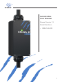
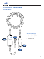
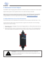
Grizzl-E Mini EV Charger is a small, versatile, and portable EV charging station with a NEMA 4 Indoor/Outdoor aluminum cast enclosure. Made in Canada and built for any environment, Grizzl-E Mini provides up to 10kW of power to your vehicle and can be set to multiple current ratings for 240V and 120V outlets. The Grizzl-E Mini Edition has easy-to-adjust smart features to change settings for different charging locations, monitor the charger, and set charging schedules.
Here are some of the key features and benefits of the Grizzl-E Mini EV Charger:
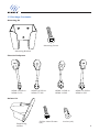
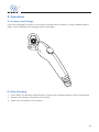
- Compact and portable: The Grizzl-E Mini is small and lightweight, making it easy to transport and store. It's also weatherproof, so you can use it indoors or outdoors.
Grizzl-E Mini EV Charger is a small, versatile, and portable EV charging station with a NEMA 4 Indoor/Outdoor aluminum cast enclosure. Made in Canada and built for any environment, Grizzl-E Mini provides up to 10kW of power to your vehicle and can be set to multiple current ratings for 240V and 120V outlets. The Grizzl-E Mini Edition has easy-to-adjust smart features to change settings for different charging locations, monitor the charger, and set charging schedules.
Here are some of the key features and benefits of the Grizzl-E Mini EV Charger:
- Compact and portable: The Grizzl-E Mini is small and lightweight, making it easy to transport and store. It's also weatherproof, so you can use it indoors or outdoors.


-
 1
1
-
 2
2
-
 3
3
-
 4
4
-
 5
5
-
 6
6
-
 7
7
-
 8
8
-
 9
9
-
 10
10
-
 11
11
-
 12
12
-
 13
13
-
 14
14
-
 15
15
-
 16
16
-
 17
17
-
 18
18
-
 19
19
-
 20
20
-
 21
21
-
 22
22
-
 23
23
-
 24
24
-
 25
25
-
 26
26
-
 27
27
-
 28
28
-
 29
29
-
 30
30
-
 31
31
-
 32
32
-
 33
33
-
 34
34


Grizzl-E Mini EV Charger User manual
- Category
- Networking
- Type
- User manual
Grizzl-E Mini EV Charger is a small, versatile, and portable EV charging station with a NEMA 4 Indoor/Outdoor aluminum cast enclosure. Made in Canada and built for any environment, Grizzl-E Mini provides up to 10kW of power to your vehicle and can be set to multiple current ratings for 240V and 120V outlets. The Grizzl-E Mini Edition has easy-to-adjust smart features to change settings for different charging locations, monitor the charger, and set charging schedules.
Here are some of the key features and benefits of the Grizzl-E Mini EV Charger:
- Compact and portable: The Grizzl-E Mini is small and lightweight, making it easy to transport and store. It's also weatherproof, so you can use it indoors or outdoors.
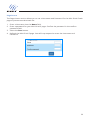
Ask a question and I''ll find the answer in the document
Finding information in a document is now easier with AI
Related papers
-
Grizzl-E Grizzl-E ChargeLab App User manual
-
 Grizzl-E GRIZZL-E GRS-14-24-AW Smart Avalanche Edition EV Charger User manual
-
Grizzl-E DUO EV Charger User manual
-
 Grizzl-E GRIZZL-E GR1-6-24-R Electric Vehicle Charger User manual
-
 Grizzl-E GRIZZL-E GR1-6-18-R Electric Vehicle Charger User manual
-
Grizzl-E GRIZZL-E GR1-6-18-R EV Charger Installation guide


Other documents
-
 EVOCHARGE LIT0244-0522 Level 2 EVSE Charging Stations User guide
-
 YITAHOME SHMYD-V1 User manual
-
 YITAHOME SHMYD-V1 User manual
-
 Charge Ninja SAI Operating instructions
-
 MASSIMO ELECTRIC Y480032711 User manual
-
Lenz J1772 to User guide
-
Tesla Gen2 Installation guide
-
Hubbell Wiring Device-Kellems PD2820 Installation guide
-
INVT EVC Series User manual
-
LECTRON EVCharge5-15N User manual


