Page is loading ...

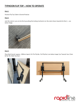
ATTENTION CUSTOMER!
DUE TO SUPPLY CHAIN ISSUES,
WE MADE A COLOR CHANGE TO THE WHEELS
ON YOUR TRAILER THAT MAY NOT BE
REFLECTED IN ADVERTISING OR IMAGERY.
AS THE ORIGINAL ADVERTISED WHEEL
COLOR IS NO LONGER AVAILABLE.
OFFERING THE SAME QUALITY, RELIABILITY,
STABILITY AND SAFETY AS
THE PREVIOUS WHEELS.
THE NEW WHEELS REQUIRE THAT THESE
ATTACHED INSTRUCTIONS ARE FOLLOWED, AND
THE ORIGINALS ARE DISCARDED.
PLEASE FEEL FREE TO
CONTACT US WITH ANY QUESTIONS.
THANK YOU FOR CHOOSING MALONE.


MPG595
MALONE
R
MALONE
R
*ATTENTION CUSTOMERS*
Thank you for your recent purchase of a Malone trailer.
Please inspect all parts and hardware bags prior to assembly.
*Important documents may come directly from the dealer
you’ve purchased the trailer from.
** IF your trailer includes a large red envelope
(found in the axle box), place the envelope containing
important documents is a safe spot.
parts are missing - please email us with photos and your Proof
of Purchase at:
Email:[email protected]
For the most updated instruction manual, please visit:
maloneautoracks.com/dealerimages/pdf/MPG595.pdf
Thank you from all of us at Malone

Important Note
Product Warranty & Registration Form
All information is condential and used exclusively by MALONE only.
MALONE
R
MALONE AUTO RACKS 81 County Rd. Ste 1, Westbrook, ME 04092
P: 207.774.9100 F: 207.615.0551
E: support@maloneautoracks.com W: www.maloneautoracks.com
Dear Customer,
Thank you for your purchase of a Malone Product.
In order to be eligible for the Malone Warranty program, we ask that you contact us online at the link provided
below: With-in 30 days of purchase. You can also mail this letter back to the address at the bottom.
• Online: https://maloneautoracks.com/product-registration.php
We will require the information below.
Here is the information collected:
First Name:
Last Name:
Address:
Address2:
City:
State:
Zip:
Country:
Email:
Phone:
Product Description/Name:
Product MPG#
Date Purchased:
Store Where Purchased:
Purchase Price:
Thank you for choosing Malone!

800-295-0042 ext 206
MPG460XT
Take a few moments and read through these instructions to familiarize yourself
with the step by step assembly process before you begin turning wrenches.
Unpack and sort the components into groups as shown in the following pages.
Then assemble each group in order. Lets get started !!
Required Tools:
• (2) 3/4” wrenches • (2) 9/16” wrenches (a deep socket is recommended)
• Large fl at blade screw driver • (1) 7/16” wrench
• Razor knife • Pliers
• Wire stripping tool • Electrical connector crimping tool
• Lug wrench • Small hammer
Visit us at maloneautoracks.com
for more fi ne products and accessories.
Malone MicroSport Trailer
Model MPG460XT Assembly Instructions
TM
REV 2
MPG595
Malone LowMaxTM Trailer
Model MPG595 Assembly Instructions
MALONE
R
MALONE
R
1

Visit www.maloneautoracks.com/Replacement-Parts
for all of your spare part needs
MPG595
Group 1: Tongue & Frame Components
Group 2: Axle / Spring Components
MPG525G
800-295-0042 ext 206
2
Group 1:
Frame
Components
Bag 11430
Group 2:
Axle / Spring Components Bag 11432
Main Frame
Tongue Frame
2

Group 3: Lighting Components
800-295-0042 ext 206
MPG460G
1. Installing the ground wire con-
nector. Strip 3/8” of insulation off the
white ground wire and crimp on the
ring connector as shown.
2. Assemble the tongue skid and safety chain assembly
with a 3/8” x 1-1/2” bolt as shown. Use washers above
and below the chain ends.
COUPLER ASSEMBLY
(Group 5)
Visit www.maloneautoracks.com/Replacement-Parts
for all of your spare part needs
MPG595
Group 4: Fender Components
Group 5: Coupler Components
3

MPG525G
800-295-0042 ext 206
4
FRAME ASSEMBLY (Group 1)
Group 6:
Load Bar
Components
Bag 11433
2. Get the wiring harness out of the
light kit. Un-kink the last 6 feet of
the 20 foot harness. Un-kink the
entire 4 foot harness. Wrap the 2
ends of the long harness together
with electrical tape.
4. Pass the entire harness through the grommet and out the top of
the tongue as shown.
3. Stand the front tongue section
on end with the coupler holes up.
Push a wire protection grommet
into the wiring harness hole as
shown.
1. First we will build the 2 piece tongue. The middle of the
tongue has symmetrical holes for the joining plates. The
forward end of the tongue has holes for the coupler.
Load Bars (2) and Brackets (4)Load Bars Support Tubes (4)
Group 6: Load Bar Components
MPG525G
800-295-0042 ext 206
4
FRAME ASSEMBLY (Group 1)
Group 6:
Load Bar
Components
Bag 11433
2. Get the wiring harness out of the
light kit. Un-kink the last 6 feet of
the 20 foot harness. Un-kink the
entire 4 foot harness. Wrap the 2
ends of the long harness together
with electrical tape.
4. Pass the entire harness through the grommet and out the top of
the tongue as shown.
3. Stand the front tongue section
on end with the coupler holes up.
Push a wire protection grommet
into the wiring harness hole as
shown.
1. First we will build the 2 piece tongue. The middle of the
tongue has symmetrical holes for the joining plates. The
forward end of the tongue has holes for the coupler.
D-Rings (4)
Visit www.maloneautoracks.com/Replacement-Parts
for all of your spare part needs
TONGUE & FRAME ASSEMBLY (Group 1)
2. on its back to make
it easier to install the tongue, springs and axle. Once
the tongue, springs and axle assembly are installed
hangers. See image 3.
nylon lock nut. Hand Tighten Only. See image 1.
Adjust as needed and fully secure the 4 corners along the top side. See image 2.
Front
rear
1 2
3
4

Coupler / Hitch End
See image 4.
1
23
4 5
5

member, use a washer under the bolt
head, nut and washer inside the cross
tighten. See image 6.
6
7 8
9
6

MALONE
R
7
MALONE
800-295-0042 ext 206
MPG525G
17. Lay the tongue onto the frame, with the MALONE logo upside down. Support
the end of the tongue so it lays nearly fl at on the front and mid cross members.
18. Install the long 1/2” bolt through the front cross member, (washer under the bolt head), nut inside
the cross member
and fi nger tighten.
Install the short 1/2”
bolt inside the end of
the tongue, (washer
under the bolt head),
nut inside the cross
member and fi nger
tighten.
19. Fully tighten all
12 carriage bolts.
Then fully tighten
the two 1/2” tongue
mounting bolts.
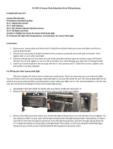
SPRING AND AXLE ASSEMBLY
(Group 2)
1. Set the envelope containing the manufacturer’s certifi cate of
origin (MCO) and VIN labels aside in a safe place.
2. Find the side of the axle
with the spring centering
holes. These holes mate
with the spring center stud.
4. Run each nut down UNTIL IT NEARLY TOUCHES
THE PLATE ONLY! DON’T FULLY TIGHTEN NOW!!
You may need to wiggle the springs to fi t them into the
spring brackets in the next step.
SPRING & AXLE ASSEMBLY (Group 2)
1. Set the large red envelope (in the axle box) containing
important documents in a safe spot.
2. Spin the axle to nd the side with the spring centering holes.
These holes mate with the spring
center stud.
3. Lay the springs on top the axle
with the centering studs in the
holes in the axel. Then assemble
the U-bolts, tie plates and nuts as
shown. Make sure both springs
are facing the same way!
4. Run each nut down UNTIL IT
TOUCHES THE PLATE ONLY! DON”T TIGHTEN!!
You will need to wiggle the springs to t them into the
spring brackets in the next step.
5. Lift the axle/spring assembly to the trailer frame and slide the slipper spring ends into the slipper spring
brackets. Then let the spring eyes down into the front hangers
6. Install the shackle bolts with
the nuts to the inside and tighten
until rm. Do not over tighten
which would bend the spring
hanger in and pinch the spring.
7. Fully tighten the 4 front spring
hanger mounting bolts.
8. Fully and evenly tighten the 8
axle U-bolts.
MPG525G
800-295-0042 ext 206
8
5. Lift the axle/spring assembly to the trailer frame and slide the slipper spring ends into the slipper
spring brackets. Then let the spring eyes down into the front hangers.
6. Install the shackle bolts with the nuts to the inside and
tighten until fi rm. Do not over tighten which would bend
the spring hanger in and pinch the spring.
7. Fully tighten the 4 front spring hanger mounting bolts.
8. Fully and evenly tighten the 8 axle U-bolts.
10. Lift the trailer at one rear corner
and roll it over onto the tires.
ALWAYS BEND FROM YOUR KNEES
WHEN LIFTING. IF THE TRAILER
IS TOO HEAVY FOR YOU TO FLIP
SAFELY RECRUIT SOME FRIENDS
TO ASSIST YOU.
11. Tighten the lug nuts fi rmly, to 75 to
85 foot pounds of torque.
9. Install the wheels on the hubs with
valve stems facing out and install and
fi nger tighten the lug nuts.

LIGHT ASSEMBLY (Group 3)
with the light kit. *Making sure to Attach/secure the license plate
amber side lights. First, push the wire leads through the lower right
hole and the lamp stud
through the center hole.
4. Secure with the lamp
the other side.
NOTE: Tapered end
on lug nut goes towards rim.
ALWAYS BEND FROM YOUR KNEES WHEN LIFTING. IF THE
TRAILER IS TOO HEAVY FOR YOU TO FLIP SAFELY RECRUIT
SOME FRIENDS TO ASSIST YOU.
*T ?

connections and plug-in matching colored leads/wires. Repeat with all remaining lights and use the
remaining wire clips as needed.
as shown.
towards the rear tail lights.
to secure the wires between the cross members.
9
running lights and the tail lights.
These color coated wires should match the connections at your lights.
REFERENCE:
Trailer Wiring Color Code
•Brown = running lights
•Yellow = driver turn / driver brake
•Green = passenger turn / passenger brake
•White = ground
1. Sandwich the license plate mounting bracket
between the driver side lamp and the frame. Use the nuts
provided with the lamp kit.
3. Check that the wiring harness outside
the tongue grommet at the coupler is still
full length and did not pull into the tongue.
4. Route the GREEN/BROWN wire along
the passenger’s side of the frame. Route the
YELLOW/BROWN wire along the driver’s side. Install wire
clips beside the tongue and clip the wires.
5. Route each harness around the
corner to the side marker light. Note
where you will connect the side marker
wire. Lift the harness on top of the
frame. Pierce the knife tip between the
wires, PULL only about 1/2” of wire past
the blade, then use your fi ngers to pull
2-3 inches of wire apart.
2. Install side marker lights at the 2 holes in the front of the side
rails. One hole for the bolt, one hole for the
wire. Use the nuts provided with the lamp kit.
6. Press the brown wire into the quick connector as shown. Then
insert the wire from the side marker
light fully into the 2nd opening. Use
pliers to squeeze the conductor blade
down and through the insulation. The
blade cuts through the insulation and
connects the wires inside. Flip the
cover to lock the connector. Repeat on
the other side again using the brown
wire.

COUPLER ASSEMBLY (Group 5)
2. Place the skid and chain assembly under the tongue and insert the bolt up through the skid bolt hole on
lock nut.
800-295-0042 ext 206
MPG460G
1. Installing the ground wire con-
nector. Strip 3/8” of insulation off the
white ground wire and crimp on the
ring connector as shown.
2. Assemble the tongue skid and safety chain assembly
with a 3/8” x 1-1/2” bolt as shown. Use washers above
and below the chain ends.
COUPLER ASSEMBLY
(Group 5)
FENDER ASSEMBLY (Group 4)
tighten all 8 screws and nuts.
Note:
Note that when bolting the mounting
under the nut.
as shown. Secure with nylon nuts. Place
washer under nut.
10

LOAD BAR ASSEMBLY (Group 6)
install the two small bolts / nuts through each bracket trapping the load
bars inside the brackets.
support tube.
6. Center the load bars to the trailer, then tighten all 8 bracket bolts.
tubes, one in each corner.
the nylon lock nuts.
remaining 3 support
tubes.
11

MPG525G
800-295-0042 ext 206
12
2. Use a small hammer or block of wood
to install the end plugs into both ends of all
four load bar support tubes.
3. Install the load bar support tubes onto
the outer most pair of holes in the front
and rear cross member and fully tighten.
4. Install the load bars and brackets onto the load bar
supports. Center the load bars and fully tighten all load
bar bolts.
5. Use a small hammer or block of wood to install the
end caps onto the load bars.
Apply the TIRE AND LOADING Decal and the VIN Decal as shown below onto the driver side
of the frame. Be sure to clean the frame before applying the decals.
Visit us at maloneautoracks.com
for more fi ne products and accessories.
Your XtraLight Trailer is now complete and ready to register and title !
Contact your local DMV offi ce for specifi c procedures in your State.
TM
PLEASE REFERENCE YOUR RED ENVELOPE
W
Your Malone LowMaxTrailer is now
complete and ready to register and title!
F Tongue F
the joining plates.
tongue with the small hanger bracket on the joining
plate.

MALONE AUTO RACKS 81 County Rd. Ste 1, Westbrook, ME 04092
P: 207.774.9100 F: 207.615.0551
E: support@maloneautoracks.com W: www.maloneautoracks.com
Limited Five (5) Year Warranty
The Malone Auto Racks (Malone) Limited 5 Year Warranty covers certain Malone-brand products that have been specically
identied for inclusion in the program. This warranty is in eect for ve (5) years, from the time of sale, for the original retail purchaser
of the product. This warranty is terminated after ve years from the date of purchase, or, when the original retail purchaser sells or
otherwise transfers the product to any other person or entity during the ve year warranty period.
Subject to the limitations and exclusions described in this warranty, Malone will remedy defects in materials and/or workmanship
by repairing or replacing, at its option, a defective product without charge for parts or labor. Malone may elect, at its option, not to
repair or replace a defective product but rather issue to the original retail purchaser a refund equal to the purchase price paid for the
product, or credit to be used toward the purchase of a replacement Malone product.
This warranty does not cover, and no warranty is given for defects or problems caused by normal wear and tear, which includes,
but is not limited to, surface (aesthetic) metal corrosion, scratches, dents, deformities, accidents, unlawful vehicle operation, or any
modication of a product not performed or authorized in writing by Malone.
In addition, this warranty does not cover problems resulting from conditions beyond Malone’s control including, but not limited to,
theft, misuse, overloading, or failure to assemble, mount or use the product in accordance with Malone’s written instructions or
guidelines included with the product provided to the original retail purchaser.
No warranty is given for Malone products purchased outside of the continental United States, Canada and Mexico.
If the product is believed to be defective, the original retail purchaser should contact the Malone dealer from whom it was purchased,
who will give the original retail purchaser instructions on how to proceed. If the original retail purchaser is unable to contact the
Malone dealer, or the dealer is not able to remedy the defect, the original retail purchaser should contact Malone by email at
In the event that the product must be returned to Malone, a technician at the email address above will provide the original purchaser
with return shipping instructions. The original purchaser will be responsible for the cost of mailing the product to Malone. In order
to be eligible to receive any remedy under this warranty, a copy of the original purchase receipt, a description of the defect and a
return address must be provided.
Disclaimer of Liability
Repair or replacement of a defective product, or the issue of a refund or credit (as determined by Malone) is the original retail
purchaser’s sole and exclusive remedy under this warranty. Damage to original purchaser’s vehicle, cargo, or property, and/ or to
any other person or property is not covered by this warranty.
This warranty is expressly made in lieu of any and all other warranties, express or implied, including the warranties of merchantability
and tness of a particular purpose
Malone’s sole liability to any purchaser is limited to the remedy set forth above. In no event will Malone be liable for any direct,
indirect, consequential, incidental, special, exemplary, or punitive damages , or, for any other damages of any kind or nature
(including but not limited to, lost prots, lost income or lost sales).
Some states do not allow the exclusion or limitation of incidental or consequential damages, so the above limitations may not be
applicable.
In addition, all vehicular transports are potentially hazardous. Any person(s) using Malone products are personally responsible for
following the given directions for use and/or installation and accepts full responsibility for any and all damages or injury of any kind
including death, which may result from their use and/or installation.
MALONE
R
/