CYP CDPS-U10H2HFS Operating instructions
- Category
- Video switches
- Type
- Operating instructions
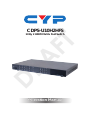
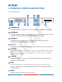
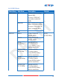
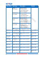
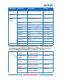
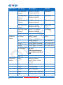
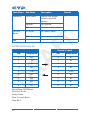
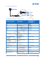
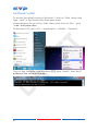
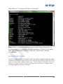
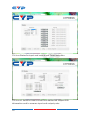
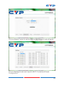
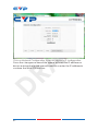
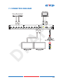
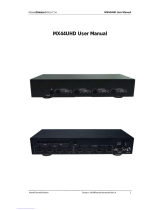
CYP CDPS-U10H2HFS is an advanced HDMI Matrix Switch that allows you to connect up to 10 HDMI sources to two HDMI displays simultaneously. It supports 4K2K and 1080p resolutions and is compatible with 3D and deep color. The matrix switch also supports various audio formats, including LPCM, Dolby Digital, and DTS. You can control the switch using the front panel buttons, the included remote control, or through RS-232, Telnet, or Web GUI.
CYP CDPS-U10H2HFS is an advanced HDMI Matrix Switch that allows you to connect up to 10 HDMI sources to two HDMI displays simultaneously. It supports 4K2K and 1080p resolutions and is compatible with 3D and deep color. The matrix switch also supports various audio formats, including LPCM, Dolby Digital, and DTS. You can control the switch using the front panel buttons, the included remote control, or through RS-232, Telnet, or Web GUI.


-
 1
1
-
 2
2
-
 3
3
-
 4
4
-
 5
5
-
 6
6
-
 7
7
-
 8
8
-
 9
9
-
 10
10
-
 11
11
-
 12
12
-
 13
13
-
 14
14
-
 15
15
-
 16
16
-
 17
17
-
 18
18
-
 19
19
-
 20
20
-
 21
21
-
 22
22
-
 23
23
-
 24
24
-
 25
25
-
 26
26
-
 27
27
-
 28
28
-
 29
29
-
 30
30


CYP CDPS-U10H2HFS Operating instructions
- Category
- Video switches
- Type
- Operating instructions
CYP CDPS-U10H2HFS is an advanced HDMI Matrix Switch that allows you to connect up to 10 HDMI sources to two HDMI displays simultaneously. It supports 4K2K and 1080p resolutions and is compatible with 3D and deep color. The matrix switch also supports various audio formats, including LPCM, Dolby Digital, and DTS. You can control the switch using the front panel buttons, the included remote control, or through RS-232, Telnet, or Web GUI.
Ask a question and I''ll find the answer in the document
Finding information in a document is now easier with AI
Related papers
Other documents
-
 Cypress CMSI-8H8HS Operating instructions
-
 Paugge ENT-VWMXS20B8X8 User manual
-
 infobit iMatrix H88HAW User manual
-
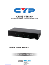 Cypress CPLUS-V4H1HP Operating instructions
-
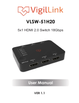 VigilLink VLSW-51H20 User manual
-
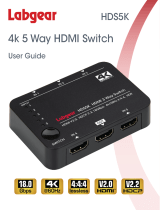 Labgear HDS5K User guide
-
 C4i HDMX02 User manual
-
 HomeCinemaSolution MX44UHD User manual
-
HDMI 1.4 Matrix User manual
-
MyCableMart HD-M-962U User manual


