Page is loading ...

Part No. X39640529-02
Since the Trane Company has a policy of continuous product improvement, it reserves the right to change
specifications and designs without notice. The installation and servicing equipment referred to into this book-
let should be done by qualified experienced technicians.
Installation CLCH-IN-18A
Library Service Literature
Product Section Air Handling
Product Central Station Air Handlers
Model T-Series Climate Changer
Literature Type Installation
Sequence 01
Date June 1999
File No. CLCH-IN-18A 6/99
T-Series Climate
Changer
®
Roof Curb

ii RTWA-IOM-1A

Installation 1
GENERAL
Roof curbs can be used with T-Series Climate
Changers of all sizes and configurations.
Before proceeding with the installation, identify the T-
Series unit sections by the nameplate labels on the
unit, typically as shown in
Figure 1
:
Figure 1
Unit Nameplate
The as-built submittals show the intended layout of
the various unit sections to meet job site
requirements. For exact information, always refer to
specific unit submittals that can be obtained from the
local Trane sales office.
Installation information (especially unit dimensions,
curb section location and roof opening locations)
may vary with special equipment and applications.
For exact information, always refer to specific unit
submittals.
Roof curbs for the Trane T-Series Climate Changer
units are shipped “knocked down” for assembly at
the job site.
INSTALLATION CONSIDERATIONS
Before assembling or placing the roof curb in
position, consider the following for a proper
installation:
q Units with special options or arrangements will
differ in dimensions, clearances, weights and roof
opening dimensions and locations. Refer to
specific unit and roof curb submittals before
marking off the dimensions of the unit roof curb,
pipe cabinet roof curb (if pipe cabinet is ordered)
and roof openings.
q The installation of the roof curb requires mounting
on a flat surface so that the unit may be set level.
This is necessary to ensure proper operation and
coil condensate drainage.
q Isolation rails should not be installed on top of
Trane roof curbs. If isolation rails or isolation
curbs are required, then the whole curb system
should be supplied by a speciality curb company.
q Adequate space must be available for
maintenance and free air clearances. See job site
submittals for dimensions.
q The roof must be capable of adequately
supporting the weight of the T-Series Climate
Changer, its accessories and the roof curb. Refer
to CLCH-IM-16 to obtain overall unit weight. For
roof curbs supplied by Trane, the approximate
roof curb weight is 9.8 lb per linear foot.
Documentation that accompanies your Trane-
ordered roof curb will list the exact roof curb
weight.
q The roof curb must be supported along its entire
perimeter. The curb may be set parallel or at right
angles to roof support members. If at right angles
to the support members, there must be adequate
supporting roof cross members between the ends
(in the direction of airflow). Be sure the cross
members do not interfere with the connection of
supply and return ducts to the unit. See
Figure 2
for details.
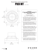
q If a unit is pier-mounted, as a minimum, locate
one pier at each corner, directly underneath any
shipping split (ensure full support under each
side), and then every four feet at equally spaced
intervals around the perimeter of the unit. Both the
unit and the pipe cabinet should be supported by
their base channel around the entire perimeter
(see
Figure 3
and
Figure 4
).
q
For new building construction
, the roof curb may
be installed as soon as the roof support members
are in place. Trane recommends that the roof curb
be placed directly on the roof support members
and welded into place. If the curb is mounted on
the roof deck, additional support is necessary
directly below the curb flanges to minimize
vibration.
Figure 5
and
Figure 6
show typical roof
curb installations.
q The roof curb should be assembled at the most
convenient spot near the point of installation. For

2 CLCH-IN-18A
existing buildings, hoist the container to the roof
for assembly. Refer to the Assembly and
Installation section.
q Place gasketing on top of the roof curb and along
the entire perimeter of the roof curb as a seal
between the roof curb and unit base.
q Follow all local building codes and accepted
roofing practices when installing the curb.
Figure 2
Unit Set Perpendicular to Roof Curb Members
Figure 3
Pier Mount Detail
Figure 4
Unit Supports for Pier Mounts
Figure 5
Typical Installation of Roof Curb in Old Construction
Figure 6
Typical Installation of Roof Curb in New Construction
Auxiliary support
Roof mounting curb
Inside edge
Main roof support member
located under center of unit
loaded under curbs
or auxiliary support
or under section joints
Main roof support
member capable of
supporting unit weight
AIR FLOW
Intake
Discharge
Piers
4’ TYP
2x4 nailer
Roof curb
Wooden nailer
Gasket
Nail
Flashing
4x4 cant
Roof insulation
Roof deck
Roof structure
Counter flashing
Roof/insulating mat’l
2x4 nailer
Roof curb
Counter flashing
Flashing
4x4 cant
Roof insulation
Roof deck
Roof structure
Gasket
Nail
Roof/insulating mat’l
See
Figure 7 Detail
roofcurb.fm Page 2 Wednesday, September 1, 1999 12:37 PM

Installation 3
Figure 7
Detail of Figure 6
NOTE: MATERIALS TO ATTACH TO THE ROOF CURB
ARE TO BE SUPPLIED BY THE INSTALLER. GASKET
AND 2 X 4 NAILER ARE SUPPLIED BY TRANE.
DO NOT OVERLAP COUNTER FLASHING OVER THE
TOP OF THE ROOF CURB. COUNTER FLASHING
SHOULD EXTEND TO THE BOTTOM OF THE ROOF
CURB DRIP LIP. ATTACH COUNTER FLASHING WITH
FASTENER THROUGH THE WOODEN NAILER
ASSEMBLY AND INSTALLATION
The following procedure explains how to assemble
and install roof curbs provided by the Trane
Company. An attachment specific to your roof curb is
shipped with your Trane-ordered roof curb.
Figure 8
Typical roof curb provided by Trane.
NOTE: FOR SPECIALTY OR FIELD FABRICATED
ROOF CURBS PLEASE SEE THE SECTION ENTITLED
SPECIALTY ROOF CURBS FOR IMPORTANT
INFORMATION.
1 Attach cross brace and outer side splice plates at
splice locations
(Figure 9)
.
Figure 9
Side Splice Detail
2 Attach outer and inner corner splice plates (4
places)
(Figure 10)
.
Figure 10
Corner Splice Detail
3 Tighten nuts/bolts at all locations. Ensure lock
nuts are securely tightened.
4 Check curb dimensions
(Figure 11)
.
Figure 11
Unit Roof Curb Perimeter
Check squareness of curb. Measurements from A-B
should equal measurement from C-D (± 1/8”).
2 x 4 Nailer
Roof curb
Gasket
Nail
Counter
Flashing
Roofing/insulating
mat’l
flashing
Nut
Bolt
Washer
Cross brace
Splice plate
Washer
Inner corner angle
Outer corner angle
Roof curb
Nut
Washer
Bolt
Washer
A
B
C
D

4 CLCH-IN-18A
NOTE: MEASUREMENTS A-C, D-B, A-D, AND B-C ARE
INSIDE CURB DIMENSIONS AND ARE SUPPLIED WITH
THE UNIT SPECIFIC ROOF CURB MANUAL.
5 Assemble the pipe cabinet roof curb (when
supplied). See
Figure 12
. Self-drill to unit roof
curb wall.
NOTE: IF PIPE CABINET ROOF CURB INTERFERES
WITH SPLICE PLATES, FIELD DRILL HOLES TO
MATCH THOSE IN THE SPLICE PLATE. ATTACH THE
PIPE CABINET ROOF CURB WITH SPLICE PLATE
BOLTS. SELF-DRILL THE OTHER END.
Figure 12
Pipe Cabinet Roof Curb Assembly
IMPORTANT: IF A PIPE CABINET IS USED, THE
GUTTER MUST BE INSTALLED. THIS GUTTER IS A
WATER MANAGEMENT FEATURE TO PREVENT
WATER FROM ENTERING THE PIPE CABINET.
6 Install the gutter. A gutter
(Figure 13)
, ships with
the roof curb assembly if a pipe cabinet roof curb
is ordered.
(a)
Remove paper backing from the butyl tape and
set the gutter piece on the pipe cabinet roof
curb as shown in
Figure 13
. Ensure that the
butyl tape is providing a good seal.
(b)
Attach the pipe cabinet roof curb to the unit’s
roof curb with self drilling screws.
(c)
Attach the gutter to the unit roof curb nailer
with screws through the existing holes in the
gutter.
(d)
Install gasket along the perimeter of the pipe
chase roof curb and the gutter as shown in
Figure 13
. The gasket for the gutter will run
along the flat surface of the gutter which rests
on the pipe chase roof curb. This may be done
before or after placing gasketing along the
perimeter of the unit roof curb. Gasketing is
provided with the roof curb when ordered from
Trane.
Figure 13
Gutter Installation
5 Install the curb. The curb may be set on structural
framing (by others). This curb is designed to
transfer the load to a continuous underlying
structural frame. The structural members (by
others) should span the perimeter of the curb.
WARNING
Make certain that the curb span
joist space is supported. Failure to
do so can result in severe per-
sonal injury or death or equipment
damage.
Figure 14
Roof Curb
SPECIALTY ROOF CURBS
Units to be mounted on a roof curb not supplied by
Trane require special attention, especially if a pipe
cabinet is ordered from Trane. A typical unit roof curb
and unit base cross-section without a pipe cabinet is
shown in
Figure 14
.
Table 1
lists the outside-to-
outside dimensions for over all width and length of
Unit roof curb
2x4 nailer
Roof curb angle
Pipe chase roof curb
Gutter Not Shown
Notched for gutter
and unit joint
Gutter
Pipe chase roof curb
Unit roof curb
Gasket (4 edges)
Flashing on outside of curb

Installation 5
the roof curb for each size unit. Length is dependent
on the various unit options ordered. Refer to
submittals for module lengths.
NOTE: CENTER THE UNIT BASE ON THE ROOF CURB.
Figure 15
Cross Sections
Table 1
Specialty Roof Curb Dimensions
Where Lm is the sum of all module lengths in the unit. Lm does
not include the 3 inches for each end of the unit base.
Pipe cabinets ordered from Trane for field installation
require special attention with regard to joining the
unit roof curb and pipe cabinet roof curb. A good joint
will prevent any water management problems within
the pipe cabinet.
q The pipe cabinet roof curb should be three-sided
and have dimensions as shown in
Figure 16
, a
top view of the pipe cabinet roof curb, and
Table 2
respectively. Dimension ‘L’ is from the outside of
the unit roof curb to the outside of the pipe cabinet
roof curb. Dimension ‘X’ is the outside-to-outside
width dimension of the pipe cabinet roof curb.
Dimension ‘Z’ locates the pipe chase roof curb
along the unit roof curb in the direction of airflow.
This measurement is from the outside of the unit
roof curb to the outside of the pipe cabinet roof
curb. The basic formula becomes
Z = LDM – 1
where LDM is the total length of the modules
downstream of the pipe cabinet including the 3-
inch end of the unit base.
Figure 16
Top View of Unit and Pipe Cabinet Roof Curbs
UNIT SIZE Width Length
336 Lm + 5
649 Lm + 5
853 Lm + 5
10 65 Lm + 5
12 69 Lm + 5
14 73 Lm + 5
17 79 Lm + 5
21 81 Lm + 5
25 83 Lm + 5
30 96 Lm + 5
35 101 Lm + 5
40 114 Lm + 5
50 125 Lm + 5
1.945
3.00
Size 3-30 = 4 in
Size 35-50 = 6 in
Size 66-100 = 8 in
Unit Base
2 in
1 in
14 in
3 in
Unit Roof Curb
66 140 Lm + 5
80 140 Lm + 5
100 155 Lm + 5
Pipe chase
roof curb
X
L
Unit roof curb
Z

6 CLCH-IN-18A
Table 2
Pipe Chase Roof Curb Dimensions
Lp is the sum of the module length(s) covered by the pipe cabinet.
Refer to submittal.
q The height of the pipe chase roof curb should be
1.75 inches less than the height of the unit roof
curb. See
Figure 17
.
q The pipe cabinet roof curb will need to be notched
in order to install a special gutter piece.
Figure 17
shows a dimensioned detail of the pipe cabinet
roof curb being installed to the unit roof curb.
Please note the notched section to get the
dimensions. Refer to Step 6 of
Assembly and
Installation Instructions
section for more
information on installing the gutter piece.
Figure
18
shows the pipe cabinet and gutter coming
together and assembling to the pipe cabinet roof
curb.
Figure 17
Detailed Notching
Figure 18
Assembly
q
Figure 19
shows a right side view and isometric
view of a fabricated gutter piece with detailed
dimensions.
L Dimension
Unit size Reduced Standard Extended
3-30
17.50 33.00 48.50
35-40
18.00 34.00 50.00
50-100
21.00 40.00 54.50
Unit Sizes 3-100
X Dimension
Reduced
Lp + 1.125
Standard
Lp + 1.125
Extended
Lp + 1.125
Pipe chase
roof curb
Gutter
Unit
roof
curb
1.060
.178
.868
1.750
2.942
3.318

Installation 7
Figure 19
Gutter views
L is the fabricated gutter length. L = Lp + 1.316 inches.
DUCTWORK RECOMMENDATIONS
Sound Attenuation
Noise is produced by unit supply fans, and exhaust
fans. Supply fan noise is substantially attenuated by
the ductwork, provided it is properly constructed.
SMACNA recommendations for metal gauge
thickness and installation should be followed
carefully. Lightly constructed ductwork can produce
“oil canning”--a rapid in-and-out pulsating motion of
the duct walls--resulting in sound problems.
NOTE: IF ROOF DECKING CANNOT BE PLACED
UNDER THE UNIT, AN ACOUSTICAL BARRIER CAN BE
INSTALLED.
Corrugated steel decking is acoustically ideal for the
installation of the roof curb and connecting ductwork.
Closely toleranced holes must be cut in the roof deck
for the supply and return ductwork. When the duct is
installed, caulking must be used to seal the decking
to the duct. Even a small air leak between the duct
and the deck will destroy most of the attenuation
available from the steel decking.
In addition, special consideration may be required to
ensure that the weight of the unit does not crush the
roof deck at those points where the deck is between
the curb and support joist. Poured insulation will
usually add the required strength, while the use of
rigid insulation may require placement of three-inch
support channels on the decking.
As a general rule, exhaust fan noise is not a problem
and can be adequately attenuated by the return
ductwork. For critical applications where return
ductwork is not required, however, installation of an
acoustically-lined “return T” is recommended; see
Figure 20
.
Supply and Return Air Ductwork
Ductwork for all units must be fabricated and
installed by the installing contractor; to ensure proper
duct construction and installation, SMACNA
recommendations should be closely followed.
Below are several typically used guidelines for
ductwork construction:
- Connections to the unit should be made with three-
inch canvas connectors to minimize noise and
vibration transmission;
.625
.926
3.318
2.000
1.500
L
.658
.625
Last Module
2nd Module
1st Module
.658
2.15
2.15

8 CLCH-IN-18A
- Elbows with turning vanes or splitters are
recommended to minimize air noise and resistance;
- The first elbow in the ductwork leaving the unit
should be no closer than 3 fan diameters from the
unit, thereby minimizing noise and resistance.
In those instances where the unit is installed over an
acoustically critical area, additional treatment of the
ductwork is recommended. Both supply and return
ductwork should be lined internally with glass fiber
duct liner 1” thick. The external surface of the supply
duct should be covered with an acoustical barrier
material such as one or two pound/sq. ft. sheet lead
(1/64” or 1/32”) or loaded vinyl sheet or gypsum
board for the first 10 ft. of ductwork. The lining should
extend from the point where the duct penetrates the
roof to a distance of 10 ft. beyond the vertical drop
from the unit.
Figure 20
Typical Supply and Return Ductwork
3 Fan
diameters
Return air
Vertical
discharge
Coil
space
Use line duct for all returns
(1” thick, 6 lb density fiberglass recommended)
/