Outdoor Thermostat Field Installation for 13 & 14 SEER Heat Pumps
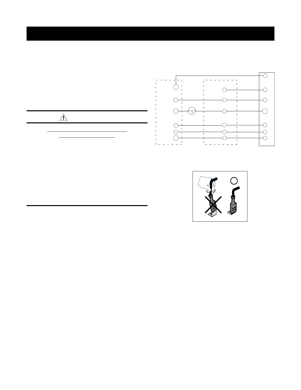
Thermostat
Red
White
Black
Air Handler
Outdoor
Heat
Pump
OUT
IN
R
W
C
O
Y
R
G
C
O
Y
O
C
R
W2
W2
Y1
IN
Green
G
W2
E
ODT
IMPORTANT SAFETY INFORMATION
INSTALLER: Please read all instructions before servicing
this equipment. Pay attention to all safety warnings and any
other special notes highlighted in the manual. Safety markings
are used frequently throughout this manual to designate a
degree or level of seriousness and should not be ignored.
WARNING indicates a potentially hazardous situation that if
not avoided, could result in personal injury or death.
WARNING:
ELECTRICAL SHOCK, FIRE OR
EXPLOSION HAZARD
Failure to follow safety warnings exactly could
result in serious injury or property damage.
Improper servicing could result in dangerous
operation, serious injury, death or property
damage.
• Beforeservicing,disconnectallelectricalpower
to the unit.
• Whenservicingcontrols,labelallwiresprior
to disconnecting. Reconnect wires correctly.
• Verifyproperoperationafterservicing.
14 SEER HEAT PUMPS
The instructions listed below describe how to properly
install the outdoor thermostat on 14 SEER heat pumps.
1. Use a wire with ¼” Quick Connect receptacle terminal
on one end and stripped wire at the other end, cut to
a 5” length. Connect the QC terminal to the Outdoor
Thermostat (ODT) and, using a wire nut, connect the
stripped end of the wire to the black wire connected to
the W2 OUT terminal on the Defrost Board.
2. Place a ¼” Quick Connect receptacle terminal to the
field thermostat wire W from the Air Handler. Connect
the QC terminal to the Outdoor Thermostat (ODT).
3. Using a cable tie, bundle the suspended Outdoor
thermostat to the field thermostat wire bundle in the
control box.
INSTALLATION INSTRUCTIONS


