Earth terminal is provided for easier installation. It is not required by the detector head.
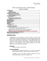
Fyreye Common Base
Part Number: 45681-200GLT
Conventional schematic wiring diagram of detector circuit
ZETA Alarm Systems, Detection House, 72-78 Morfa Road, Hafod, Swansea, SA1 2EN, UK
Tel: (01792) 455175 Fax: (01792) 455176
Addressable schematic wiring diagram of detector circuit
Note: Polarity must be observed on detector as indicated on schematic wiring diagram.
Earth terminal is provided for easier installation. It is not required by the detector head.
From control panel
EARTH
L2
–R
EARTH
L2
–R
EARTH
L2
–R
End-of-line
device
Remote LED
+
–
L1 IN
L1OUT
L
1
IN
L1OUT
L1 IN
L1OUT
Link required for common remote
Positive line
in and out
Negative line
in and out
L2
L1 IN
39214-205/Draft B
EARTH
Earth terminal is provided for easier installation. It is not required by the detector head.
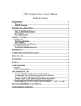
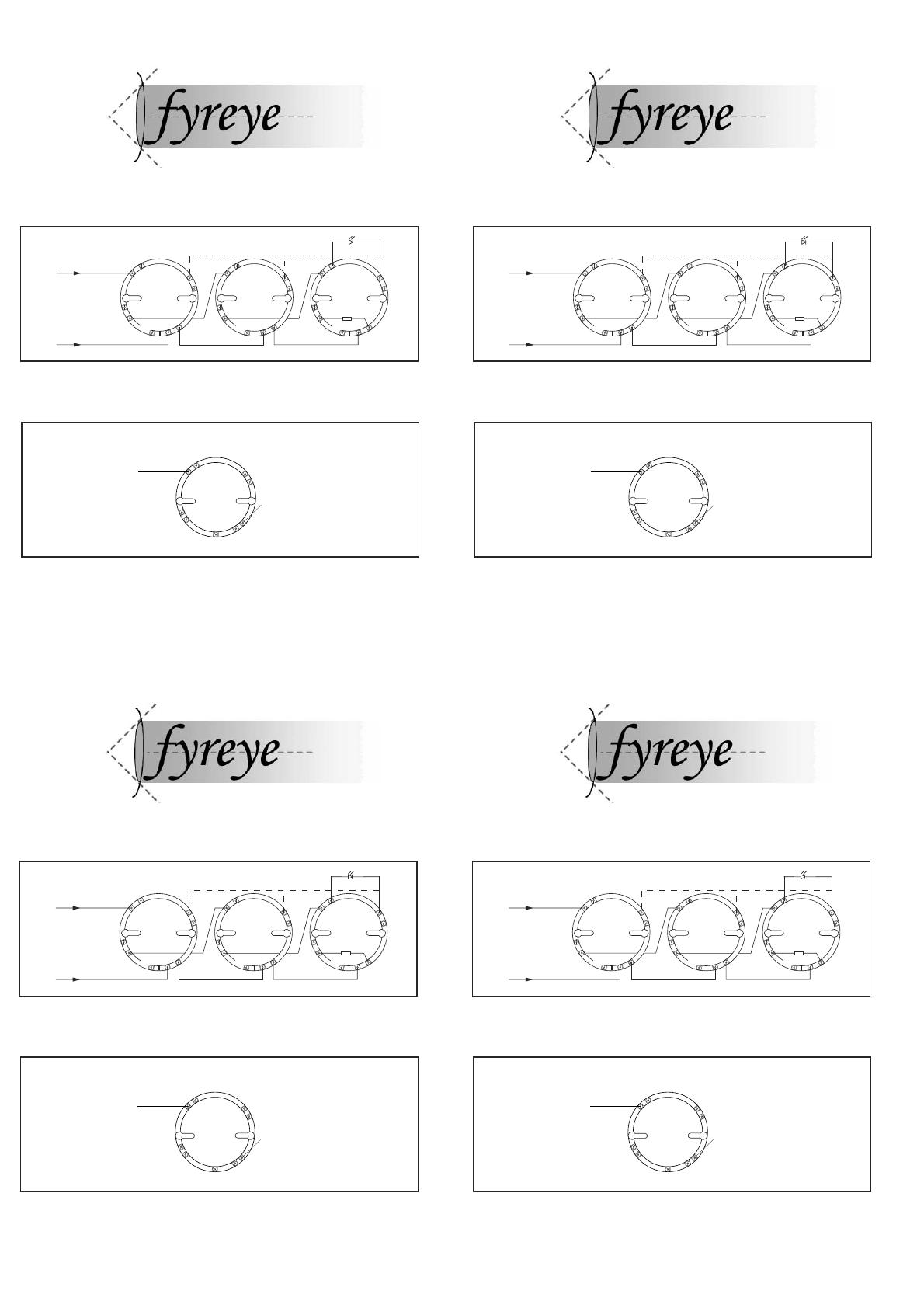
Fyreye Common Base
Part Number: 45681-200GLT
Conventional schematic wiring diagram of detector circuit
ZETA Alarm Systems, Detection House, 72-78 Morfa Road, Hafod, Swansea, SA1 2EN, UK
Tel: (01792) 455175 Fax: (01792) 455176
Addressable schematic wiring diagram of detector circuit
Note: Polarity must be observed on detector as indicated on schematic wiring diagram.
Earth terminal is provided for easier installation. It is not required by the detector head.
From control panel
EARTH
L2
–R
EARTH
L2
–R
EARTH
L2
–R
End-of-line
device
Remote LED
+
–
L1 IN
L1OUT
L
1IN
L1OUT
L1 IN
L1OUT
Link required for common remote
Positive line
in and out
Negative line
in and out
L2
L1 IN
39214-205/Draft B
EARTH
Earth terminal is provided for easier installation. It is not required by the detector head.
Fyreye Common Base
Part Number: 45681-200GLT
Conventional schematic wiring diagram of detector circuit
ZETA Alarm Systems, Detection House, 72-78 Morfa Road, Hafod, Swansea, SA1 2EN, UK
Tel: (01792) 455175 Fax: (01792) 455176
Addressable schematic wiring diagram of detector circuit
Note: Polarity must be observed on detector as indicated on schematic wiring diagram.
Earth terminal is provided for easier installation. It is not required by the detector head.
From control panel
EARTH
L2
–R
EARTH
L2
–R
EARTH
L2
–R
End-of-line
device
Remote LED
+
–
L1 IN
L1OUT
L
1IN
L1OUT
L1 IN
L1OUT
Link required for common remote
Positive line
in and out
Negative line
in and out
L2
L1 IN
39214-205/Draft B
EARTH