1. Center the pipe, cable or conduit in wall
opening or casing. Make sure the pipe will
be adequately supported on both ends.
LINKSEAL® modular seals are not intended
to support the weight of the pipe.
3. Check to be sure all bolt heads are facing
the installer. Extra slack or sag is normal. Do
not remove links if extra slack exists.
NOTE: On smaller diameter pipe, links may need to
be stretched.
4. Slide belt assembly into annular space. For
larger size belts, start inserting LINKSEAL®
modular seal assembly at the 6 o'clock
position and work both sides up toward the
12 o'clock position in the annular space.
5. LS-200 through LS-315 Using a hand
socket allen head or off-set wrench ONLY,
start at 12 o'clock. Do not tighten any bolt
more than 4 turns at a time. Continue in
a clockwise manner until links have been
uniformly compressed. (Approx. 2 or 3
rotations)
5a.LS-325 through LS-650 Using a hand socket
or off-set wrench ONLY, start at 12 o'clock.
Do not tighten any bolt more than 4 turns
at a time. Continue in a clockwise manner
until links have been uniformly compressed
(Approx. 2 or 3 rotations).
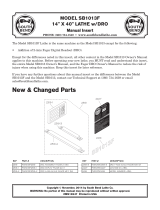
6. Make 2 or 3 more passes at 4 turns
per bolt MAXIMUM, tightening all bolts
clockwise until all sealing elements “bulge”
around all pressure plates. On type 316
stainless steel bolts, hand tighten ONLY
without power tool.
7. If the seal doesn’t appear to be correct
using the instructions provided, call GPT at
1-800-423-2410.
Installation Notes: The LINKSEAL® modular seal bolt heads are usually recessed below the wall opening or the edge of casing pipe and
therefore a socket or offset wrench must be used.
Bulge
Installation Complete
2. Loosen rear pressure plate with nut just
enough so links move freely. Connect both
ends of belt around the pipe.
Connect
LINKSEAL
®
Model
Tool Size/ Type
Req.
Bolt Head
Type
LS-200, LS-275 4mm, Allen
LS-300, LS-315 6mm, Allen
LS-325, LS-340, LS-360 13mm, Hex
LS-400, LS-410, LS-425, LS-475 17mm, Hex
LS-500, LS-525, LS-575 19mm, Hex
LS-615 30mm, Hex
LS-650 19mm, Hex
If the seal doesn’t appear to be correct using the techniques
provided, Call GPT at 1-800-423-2410.
LINKSEAL® Modular Seal - Do's
1. Make sure pipe is centered.
2. Install the belt with the pressure plates evenly spaced.
3. Install the exact number of links indicated in sizing charts.
4. Check to make sure pipe is supported properly during backfill
operations.
NOTE: LINKSEAL® modular seals are not intended to
support the weight of the pipe.
5. Make sure seal assembly and pipe surfaces are free from
dirt.
6. For tight fits, use non-polluting liquid detergent to assist
installation.
LINKSEAL
®
Modular Seal - Don'ts
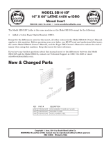
1. Don’t Install the belt with the pressure plates aimed in irregular
directions. (Staggered)
2. Don’t Install LINKSEAL® modular seals where weld-beads or
other irregular surfaces exist without consideration of the
sealing requirements.
3. Don’t torque each bolt completely before moving on to the next.
4. Don’t use high speed power tools (450 rpm or more)
5. Do not use power tools on LINKSEAL® modular seal 316 stainless
steel bolts.
6. Don’t use grease installing LINKSEAL® modular seals.
CORRECT INCORRECT
Hand Tools: Review provided chart below. (Tools not provided.) Tools
can be purchased from hardware store, auto parts store, or home
improvement store.
LINK-SEAL® MODULAR SEALS INSTALLATION INSTRUCTIONS
ALWAYS WEAR PPE WHEN USING LINK-SEAL® MODULAR SEALS